

Iveco Stralis Euro 3 Repair Manual – PDF DOWNLOAD
FILE DETAILS:
Iveco Stralis Euro 3 Repair Manual – PDF DOWNLOAD
Format: PDF
Language: English
Brand: Iveco
DESCRIPTION:
Iveco Stralis Euro 3 Repair Manual – PDF DOWNLOAD
This publication describes the characteristics, the data, the correct methodology of the repairs that can be made on each individual component of the vehicle. By complying with the instructions supplied and using the specific tools it is possible to perform any repair intervention correctly,within the specified time frames, while protecting the technicians against incidents. Before starting any repair work, make sure that all accident prevention devices are ready at hand. Check and wear the protective personal equipment provided for by the safety standards: goggles, helmet, gloves, shoes. Check the efficiency of all processing, lifting and transport tools before using them. The data contained in this publication might fail to reflect the latest changes which the Manufacturer may introduce at any time, for technical or sales purposes, or to meet the requirements of local legislation. Copy, even partial, of text and drawings is forbidden.
TABLE OF CONTENTS:
Iveco Stralis Euro 3 Repair Manual – PDF DOWNLOAD
STRALIS 1
REPAIR MANUAL – MECHANICAL ELECTRIC / ELECTRONIC 1
SPECIAL REMARKS 3
Graphs and symbols 4
UPDATE DATA 5
INDEX OF SECTIONS 7
SECTION 1 – General 9
General 9
VEHICLE IDENTIFICATION DATA 11
Vehicle Identification Plate 12
Production identification plate 12
COMPOSITION OF MODELS 13
P I C NUMBER CODING 19
REPLENISHING FLUIDS 23
SECTION 2 – Engine 27
Engine 27
F3A Engine 31
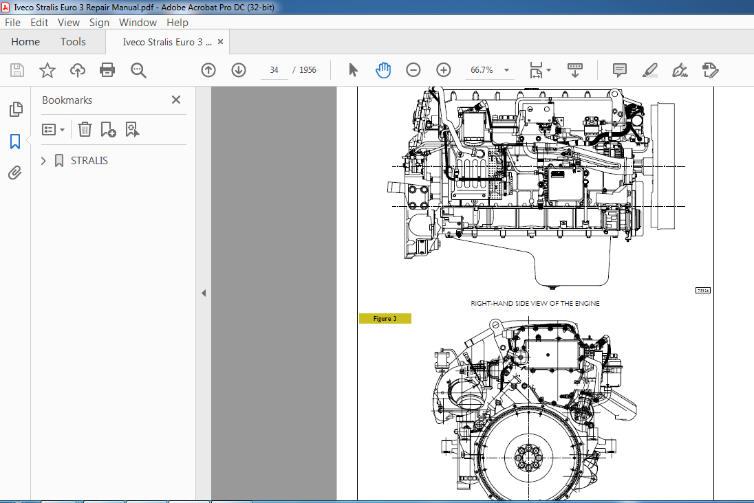
VIEWS OF THE ENGINE 33
TECHNICAL DESIGNATION 37
CHARACTERISTIC CURVES 38
GENERAL CHARACTERISTICS 40
ASSEMBLY CLEARANCE DATA 43
TIGHTENING TORQUE 49
TOOLS 55
ENGINE REMOVAL – REFITTING 65
Removal 65
Refitting 66
Filling the cooling system 67
Bleeding air from the supply system 68
Checks and tests 68
ELECTRO-MAGNETIC JOINT REPLACEMENT 69
Removal 69
Refitting 70
DISMANTLING THE ENGINE ON THE BENCH 73
REPAIR OPERATIONS 80
CYLINDER BLOCK 80
Checks and measurements 80
Cylinder liners 81
Replacing cylinder liners 82
Crankshaft 83
Measuring the main journals and crankpins 84
Preliminary measurement of main and big end bearing shell selection data 85
Selecting the main and big end bearing shells 86
Replacing the timing gear and oil pump 92
Checking main journal assembly clearance 92
Checking crankshaft end float 93
Piston connecting rod assembly 94
Piston rings 96
Connecting rods 97
Bushings 98
Checking connecting rods 98
Fitting the big end bearing shells 99
Mounting the piston rings 99
Fitting the big end bearing shells 99
Fitting connecting rod – piston assemblies in the cylinder liners 100
Checking piston protrusion 100
Checking crankpin assembly clearance 101
CYLINDER HEAD 101
Removing valves 101
Checking the planarity of the head on the cylinder block 101
Valves 101
Removing deposits and checking the valves 101
Valve seats 102
Checking clearance between valve-stem and associated valve guide 103
Valve guides 103
Replacing injector cases 103
Checking injector protrusion 105
TIMING GEAR 107
Camshaft drive 107
Idler gear pin 107
Idler gear 107
Twin intermediate gear pin 107
Twin idler gear 107
Replacing the bushings 107
Timing system 108
Checking cam lift and pin alignment 108
Bushings 109
Valve springs 111
Fitting valves and oil seal 112
ROCKER SHAFT 112
Rocker arms 113
Shaft 113
ENGINE ASSEMBLY ON BENCH 114
Fitting connecting rod – piston assemblies in cylinder liners 117
ENGINE FLYWHEEL 120
Fitting engine flywheel 120
Fitting camshaft 121
Fitting pump-injectors 122
Fitting rocker-arm shaft assembly 122
Camshaft timing 123
Phonic wheel timing 125
Intake and exhaust rocker play adjustment and pre-loading of rockers controlling pump injectors 126
Completing Engine Assembly 127
LUBRICATION 129
Oil pump 131
Overpressure valve 131
Oil pressure control valve 132
Heat exchanger 132
By-pass valve 134
Thermostatic valve 134
Engine oil filters 134
COOLING 135
Water pump 137
Thermostat 137
Electromagnetic coupling 137
TURBOCHARGING 138
Turbocharger HOLSET HY55V 138
REPAIRING ACTIONS 142
Actuator 142
Solenoid valve for VGT control 142
FEEDING 144
Fuel pump 145
Injector-pump 145
Replacing injectors-pump 145
Injector Phases 146
F3B Engine 151
VIEWS OF THE ENGINE 153
TECHNICAL DESCRIPTION 156
CHARACTERISTIC CURVES 157
GENERAL SPECIFICATIONS 160
ASSEMBLY DATA – CLEARANCE 163
TIGHTENING TORQUES 169
DIAGRAMS OF TIGHTENING SEQUENCE OF MAIN ENGINE COMPONENTS 172
TOOLS 176
ENGINE REMOVAL-REFITTING 187
Removal 187
Refitting 190
Filling the cooling system 191
Bleeding air from the system 191
Checks and tests 192
ELECTRO-MAGNETIC JOINT REPLACEMENT 193
Removal 193
Refitting 194
STRIPPING THE ENGINE ON THE BENCH 197
REPAIRS 204
CYLINDER BLOCK 204
Checks and measurements 204
Cylinder liners 205
Replacing the cylinder liners 206
Crankshaft 207
Measuring the main journals and crankpins 208
Preliminary measurement of data to select main bearing and big end bearing shells 209
Selecting the main bearing and big end bearing shells 210
Replacing the timing gear and oil pump 216
Checking main journal assembly clearance 216
Checking crankshaft end float 217
Connecting rod piston assembly 218
Piston rings 220
Connecting rod 221
Bushings 222
Checking connecting rods 222
Mounting the connecting rod — piston assembly 223
Mounting the piston rings 223
Fitting the big end bearing shells 223
Fitting connecting rod – piston assemblies in the cylinder liners 224
Checking piston protrusion 224
Checking crankpin assembly clearance 225
CYLINDER HEAD 225
Checking head bearing surface on cylinder block 225
Valves 225
Valve seats 226
Checking clearance between valve-stem and associated valve guide 227
Valve guides 227
Replacing injector cases 227
Checking injector protrusion 229
TIMING GEAR 231
Camshaft drive 231
Idler gear pin 231
Idler gear 231
Twin intermediate gear pin 231
Twin idler gear 231
Replacing the bushings 231
Timing system 232
Checking cam lift and pin alignment 232
Bushings 233
Valve springs 235
ROCKER SHAFT 236
Shaft 237
Rocker arms 237
ENGINE ASSEMBLY ON BENCH 238
Fitting connecting rod – piston assemblies in cylinder liners 241
Fitting the cylinder head 242
Fitting flywheel box 243
ENGINE FLYWHEEL 244
Fitting engine flywheel 244
Fitting camshaft 245
Fitting pump-injectors 246
Fitting rocker-arm shaft assembly 246
Camshaft timing 247
Phonic wheel timing 249
Adjusting rocker armclearance, intake, exhaust and pre-load of pump injector governing rocker arms 250
Completing assembly 251
LUBRICATION 253
Oil pump 255
Overpressure valve 255
Oil pressure control valve 256
Heat exchanger 256
By-pass valve 258
Thermostatic valve 258
Engine oil filters 258
COOLING 259
Water pump 261
Thermostat 261
Electromagnetic coupling 261
TURBOCHARGING 262
Turbocharger HOLSET HY 55 V 262
REPAIRING ACTIONS 266
Actuator 266
Solenoid valve for VGT control 266
FEEDING 268
Fuel pump 269
Injector-pump 269
Replacing injectors-pump 269
Injector Phases 270
Hydrocar pressure take-off on timing system 275
HYDROCAR PRESSURE TAKE-OFF ON TIMING SYSTEM – P T O (OPTIONAL) 277
Description 277
SPECIFICATIONS AND DATA 278
TIGHTENING TORQUES 279
ENGAGING POWER TAKE-OFF 280
REMOVING-REFITTING POWER TAKE-OFF 280
Fault Diagnosis 283
FAULT DIAGNOSIS 285
Diagnosis Instruments 285
Cluster Diagnosis 287
Troubleshooting via DTC-FMI codes 289
SECTION 3 – Clutch 317
Clutch 317
DESCRIPTION 319
Clutch 319
SPECIFICATIONS AND DATA 319
FAULT DIAGNOSIS 320
TIGHTENING TORQUES 323
TOOLS 323
REMOVING AND REFITTING THE CLUTCH 324
Removal 324
CHECKS 324
Refitting 325
REMOVING-REFITTING THE THRUST BEARING 325
REMOVING-REFITTING THE PEDAL UNIT 326
Removal (vehicles with EuroTronic Automated gearbox) 326
Removal (vehicles with ZF 16 S gearbox) 327
Refitting 328
PEDAL 328
UNIT REMOVAL-ASSEMBLY 328
CHECKING AND ADJUSTING STOPS ON CLUTCH PEDAL (vehicles with ZF 16 S gearboxes) 329
Clutch stop 329
Idle travel of clutch pedal 329
Pedal control valve stroke 329
HYDRAULIC CONTROL (vehicles with ZF 16 S gearboxes) 330
CLUTCH ACTUATOR FOR ZF 16 S GEARBOXES 331
Fitting and adjusting the clutch wear indicator 331
OPERATOR CYLINDER PUSH ROD ADJUSTMENT (new clutch) 332
CLUTCH ACTUATOR FOR EUROTRONIC AUTOMATED GEARBOX 333
Clutch actuator push rod adjustment (new clutch) 333
Fitting the clutch actuator 333
Replacing the clutch actuator 333
SECTION 4 – Gearbox 335
Gearbox 335
Gearboxes: ZF 16 S 181 D D – ZF 16 S 181 O D – ZF 16 S 221 D D 339
LOCATION OF GEARBOX DESCRIPTION PLATE 341
DESCRIPTION 342
OPERATION 344
Slow range 344
Fast range 345
EPICYCLIC REDUCTION GEAR CONTROL 346
Reduced speeds 346
Normal speeds 347
SPECIFICATIONS AND DATA 348
TIGHTENING TORQUES 352
TOOLS 353
GEARBOX FAULT DIAGNOSIS 358
REMOVING-REFITTING THE GEARBOX 361
Removal 361
Refitting 362
OVERHAULING THE GEARBOX 363
Servoshift gear box 363
Removal 363
Refitting 363
Disassembly 363
Assembly 365
Removing the rear box 369
Removing the epicyclic reduction gear unit (ERG) 369
Fitting the epicyclic reduction gear unit (ERG) 371
Refitting the epicyclic reduction gear unit ERG) rear box 374
Removing the gearbox 374
Removing the main shaft 377
Removing the drive input shaft 380
Removing the transmission shaft 381
CHECKS 381
Gearbox 381
Hubs – sliding sleeves – forks 381
Bearings 381
Shafts – gears 381
Synchronizing devices 381
BK-type single-cone synchronizing devices 381
Fitting the transmission shaft 382
Fitting the drive input shaft 382
Fitting the main shaft 383
Adjusting the main shaft 385
Fitting the gearbox 386
Oil pump 387
Adjusting the transmission shaft bearing end float 387
Drive input shaft cover 388
PNEUMATIC CONTROL OF GEARBOX 390
CONNECTING DIAGRAM FOR GEARBOXWITH SERVOSHIFT 391
ZF gearboxes with INTARDER hydraulic retarder, types: 16 S 181 D D /O D – 16 S 221 D D 395
SPECIFICATIONS AND DATA 397
TOOLS 398
Removing the hydraulic retarder from the gearbox on the stand 405
Refitting the hydraulic retarder 405
Removing the epicyclic reduction gear unit (ERG) rear box 406
Removing the epicyclic reduction gear unit (ERG) 406
Component parts of the epicyclic reduction gear unit 409
Fitting the epicyclic reduction gear unit (ERG) 410
Refitting the epicyclic reduction gear unit (ERG) rear box 412
Gearboxes: EuroTronic Automated 12 AS 2301 D D /O D EuroTronic Automated 16 AS 2601 D D /O D 415
DESCRIPTION 417
SPECIFICATIONS AND DATA 418
FAULT DIAGNOSIS 422
Diagnosis Instruments 422
Cluster Diagnosis 424
Troubleshooting via DTC-FMI codes 426
TIGHTENING TORQUES 460
TOOLS 463
OVERHAULING THE GEARBOX 469
Checks 469
Gearbox actuator 469
Removal 469
Refitting 470
Removing the rear box 470
Removing the rear box 471
Removing the epicyclic reduction gear train (E R G ) 472
Fitting the epicyclic reduction gear train (E R G ) 474
Adjusting epicyclic reduction gear train bearing end float 475
Adjusting main shaft end float 476
Synchronizing device assembly for engaging normal or reduced gears 478
Removal 478
Fitting 478
Removing the middle box 481
Removing the main shaft 483
Removing the drive input shaft 485
Removing the splitter synchronizing device 486
Fitting the splitter synchronizing device 487
Fitting the main shaft 488
Fitting the drive input shaft 488
Splitter control fork 491
Disassembly – Assembly 491
Gear control forks 491
Removal 491
Fitting 492
Transmission shafts 493
Disassembly – Assembly 493
Fitting the middle box 493
Fitting the front box 496
Front cover 498
Removal 498
Fitting the front cover 498
Adjusting drive input shaft bearing end float 498
Adjusting transmission shaft bearing end float 499
Clutch release lever 501
Gearboxes: EuroTronic Automated 12 AS 2301 D D /O D with Intarder EuroTronic Automated 16 AS 2601 D D /O D with Intarder 505
EuroTronic Automated 12 AS 2301 D D /O D — 16 AS 2601 D D /O D with intarder 507
SPECIFICATIONS AND DATA 507
EXPERIMENTAL TOOLS 508
REMOVING-REFITTING GEARBOX 509
Removal 509
Refitting 509
OVERHAULING THE GEARBOX 511
Removing the hydraulic retarder 511
Refitting the hydraulic retarder 512
Adjusting epicyclic reduction gear train bearing end float 512
Adjusting stator end float 513
Removing the rear box 514
Disassembling the E R G 515
Fitting the E R G 516
Power take-offs 521
POWER TAKE-OFFS ZF-TYPE 523
CHARACTERISTICS AND DATA 523
POWER TAKE-OFFS HIDROCAR TYPE 529
CHARACTERISTICS AND DATA 529
Transmission external control (except for vehicles equipped with Eurotronic gearshift) 535
TRANSMISSION EXTERNAL CONTROL 537
Transmission tie rod adjustment 537
SIDE TIE ROD 538
Removal 538
Refitting 539
TELESCOPIC TIE ROD 539
Removal 539
Refitting 539
TRANSMISSION IDLER ARM 539
Removal 539
Disassembly 540
Assembly 540
Refitting 540
CROSS TIE ROD 540
Removal 540
Refitting 540
SECTION 5 – Intarder – ZF hydraulic retarder 541
Intarder – ZF hydraulic retarder 541
LOCATION OF INTARDER HYDRAULIC RETARDER DESCRIPTION PLATE 543
GENERAL INFORMATION 544
OPERATION 544
Retarder engaged 545
Retarder disengaged 546
LAYOUT OF MAIN SYSTEM COMPONENTS ON THE RETARDER 547
REMOVING AND REFITTING THE RETARDER ON THE ZF S 181/221-OD GEARBOX 548
Removal 548
Refitting 549
Filling with oil 549
SPECIFICATIONS AND DATA 550
TIGHTENING TORQUES 551
TOOLS 552
FAULT DIAGNOSIS 554
OVERHAULING THE INTARDER HYDRAULIC RETARDER 558
Hydraulic accumulator 558
Removal 558
Fitting 558
Removing hydraulic retarder 558
Checking the component parts of the hydraulic retarder 563
Fitting the hydraulic retarder 564
Stator end float adjustment 569
SECTION 6 – Propeller shafts 571
Propeller shafts 571
CHARACTERISTICS AND DATA 573
STRALIS ( Tractors) CHARACTERISTICS AND DATA ( vehicles 4×2/6x2C/6×4) 575
STRALIS ( Cabs) CHARACTERISTICS AND DATA ( vehicles 4×2/6x2P/6×4) 576
DIAGNOSTIC 577
TIGHTENING TORQUES 579
TOOLS 579
REMOVING AND REASSEMBLING THE PROPELLER SHAFT 580
Removal 580
Reassembly 580
CHECKING THE PROPELLER SHAFT ON THE VEHICLE 581
REMOVING AND FITTING BACK THE UNIVERSAL JOINTS 582
REMOVING AND REASSEMBLING THE SUPPORT 582
SECTION 7 – Rear axles 583
Rear axles 583
FAULT DIAGNOSIS 585
REMOVING-REFITTING THE REAR AXLE 587
Removal 587
Refitting 587
REMOVING-REFITTING THE DIFFERENTIAL FROM THE REAR AXLE ON THE VEHICLE 588
Removal 588
Refitting 588
Rear Axle ARVINMERITOR U 177 E with disc brakes 591
LOCATION OF DIFFERENTIAL UNIT PLATES – REAR AXLE 593
DESCRIPTION 595
CHARACTERISTICS AND DATA 596
TIGHTENING TORQUES 597
TOOLS 599
OVERHAULING THE REAR AXLE ASSEMBLY 605
OVERHAULING THE WHEEL HUBS 605
Removal 605
Replacing wheel hub bearings 607
Checking the parts forming the wheel hubs 607
Replacing the wheel fixing pins 607
REMOVING AND REFITTING THE DIFFERENTIAL (with axle on stand 99322215) 611
Removal 611
Checking axle housing 611
Refitting 611
REPAIRING THE DIFFERENTIAL 612
Removing the differential 612
Removing the gearcase 613
REMOVING THE BEVEL PINION FROM THE SUPPORT 615
Differential component check 615
Fitting the gear housing 616
FITTING THE MOUNT ON THE BEVEL PINION 617
Reassembling the differential housing 619
ADJUSTING THE CAP GAP 621
CORRECTING THE CROWNWHEEL AND PINION CONTACTS (AFTER ASSEMBLY) 624
WORK ON THE VEHICLE 627
REPLACING THE BEVEL PINION MOUNT SEAL 627
Disassembly 627
Assembly 628
Rear axle ARVINMERITOR U 177 E whit drum brakes 631
LOCATION OF DIFFERENTIAL UNIT PLATES – REAR AXLE 633
DESCRIPTION 635
CHARACTERISTICS AND DATA 636
TIGHTENING TORQUES 639
TOOLS 641
OVERHAULING THE REAR AXLE ASSEMBLY 647
OVERHAULING THE WHEEL HUBS 647
Removal 647
Wheel hub component check 648
REPLACING THEWHEEL HUB BOLTS 649
Wheel hub reassembly 649
REMOVING AND REASSEMBLING THE DIFFERENTIAL 651
Removal 651
Axle casing check 651
Rear Axle ARVINMERITOR MS 13-175 (R 1783) with disc brakes 655
LOCATION OF DIFFERENTIAL UNIT PLATES – REAR AXLE 657
DESCRIPTION 659
CHARACTERISTICS AND DATA 659
Rear axle ARVINMERITOR MS 13-175 (R 1783) whit drum brakes 663
LOCATION OF DIFFERENTIAL UNIT PLATES – REAR AXLE 665
DESCRIPTION 667
CHARACTERISTICS AND DATA 667
Axles in Tandem 671
Axles in Tandem (Intermediate) ARVINMERITOR RP 160 E (R 2478) 673
LOCATION OF DIFFERENTIAL UNIT PLATES – REAR AXLE 675
DESCRIPTION 676
SPECIFICATIONS AND DATA 677
TIGHTENING TORQUES 679
TOOLS 683
EXPERIMENTAL TOOLS 690
SERVICING INTERMEDIATE AXLE ASSEMBLY RP 160 E (R2478) 693
AIR BREATHER REMOVAL-REFITTING 693
SERVICINGWHEEL HUBS 693
Checking wheel hub components 694
ASSEMBLING WHEEL HUBS 695
REMOVING DIFFERENTIAL GEAR — TRANSFER BOX (with rear axle on stand 99322215) 698
REFITTING DIFFERENTIAL GEAR — TRANSFER BOX (with rear axle on stand 99322215) 698
REPAIRING INTER-AXLE UNIT 699
Dismantling inter-axle unit 699
Checking inter-axle unit components 701
Fitting inter-axle unit 701
Adjusting drive input shaft bearing end float 703
Adjusting differential lock and inter-axle control pin end-stop 703
REPAIRING MAIN DIFFERENTIAL – DISMANTLING DIFFERENTIAL CASING 704
Dismantling gear cage 707
Checking differential components 707
Assembling gear cage 708
ASSEMBLING DIFFERENTIAL CASING 709
Calculating bevel pinion positionin differential casing 709
COMPUTATIONAL EXAMPLES 710
Determining the thickness of the bevel pinion bearing clearance adjustment rings 710
Adjusting the cap gap 713
CORRECTING THE CROWNWHEEL AND PINION CONTACTS (AFTER ASSEMBLY) 715
REMOVING-SERVICING-REFITTING INTER-AXLE OUTPUT SHAFT 718
Axles in Tandem (Rear) ARVINMERITOR RR 160 E (R 0878) 721
LOCATION OF DIFFERENTIAL UNIT PLATES – REAR AXLE 723
DESCRIPTION 724
SPECIFICATIONS AND DATA 725
TIGHTENING TORQUE 727
TOOLS 729
SERVICING REAR AXLE ASSEMBLY RR 160 E (R 0878) 734
AIR BREATHER REMOVAL/ INSTALLATION 734
SERVICING WHEEL HUBS 734
REMOVING DIFFERENTIAL (with axle on stand 99322215) 734
REFITTING DIFFERENTIAL (with axle on stand 99322215) 734
REPAIRING DIFFERENTIAL 735
Removing differential lock 735
Dismantling differential casing 736
Dismantling gear cage 737
Dismantling bevel pinion support 737
Checking differential components 741
Assembling gear cage 741
Assembling differential casing 743
ADJUSTING THE CAP GAP 745
CORRECTING THE CROWNWHEEL AND PINION CONTACTS (AFTER ASSEMBLY) 748
Axles in Tandem (Rear) ARVINMERITOR RR 167 E (R 0878) 751
LOCATION OF DIFFERENTIAL UNIT PLATES – REAR AXLE 753
DESCRIPTION 755
CHARACTERISTICS AND DATA 755
TIGHTENING TORQUES 757
TOOLS 759
OVERHAULING REAR AXLE ASSEMBLY RR 167 E (R 0878) 765
Rear axle 451391 HR (R 8284) 769
DESCRIPTION 771
SPECIFICATIONS AND DATA 772
TIGHTENING TORQUES 773
TOOLS 775
REAR AXLES ASSEMBLY OVERHAUL 781
Disassembly 781
Epicycloid reduction gear disassembly 781
Wheel hub disassembly 782
CHECKING THE WHEEL HUB AND EPICYCLOID REDUCTION GEAR UNIT PARTS 784
WHEEL HUB ASSEMBLY 785
Assembling the epicycloid reduction gear 787
REMOVING-REFITTING THE DIFFERENTIAL 790
REPAIRING THE DIFFERENTIAL 792
Disassembly 792
Gear housing disassembly 793
Removing the bevel pinion from the support 794
CHECKING THE DIFFERENTIAL COMPONENTS 796
Gear housing assembly 797
Assembling the bevel pinion support 798
Procedure to follow to determine the thickness of the bevel pinion rolling torque adjusting ring 798
Differential housing assembly 800
Gear housing bearings rolling torque adjustment 801
SECTION 8 – Axles 805
Axles 805
Front axle 5876/4 (F 8021) 5876/5 (F 8021) Steering central added axle 5876/2 (F 8021) 809
DESCRIPTION 811
SPECIFICATIONS AND DATA 812
FAULT DIAGNOSIS 814
TIGHTENING TORQUES 817
TOOLS 819
REMOVING AND REFITTING FRONT AXLE 823
Vehicles with mechanical front suspension 823
Removal 823
Refitting 823
REMOVING AND REFITTING FRONT AXLE 824
Vehicles with pneumatic front suspension and longitudinal bars 824
Removal 824
Refitting 825
VEHICLE CHECKS 826
Tie rods 826
Swivel heads 826
CHECKING SWIVEL HEAD PLAY 826
FRONT AXLE ASSEMBLY OVERHAUL 827
REMOVING – REFITTINGWHEEL HUBS 827
Removal 827
Replacing wheel hub bearings 828
Replacing wheel fixing pins 829
Refitting wheel hubs 829
Checking wheel hub bearing end float 829
Measuring rolling torque 830
REMOVING AND REFITTING TRANSVERSE TIE ROD 830
REPLACING TRANSVERSE TIE ROD SWIVEL HEADS 831
REMOVING AND REFITTING LEVERS FOR LONGITUDINAL TIE ROD 831
REMOVING – REFITTING LEVER FOR TRANSVERSE TIE ROD 831
REMOVING AND REFITTING PIN FOR STUB AXLE 831
Removal 831
Replacing kingpin bearing 832
Checking and adjusting clearance between stub axle and axle 833
CHECKING AND MEASURING THE AXLE BODY 834
Checking levelness of leaf spring supporting surfaces with respect to the holes for the kingpins 834
Checking angle of holes for kingpins 835
Axle 5876 (F 8021) 839
DESCRIPTION 841
SPECIFICATIONS AND DATA 842
TIGHTENING TORQUE 843
TOOLS 844
FRONT AXLE ASSEMBLY OVERHAUL 848
REMOVING – REFITTINGWHEEL HUBS 848
Removal 848
Refitting wheel hubs 849
Rigid rear added axle 55080/DI (N 8071) 853
DESCRIPTION 855
CHARACTERISTICS AND DATA 856
TIGHTENING TORQUE 857
TOOLS 858
REMOVING-REFITTING 860
Removal 860
Refitting 861
REPAIRS 861
Rigid rear added axle 55080/TI (N 8071) 865
DESCRIPTION 867
CHARACTERISTICS AND DATA 868
TIGHTENING TORQUES 869
TOOLS 870
REPAIRS 871
Rigid rear added axle 56082/D1 (N 9171) 875
DESCRIPTION 877
CHARACTERISTICS AND DATA 878
TIGHTENING TORQUE 879
TOOLS 880
Rigid rear added axle 56082/T1 (N 9171) 885
DESCRIPTION 887
CHARACTERISTICS AND DATA 888
TIGHTENING TORQUE 889
TOOLS 890
REMOVING-REFITTING 892
REPAIR OPERATIONS 892
Steering rear added axle 57080/DI (N 8072) 895
DESCRIPTION 897
CHARACTERISTICS AND DATA 898
TIGHTENING TORQUES 900
TOOLS 901
REPAIRS 905
PNEUMATIC LIFT 905
GENERAL 905
LOCATION ON THE VEHICLE OF THE MAIN COMPONENTS OF THE HYDRAULIC SYSTEM 906
HYDRAULIC SYSTEM 907
HYDRAULIC SYSTEMWORKING DIAGRAM 908
VEHICLESWITH PNEUMATIC REAR SUSPENSIONS AND PNEUMATIC LIFTING 909
Location on the vehicle of the main components 909
Pneumatic working diagram, rear air suspensions and air lift for added axles with single wheels 910
FAULT DIAGNOSIS 911
TIGHTENING TORQUES (Steering and lifting device linkage) 914
CHARACTERISTICS AND DATA 915
Steering and third axle hydraulic system 915
MAIN HYDRAULIC SYSTEM COMPONENTS 916
HYDRAULIC ACCUMULATOR 916
Nitrogen pressure checking and recharging 916
OPERATOR CYLINDER 916
Disassembly 917
Assembly 917
Checking cylinder oil sealing on the vehicle 917
CENTRING CYLINDER 917
Disassembly 918
Assembly 918
Checking cylinder oil sealing on the vehicle 918
ADDITIONAL AXLE PNEUMATIC LIFTING DEVICE REMOVAL AND REFITTING 919
Removal 919
Refitting 919
AIR BLEEDING FROM THE HYDRAULIC CIRCUIT 920
Filling up and bleeding the power steering hydraulic circuit (circuit 1) 921
Filling up and bleeding the power steering hydraulic circuit (circuit 2) 921
Steering rear added axle 57080/TI (N 8072) 925
DESCRIPTION 927
CHARACTERISTICS AND DATA 928
TIGHTENING TORQUES 930
TOOLS 931
REPAIR OPERATIONS 934
Wheel geometry 937
GENERAL INFORMATION 939
Steering wheel angles 939
FRONTWHEEL GEOMETRY (4X2 vehicles) 940
Positioning clips and headlights 940
Electronic compensation of rim eccentricity 941
Wheel alignment 941
Checking wheel toe-in 942
Checking wheel deviation 942
Checking camber 942
Checking kingpin angle and caster 943
Checking rear axle alignment 944
VEHICLE WHEEL GEOMETRY WITH CENTRAL ADDED AXLE (6X2 C) 944
Checking steering angles 946
Vehicle wheel geometry with steering rear added axle and pneumatic lifting 946
SECTION 9 – Suspensions 949
Suspensions 949
SUSPENSIONS 951
DESCRIPTION 951
Mechanical front suspension 951
Pneumatic front suspension 951
Pneumatic rear suspension 951
SPECIFICATIONS AND DATA 952
Leaf spring for central added axle (vehicles with air suspension) 957
MECHANICAL FRONT SUSPENSION ASSEMBLY DRAWING 958
Front shock absorbers 961
Rear shock absorbers 962
AIR SUSPENSION 963
Chassis frame lifting, lowering and self-levelling with remote control 963
Saving Levels 963
Working diagram of pneumatic rear suspensions for 4x2T/P tractors 964
Working diagram of suspensions for 4x2T/FP/FP-CT/FP-GV tractors 965
Working diagram of air suspensions for 4x2FP vehicles 966
Working diagram of air suspensions for 6x2Y/FP/FS-GV vehicles 967
Working diagram of air suspensions for 6x2Y/FP/FS-CM vehicles 968
Working diagram of air suspensions for 6x2Y/FP/FS-GV vehicles 969
Working diagram of air suspensions for 6x2Y/FP/FS-CM vehicles 970
Working diagram of rear air suspensions for 6x2Y/PT vehicles 971
Working diagram of rear air suspensions for 6x2Y/PS vehicles 972
Working diagram of rear air suspensions for 6x2Y/PS vehicles 973
Working diagram of air suspensions for 6x2TX/P vehicles 974
Working diagram of rear air suspensions for 6x2Y/FT vehicles 975
Working diagram of rear air suspensions for 6x2Y/FT vehicles 976
Working diagram of pneumatic rear suspensions for 6×4 Z/P – HM – 6×4 TZ/P – HM vehicles 977
Rear air suspension main diagram for 4X2 P vehicles 978
CHARACTERISTICS AND DATA 979
Pneumatic System 979
MAIN COMPONENTS OF THE PNEUMATIC SYSTEM 980
Fault Diagnosis 980
Controlled pressure valve 980
Level sensor 980
Electro-Pneumatic Control Valve 981
Load detector pressure sensor 982
Low air pressure switch 982
Air spring 982
ECAS Control Unit 982
FAULT DIAGNOSIS 983
Diagnosis Instruments 983
Cluster Diagnosis 985
Troubleshooting via DTC-FMI codes 987
TOOLS 1012
TIGHTENING TORQUES 1014
Mechanical front suspension 1014
Pneumatic front suspension 1015
Pneumatic front suspension with bars 1016
Central added axle pneumatic suspensions 6×2 C vehicles 1017
Pneumatic rear suspension 4×2 — 6×2 C vehicles 1018
Pneumatic rear suspension 6×2 P/PT/FT vehicles 1019
Pneumatic rear suspension 6×2 P/FP/FS vehicles 1020
Pneumatic rear suspension 6×2 P vehicles 1021
Pneumatic rear suspension 6×2 P/PS vehicles 1022
Pneumatic rear suspension 6×4 P vehicles 1023
REMOVAL-REFITTING OF FRONT LEAF SPRING 1024
Removal 1024
Refitting 1024
REMOVING-REFITTING FRONT SUSPENSION BARS 1025
Removing longitudinal bars 1025
Removing transverse bar 1025
Refitting 1025
REAR SUSPENSIONS 1027
Removal 1027
Refitting 1027
REMOVING-REFITTING THE REAR AXLE LONGITUDINAL SUSPENSION ARM 1028
REMOVING-REFITTING THE REAR ADDED AXLE LONGITUDINAL SUSPENSION ARM 1028
REMOVING-REFITTING THE REAR AXLE TRIANGULAR SUSPENSION ARM 1028
REMOVING-REFITTING THE REAR ADDED AXLE TRIANGULAR SUSPENSION ARM 1028
Removal 1028
Refitting 1028
REPLACING THE SUSPENSION ARM FLEXIBLE PIN 1029
Removal 1029
Refitting 1029
STABILIZER BAR 1030
FRONT STABILIZER BAR 1030
CENTRAL ADDED AXLE STABILIZER BAR (6×2 C vehicles) 1030
REAR STABILIZER BAR 1030
REAR ADDED AXLE STABILIZER BAR (6x2P vehicles) 1030
Removal 1030
Refitting 1030
RUBBER BUSHINGS 1033
Replacing front stabilizer bar rubber bushings 1033
Replacing rear stabilizer bar rubber bushings 1033
SHOCK ABSORBERS 1034
Removal-refitting 1034
Front axle shock absorbers (6×2 C vehicles) 1034
Central added axle shock absorbers 1034
Rear axle shock absorbers 1034
Rear added axle shock absorbers (6×2 P vehicles) 1034
Removal 1034
Refitting 1034
CHASSIS FRAME ADJUSTMENT 1035
SECTION 10 – Wheels and tyres 1041
Wheels and tyres 1041
DESCRIPTION 1043
CHARACTERISTICS AND DATA 1043
Tyre inflation pressures 1043
TOOLS 1044
FAULT DIAGNOSIS 1044
STATIC BALANCING OF THE WHEELS 1047
CORRECTING RESIDUAL STATIC IMBALANCE 1048
TYRE PRESSURE 1048
HOW TYRE BEHAVIOUR DEPENDS ON PRESSURE 1049
SECTION 11 – Steering 1051
Steering 1051
DESCRIPTION 1053
Vehicle steering control diagram 1054
Vehicle steering control diagram with front air suspension and longitudinal bars 1055
Vehicle steering control diagram with front air suspension and leaf springs 1056
6×2 Vehicle steering control diagram with front mechanical suspension 1057
6x2c (right-hand drive) Vehicle steering control diagram with front air suspension and leaf springs 1058
6x2p (steering rear axle) Vehicle steering control diagram with front mechanical 1059
6x2p (steering rear axle) Vehicle steering control diagram with front air suspension and leaf springs 1060
6x2p (steering rear axle) Vehicle steering control diagram with front air suspension and longitudinal bars 1061
SPECIFICATIONS AND DATA 1062
FAULT DIAGNOSIS 1063
TIGHTENING TORQUES 1068
TOOLS 1069
REMOVING-REFITTING THE POWER STEERING SYSTEM 1071
Removal 1071
Refitting 1073
Removing-Fitting the Steering Lever 1073
STEERING CONTROL 1074
REMOVING-REFITTING THE STEERING CONTROL ASSEMBLY 1075
Removal 1075
Refitting 1077
Changing the pneumatic cylinder 1077
Removal 1077
Refitting 1078
BLEEDING THE POWER STEERING SYSTEM 1080
MEASURING STEERING BOX PLAY AT THE STEERINGWHEEL 1080
CHECKING THE MAXIMUM PRESSURE OF THE POWER STEERING SYSTEM 1080
Setting the automatic hydraulic steering limit 1080
SECTION 12 – Air system – Brakes 1081
Air system – Brakes 1081
SYMBOLS FOR AIR/HYDRAULIC SYSTEM CIRCUIT DIAGRAMS (TANKS AND ACCUMULATORS) 1085
SYMBOLS FOR AIR/HYDRAULIC SYSTEM CIRCUIT DIAGRAMS (VALVES) 1086
SYMBOLS FOR AIR-HYDRAULIC SYSTEM DIAGRAMS (TANKS AND ACCUMULATORS) 1092
Print 603 43 671 SYMBOLS FOR AIR/HYDRAULIC SYSTEM CIRCUIT DIAGRAMS (CONVERTERS, CYLINDERS AND CALLIPERS) 1093
SYMBOLS FOR AIR/HYDRAULIC SYSTEM CIRCUIT DIAGRAMS (CALLIPERS AND CYLINDERS) 1094
SYMBOLS FOR AIR/HYDRAULIC SYSTEM CIRCUIT DIAGRAMS (SEMI-COUPLINGS AND COUPLING CONNECTORS) 1095
SYMBOLS FOR AIR/HYDRAULIC SYSTEM CIRCUIT DIAGRAMS (SEMI-COUPLINGS AND COUPLING CONNECTORS) 1096
SYMBOLS FOR AIR/HYDRAULIC SYSTEM CIRCUIT DIAGRAMS (INDICATORS AND SWITCHES) 1097
SYMBOLS FOR AIR/HYDRAULIC SYSTEM CIRCUIT DIAGRAMS (BRAKES) 1098
PIPINGS AND FITTINGS 1099
In general 1099
Rigid pipings reflanging 1099
Rigid pipings bending 1100
Rigid pipings cutting 1100
Flexible pipings replacementwith traditional fittings 1101
Flexible pipings replacement with quick connection fittings 1102
EBS (ELECTRONIC BRAKE SYSTEM) 1104
EBS Benefits 1104
Tractor and trailer compatibility at any time 1104
Complete fault-diagnosis structures 1104
OPERATING LOGIC 1105
BRAKE SYSTEM 1106
AUXILIARY BRAKE INTEGRATION 1107
“ABS-EBL” SYSTEM (ANTI-LOCK BRAKE SYSTEM — ELECTRONIC BRAKE LIMITER) 1108
“ABS” (Anti-Lock Brake System) 1108
EBL (Electronic Brakes Limiter) 1109
Operating Logic 1109
BRAKE SYSTEM WITH EBS DEVICE 1110
EBS working diagram for 4×2 vehicles (tractors) 1110
EBS working diagram for 6×2 vehicles (tractors) 1111
EBS working diagram for 4×2 vehicles (trucks) 1112
EBS working diagram for 6×2 vehicles (trucks) 1114
BRAKE SYSTEM WITH ABS-EBL DEVICE 1118
Working diagram for 4×2 vehicles 1118
Working diagram for 6×2 vehicles (trucks) 1120
Working diagram for 6×2 vehicles (tractors) 1122
ABS-EBL working diagram for 6×2 vehicles (tractors) 1123
Working diagram for 6×4 vehicles 1124
DESCRIPTION 1126
Service braking 1126
Emergency braking 1126
Parking brake 1126
Exhaust brake 1126
BRAKES 1126
Disc Brakes 1126
Drum Brakes 1126
FAULT DIAGNOSIS 1127
Diagnosis Instruments 1127
Cluster Diagnosis 1129
System ABS – Troubleshooting via DTC-FMI codes 1131
System EBS – Troubleshooting via DTC-FMI codes 1155
TIGHTENING TORQUES 1233
TOOLS 1236
SPECIFICATIONS AND DATA – PNEUMATIC SYSTEM 1244
SPECIFICATIONS AND DATA – BRAKES 1252
CHECKS ON MAIN COMPONENTS OF BRAKE SYSTEM 1254
MAIN COMPONENTS OF THE BRAKING SYSTEM 1256
Compressor 1256
Head locking screw tightness 1256
Fault diagnosis 1257
A P U (Air Processing Unit) 1257
Duplex control valve vehicles without EBS) 1258
Duplex control valve with electric transmitter (vehicles with EBS) 1258
Fault Diagnosis (vehicles without EBS) 1258
Relay valve (vehicles without EBS) 1259
Proportional relay valve for front axle (vehicles with EBS) 1259
Fault Diagnosis (vehicles without EBS) 1259
Coupling heads 1259
Rear axle electro-pneumatic modulator (for vehicles with EBS) 1260
Fault Diagnosis 1260
Redundancy valve (for 4×2 and 6×2 trucks) 1261
ABS-EBS solenoid valve 1261
Dual stop valve 1261
Triple servo control valve (vehicles without EBS) 1261
Predominance control 1262
Fault Diagnosis 1262
Trailer servo control valve (vehicles with EBS) 1263
Parking brake hand control valve (vehicles suited to towing) 1263
Pressure test point valve 1263
Manual control valve to slow down the trailer (optional extra) 1263
Fault Diagnosis (parking brake control valve) 1263
Controlled pressure valve 1264
Fault Diagnosis 1264
Check valve (vehicles suited to towing) 1264
Low-pressure switch 1264
Electro-pneumatic valve for ASR 1265
Speed sensor 1265
Electronic control unit 1265
Pressure sensor 1265
Diaphragm brake cylinder for front and added front axle disc brake) 1266
Diaphragm brake cylinder (for front and added front axle drum brake) 1266
Combined brake cylinder (for front and rear disc brake) 1266
Combined brake cylinder (for front and rear drum brake) 1266
Combined cylinder emergency brake release device 1267
Repairs 1267
Fault Diagnosis 1267
DISC BRAKES TYPE KNORR SB7 (vehicles without EBS) 1268
DISC BRAKES TYPE KNORR SB7 (vehicles with EBS) 1269
DISC BRAKES KNORR TYPE (CALIPER SN7) 1270
Brake caliper components 1271
Operation 1272
CHECKS 1272
Efficiency of automatic clearance recovery 1272
Brake lining thickness 1273
OVERHAULING FRONT DISC BRAKES 1274
Replacing brake linings 1274
Removing and refitting brake callipers 1277
Removal 1277
Refitting 1278
Removing and refitting wheel hubs 1278
Removal 1278
Refitting 1279
BRAKE CALIPER OVERHAUL 1280
Disassembly 1280
Component part cleaning and check 1281
Assembly 1281
OVERHAULING BRAKE CALLIPERS SB7 1284
Removal 1284
Cleaning and checking component parts 1284
Assembly 1285
OVERHAULING BRAKE DISCS 1286
TURNING AND GRINDING BRAKE DISCS 1286
OVERHAULING REAR DISC BRAKES 1287
Replacing brake linings 1287
OVERHAULING THE DRUM BRAKES 1290
Removing/fitting the front drum brakes 1290
Removing the rear drum brakes 1290
Turning drums 1293
Replacing brake linings 1293
Assembly 1294
SECTION 13 – Bodywork – Chassis frame 1297
Bodywork – Chassis frame 1297
CAB 1301
General information 1301
FEATURES AND DATA 1301
TOOLS 1301
TIGHTENING TORQUE 1302
REPAIRS REMOVING-REFITTING THE CAB 1305
Removal 1305
Removing the bumpers 1307
Refitting 1309
REPLACING THE FRONT SHOCK ABSORBER 1310
Removal 1310
Refitting 1310
REPLACING THE CAB SUSPENSION FRONT MOUNTING RUBBER-TYPE BUSHINGS 1310
Removal 1310
Refitting 1311
REPLACING THE CAB FRONT MOUNT BUSHINGS 1311
Removal 1311
Refitting 1311
REMOVING — REFITTING THE STABILIZER BAR 1311
Removal 1311
Refitting 1311
CHANGING THE REAR SHOCK ABSORBER 1313
Removal 1313
Refitting 1313
CHANGING THE CAB LOCK 1313
Removal 1313
Refitting 1313
CHANGING THE SWINGING BRACKET BUSHING 1313
Removal 1313
Refitting 1314
Adjusting the front levelling valve linkwork 1315
CAB TILTING 1317
CAB TILTING UNIT 1318
Removal 1318
Refitting 1318
Checking the oil level 1318
Periodic level check 1318
REPLACING THEWINDSHIELD 1319
Removal 1319
Refitting 1319
REPLACING THEWINDING WINDOW 1320
Removal 1320
Refitting 1321
REPLACING THEWINDOWWINDER 1321
Removal 1321
Refitting 1322
REPLACING THE DOOR LOCK 1322
Removal 1322
Refitting 1322
REPLACING THE OUTSIDE HANDLE OF THE DOOR 1323
Removal 1323
Refitting 1323
CHANGING THE INSIDE HANDLE 1323
Removal 1323
Refitting 1323
CHANGING THE SIDE MIRRORS 1324
Removal 1324
Refitting 1324
CHANGING THE DOOR 1324
Removal 1324
Refitting 1324
REPLACING THE FIXED WINDOW 1325
Removal 1325
Preparing the window bay 1325
Preparing the window 1325
Refitting 1325
REPLACEMENT OF SIDE LID OPENING CONTROL 1327
Removing 1327
Fitting 1328
Lid opening control adjustment 1328
DRIVER’S SEAT 1329
Removal 1329
Refitting 1329
Component layout 1330
REMOVING THE DRIVER’S SEAT 1331
Removing-fitting the cushion 1331
Removing-fitting the cushion slider 1331
Removing-fitting the seatbelt 1332
Removing-fitting seatbelt connection and right-hand side upholstery 1332
Removing — fitting the left-hand side upholstery, IPS valve and heating switch 1333
Removing – fitting the back 1333
Removing – fitting the back adjustment lever 1334
Removing – fitting the height adjustment device 1334
Removing – fitting the seat angle adjustment device 1334
Removing — fitting the flexible cable of the shock absorber adjustment device 1334
Removing — fitting the back adjustment lever segment 1335
Removing – fitting the air spring 1335
Removing – fitting the shock absorber 1335
Removing – fitting the height adjustment valve 1336
Removing – fitting the height locking system 1336
Removing — fitting the flexible cable of the horizontal lever suspension 1336
Removing – fitting the fast lowering magnetic valve 1337
Removing – fitting the fast lowering switch 1337
Removing – fitting the lumbar support device 1337
Removing – fitting the back upholstery 1338
Removing – fitting the cushion upholstery 1338
AIR INTAKE LID REMOVAL AND REFITTING 1339
Removal 1339
Refitting 1339
AIR INTAKE LID MOTOR REPLACEMENT 1339
Removing 1339
Refitting 1340
WINDSCREEN SUN VISOR REEL REMOVAL/REFITTING 1340
Removal 1340
Refitting 1341
WINDSCREEN SUN VISOR REEL MOTOR REPLACEMENT 1341
Removing 1341
Refitting 1341
CABIN REFRIGERATOR 1341
Preliminary checks 1341
Removal 1342
Refitting 1342
OVERHAULING 1342
Removing 1342
Fan disassembling 1342
Disassembling the anti-tipping probe with electronic circuit on the control unit 1343
Electronic control unit disassembling 1344
Checks 1344
Fitting 1344
INSTRUMENT PANEL 1345
CENTRAL INSTRUMENT PANEL 1345
FASCIA COVERING 1346
CAB AIR-CONDITIONING 1351
General 1351
VENTILATION 1351
Description 1351
AIR-CONDITIONING AND HEATING 1352
Description 1352
Air-conditioning 1352
Heating 1352
Air-conditioning controls assembly 1352
Automatic 1352
Manual 1352
Heating and ventilation 1352
COMPONENT LAYOUT (WEBASTO AIR CONDITIONER) 1353
HEATER ASSEMBLY COMPONENT LAYOUT (WEBASTO) 1354
MAIN COMPONENTS OF AIR CONDITIONER AND HEATER (WEBASTO) 1355
Outside temperature sensor 1356
Inside temperature sensor 1356
Three-way solenoid valve (WEBASTO) 1357
Compressor 1357
Dehumidifier filter and safety pressure switches 1358
Geared motors 1359
Evaporator temperature sensor 1360
Blown air temperature sensor 1360
Expansion valve 1361
PROCEDURE FOR EMPTYING AND REFILLING THE AIR-CONDITIONING SYSTEMS WITH R134A REFRIGERANT 1362
R134A refrigerant recovery and refilling station (99305146) 1362
SAFETY STANDARDS 1363
CONTROL FASCIA 1364
OPERATION FLOW CHART 1366
RECOVERING REFRIGERANT FROM THE VEHICLE SYSTEM 1367
CREATING A VACUUM IN THE SYSTEM 1369
RESTORING OIL IN THE SYSTEM 1371
FILLING THE SYSTEMWITH REFRIGERANT 1372
CHECKINGTHEPRESSURES INTHESYSTEM 1374
OPERATIONS PRIOR TO DISCONNECTING THE STATION FROM THE SYSTEM 1374
LEAK FINDER FOR AIR-CONDITIONING SYSTEMSWITH HFC R134A (9905147) 1374
REPAIR OPERATIONS 1375
HEATER 1375
Removal 1375
Refitting 1375
ADDITIONAL AIR HEATER SYSTEM 1376
Removal 1376
Refitting 1376
DEFROST CONTROL MOTOR 1376
Removal 1376
Refitting 1377
AIR RECIRCULATION DOOR CONTROL MOTOR 1378
Removal 1378
Refitting 1378
AIR MIXING DOOR CONTROL MOTOR 1378
Removal 1378
Refitting 1378
HEATER RADIATOR TEMPERATURE SENSOR 1379
Removal 1379
Refitting 1379
FLOOR AIR DOOR CONTROL MOTOR 1379
Removal 1379
Refitting 1379
ELECTRIC FAN 1380
Removal 1380
Refitting 1380
HEATER RADIATOR 1380
Removal 1380
Refitting 1381
POLLEN FILTER 1382
Removal 1382
Refitting 1382
AIR-CONDITIONER COMPRESSOR 1382
Removal 1382
Refitting 1382
AIR-CONDITIONER CONDENSER 1383
Removal 1383
Refitting 1383
OUTSIDE AIR TEMPERATURE SENSOR 1383
Removal 1383
Refitting 1383
DIAGNOSTICS INSTRUMENTS 1384
MODUS – IWT – IT 2000 1384
MODUS 1384
IWT 1384
IT 2000 1384
Troubleshooting the air-conditioner system 1385
Troubleshooting the additional air heater system 1389
SECTION 14 – Scheduled maintenance 1397
Scheduled maintenance 1397
MAINTENANCE 1399
Maintenance services chart 1399
CHECKS AND/OR MAINTENANCEWORK 1400
DIAGRAM OF POINTS FOR CHECKS AND/OR MAINTENANCEWORK 1401
CHECKS AND/OR MAINTENANCEWORK 1403
MAINTENANCEWORK 1404
M1 SERVICE 1404
M2 SERVICE 1408
EXTRA PLAN MAINTENANCE 1410
EP1 SERVICE 1410
EP2 SERVICE 1410
EP3 SERVICE 1410
T1 SERVICE 1411
T2 SERVICE 1411
T3 SERVICE 1412
T4 SERVICE 1413
SECTION 15 – Electric/electronic system 1415
Electric/electronic system 0
UPDATE DATA 1417
GENERAL LIST OF CONTENTS 1419
INTRODUCTION 1421
General warnings for electrical/electronic components 1423
Component Code 1425
Vehicle technical data 1430
GENERAL 1431
Description of the Multiplex system 1433
Power Network 1452
Mass points 1453
List of st junction connector on board the vehicle 1457
COMPONENTS 1497
Remote control/fuse holder center 1499
Supplementary remote switches 1501
Supplementary fuses 1504
Instrument panel 1506
Controls on central panel 1507
Controls on left panel frame 1508
Controls on right panel frame 1509
Light setting adjustment 1510
Controls on the steering wheel 1511
Heat rearview mirror adjustment 1512
Left light control 1513
External light rotating switch 1517
Emergency switch 1518
Tire selectors 1519
Diagnosis connector 1520
VDI electronic center 1521
Wall pass 1522
Alternator 1527
Starter motor 1529
ELECTRONIC SYSTEMS 1531
MULTIPLEX SYSTEM 1533
Cluster 1535
Body Computer 1544
Front Frame Computer (FFC) 1556
Rear Frame Computer (RFC) 1559
Passenger Door Module (PDM) 1564
Driver Door Module (DDM) 1565
Cabin Module (CB) 1566
Steering Wheel Interface (SWI) 1568
Spiraled contact 1571
Bed Module 1576
CONDITIONER 1577
HYDRONIC D 10 WATER HEATER 1592
IMMOBILIZER 1599
EDC 6 2 1603
EBS 1640
ABS — EBL 1658
ECAS 1684
EUROTRONIC AUTOMATED 1705
INTARDER 1725
DIAGNOSIS 1733
DIAGNOSTIC METHOD 1735
DIAGNOSTICS 1736
Example of anomaly 1737
DIAGNOSIS TOOLS 1739
MULTIPLEX SYSTEM ERROR CODES 1741
CIRCUIT CHARTS 1883
CHART 1 1885
CHART 2/1 1886
CHART 2/2 1887
CHART 2/3 1888
CHART 3/1 1889
CHART 3/2 1890
CHART 4/1 1891
CHART 4/2 1892
CHART 4/3 1893
CHART 4/4 1894
CHART 5 1895
CHART 6/1 1896
CHART 6/2 1897
CHART 7/1 1898
CHART 7/2 1899
CHART 8 1900
CHART 9 1901
CHART 10 1902
CHART 11 1903
CHART 12 1904
CHART 13 1905
CHART 14 1906
CHART 15 1907
CHART 16 1908
CHART 17 1909
CHART 18 1910
CHART 19 1911
CHART 20 1912
CHART 21 1913
CHART 22 1914
CHART 23 1915
CHART 24 1916
CHART 25 1917
CHART 26 1918
CHART 27 1919
CHART 28 1920
CHART 29 1921
CHART 30 1922
CHART 31 1923
CHART 32 1924
CHART 33 1925
CHART 34 1926
CHART 35 1927
BLOCK CHARTS 1929
CHART 1 1931
CHART 2 1932
CHART 3 1933
CHART 4 1934
CHART 5 1935
CHART 6 1936
CHART 7 1937
CHART 8 1938
CHART 9 1939
CHART 10 1940
CHART 11 1941
CHART 12 1942
CHART 13 1943
CHART 14 1944
CHART 15 1945
CHART 16 1946
CHART 17 1947
CHART 18 1948
CHART 19 1949
CHART 20 1950
CHART 21 1951
CHART 22 1952
CHART 23 1953
CHART 24 1954
CHART 25 1955
CHART 26 1956
VIDEO PREVIEW OF THE MANUAL:

IMAGES PREVIEW OF THE MANUAL:


PLEASE NOTE:
- This is not a physical manual but a digital manual – meaning no physical copy will be couriered to you. The manual can be yours in the next 2 mins as once you make the payment, you will be directed to the download page IMMEDIATELY.
- This is the same manual used by the dealers inorder to diagnose your vehicle of its faults.
- Require some other service manual or have any queries: please WRITE to us at [email protected]


Jace Andy –
Worked great