

Iveco FIA Engine Repair Manual – PDF DOWNLOAD
VIDEO PREVIEW OF THE MANUAL:

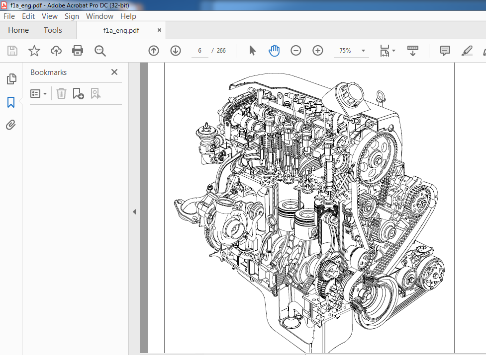
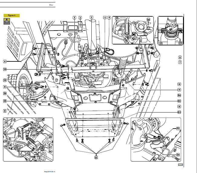
IMAGES PREVIEW OF THE MANUAL:

FILE DETAILS:
Iveco FIA Engine Repair Manual – PDF DOWNLOAD
Format: PDF
Language: English
Brand: Iveco
DESCRIPTION:
Iveco FIA Engine Repair Manual – PDF DOWNLOAD
MAIN OPERATIONS ON ENGINE MOUNTED ON VEHICLE:
Keep to the following instructions before doing any work on the engine involving components of the fuel supply system.
– Before doing any work on the engine, perform the engine/vehicle fault diagnosis with specific IVECO diagnosis equipment and print out the results.
– Replacement of the MS6.3 or EDC 16control unit must be authorized by the Help Desk.
– Following components in feed system cannot be overhauled but have to be replaced: pressure relief valve, if present, fuel pressure sensor, hydraulic accumulator, completeCP1 high pressure feed pump, pressure control valve, electric injectors.
– All the parts of the Common Rail system are packaged by the supplier in sheets of oiled paper and are stored in cardboard boxes. They must therefore be protected against moisture and unpacked just prior to assembly.
– The greatest care must be taken over the cleanliness of parts, making sure that when handling or assembling(starting with straightforward filter and pre-filter replacement) no dirt of foreign bodies can get inside. For this reason, the plugs protecting the hydraulic parts and sensors must be removed just prior to positioning in their seats.
– Take care over the direction of assembly for all electrical connections.
– All threaded connections must be tightened to the prescribed torque.
– All the quick-coupling connectors (on the engine they are found on the high-pressure pump and on the diesel drain
manifold) must be fully inserted. To drive them out, press on the tabs at the base of the connectors.
TABLE OF CONTENTS:
Iveco FIA Engine Repair Manual – PDF DOWNLOAD
MAIN OPERATIONS ON ENGINE MOUNTED
ON VEHICLE 291
ENGINE REMOVAL-REFITTING 293
– Removal 293
– Refitting 297
– Checks and tests 297
– Power steering system air bleed 297
REPLACING BELTS 298
– Replacing air-conditioning compressor drive belt
(version with belt tensioner) 298
– Disassembly 298
– Assembly and adjusting belt tension 298
– Replacing air-conditioning compressor drive belt
(version with elastic belt) 298
– Disassembly 298
– Assembly 298
– Power steering pump-alternator belt replacement 298
– Disassembly 298
– Assembly 298
– Replacing timing drive belt 299
– Disassembly 299
– Assembly 300
REPLACING ELECTRO-INJECTORS 301
– Disassembly 301
– Assembly 301
CYLINDER HEAD REMOVAL AND REFITTING 302
– Removal 302
– Refitting 304
REPLACING HIGH-PRESSURE PUMP CP3 305
– Removal 305
– Refitting 305
REPLACING WATER PUMP 305
– Removal 305
Revi – February 2005
288 F1A ENGINE DAILY
Base – May 2004 Print 603 93 281/A
Page
Print 603 93 281/A
– Refitting 305
EMISSIONS 306
ENGINE IDENTIFICATION CODE 308
CHARACTERISTIC CURVES 308/1
GENERAL SPECIFICATIONS 310
ASSEMBLY DATA — CLEARANCES 313
TOOLS 318
EXPERIMENTAL TOOLS 323
TIGHTENING TORQUE 334
OVERHAULING ENGINE F1A 339
DISASSEMBLING THE ENGINE AT THE BENCH 339
REPAIRS 348
CYLINDER BLOCK 348
– Checks and measurements 348
– Checking head mating surface on cylinder block 349
CRANKSHAFT 349
– Measuring main journals and crank pins 349
– Checking crankshaft 350
– Replacing timing control gear 352
ENGINE ASSEMBLY 352
– Assembling main bearings 352
– Measuring main journal assembly clearance 352
– Checking crankshaft end float 353
– Assembling rear seal 354
– Replacing bearing supporting gearbox input shaft 355
ENGINE FLYWHEEL 355
CONNECTING ROD — PISTON ASSEMBLY 355
– Pistons 356
– Measuring piston diameter 356
– Piston pins 357
– Conditions for correct pin-piston coupling 357
– Piston rings 357
– Connecting rods 358
– Bushes 359
Page
– Checking connecting rods 359
– Checking torsion 359
– Checking bending 359
– Assembling connecting rod-piston assembly 359
– Checking for connecting rod — piston distortion 360
– Assembling piston rings 360
– Assembling connecting rod — piston assemblies
in cylinder barrels 360
– Measuring crankpin assembly clearance 361
– Checking piston protrusion 361
CYLINDER HEAD 362
– Disassembly 362
– Removing valves 362
– Checking cylinder head seal 363
– Checking cylinder head mating surface 363
VALVES 363
– Removing deposits, refacing and checking valves 363
– Checking clearance between valve stem and
valve guide and centring valves 364
VALVE GUIDES 364
– Replacing valve guides 364
– Boring valve guides 364
VALVE SEATS 365
– Regrinding – replacing valve seats 365
VALVE SPRINGS 366
ROCKER ARMS — TAPPETS 366
– Checks 367
ASSEMBLING CYLINDER HEADS 367
– Overhead 368
– Overhead removal 368
TIMING SYSTEM 369
– Description 369
– Camshaft 370
– Checks 370
– Checking cam lift and pin alignment 370
Revi – February 2005
DAILY F1A ENGINE 289
Print 603 93 281/A Base – May 2004
Page
– Assembling overhead 371
– Assembling front seal ring 372
– Refitting cylinder head 375
– Adjusting air-conditioner —
compressor drive belt tension 378
– Timing speed sensor 382
– Engine speed sensor 382
LUBRICATION 383
– General 383
OIL VACUUM PUMP ASSEMBLY (GPOD) 385
– Oil pump 385
– Characteristic data 385
– Vacuum pump 385
– Oil pressure control valve 386
– Oil filter 386
– Modine heat exchanger 386
– Oil vapour recirculation system 387
– Description 387
COOLING 388
– Description 388
– Operation 388
– Electromagnetic pulley 389
– Water pump 389
– Thermostat 389
TURBOCHARGING 390
– Description 390
– Turbocharger 391
REPAIRS 392
– Pressure relief valve 392
– Checking and adjusting pressure relief valve 392
– Replacing pressure relief valve 392
EXHAUST GAS RECIRCULATION (EGR) SYSTEM 393
– EGR system operation 393
Page
– Operating principles 393
– Air flow meter 394
FUEL SUPPLY 395
HIGH-PRESSURE ELECTRONIC
INJECTION SYSTEM (MS 6 3 – EDC 16) 395
– General 395
SYSTEM OPERATION 397
– Self-diagnosis — BLINK CODE 397
– Immobilizer recognition 397
– Checking fuel temperature 397
– Checking engine coolant temperature 397
– Checking quantity of fuel injected 397
– Checking idling adjustment 397
– Fuel cut-off in release phase 397
– Checking cylinder balancing on idling 397
– Checking regular engine rotation (anti-sawing) 397
– Checking smokiness at exhaust on acceleration 397
– Checking exhaust gas recirculation
(E G R if present) 397
– Checking top speed limit 397
– Checking regular rotation on acceleration 397
– Checking glow plug control unit 397
– Checking activation of air-conditioning system 397
– Checking fuel pump 397
– Checking diesel warming 398
– Checking cylinder position 398
– Checking pilot and main injection timing 398
– Checking injection pressure closed cycle 398
– Fuel supply 398
– Correcting flow rate according
to water temperature 398
– Correcting flow rate to avoid noise,
smoke or overloading 398
Revi – February 2005
290 F1A ENGINE DAILY
Base – May 2004 Print 603 93 281/A
Page
– De-rating 398
– Injection timing electronic test 398
– Speed governor 398
– Engine starting 398
– Cold starting 399
– Warm starting 399
– Run up 399
– After run 399
– Cut-off 399
– Cylinder balancing 399
– Synchronization search 399
OPERATION 401
HYDRAULIC SYSTEM 403
– Fuel pump 403
– Specifications 403
– Fuel filter 404
– Tightening torques 404
– Fuel pipes 404
– High-pressure pump 405
– High-pressure pump internal structure 407
– Working principle 408
– Pressure control valve 411
– Replacing pressure regulator 411
MECHANICAL SUPPLY PUMP 412
– Hydraulic accumulator (rail) 413
– Overpressure valve
(for forged hydraulic accumulator) 413
ELECTRO-INJECTORS 413
– Operation 414
ELECTRIC/ELECTRONIC COMPONENTS 414
– Electronic control unit MS6 3 or EDC 16 414
– Glow plug electronic control unit 415
– Glow plugs 415
SENSORS 415
Page
– Engine speed sensor 415
– Camshaft timing sensor 415
– Air temperature and pressure sensor 415
– Fuel temperature sensor 415
– Fuel pressure sensor 415
– Atmospheric pressure sensor 415
– Engine coolant temperature sensor 416
– Throttle pedal position sensor 416
– Clutch pedal position sensor 416
– Brake pedal position sensor 416
– Vehicle speed sensor 416
ACTUATORS 416
– PWM (Pulse Width Modulation) controls 416
GUIDE TO TROUBLESHOOTING 417
PLEASE NOTE:
- This is the SAME MANUAL used by the dealerships to diagnose your vehicle
- No waiting for couriers / posts as this is a PDF manual and you can download it within 2 minutes time once you make the payment.
- Your payment is all safe and the delivery of the manual is INSTANT – You will be taken to the DOWNLOAD PAGE.
- So have no hesitations whatsoever and write to us about any queries you may have : heydownloadss @gmail.com


Eliel –
Very quick