

Iveco EuroCargo Tector 6t-10t Repair Manual – PDF DOWNLOAD
FILE DETAILS:
Iveco EuroCargo Tector 6t-10t Repair Manual – PDF DOWNLOAD
Format: PDF
Language: English
Brand: Iveco
DESCRIPTION:
Iveco EuroCargo Tector 6t-10t Repair Manual – PDF DOWNLOAD
EUROCARGO TECTOR
6 TO 10 t
REPAIR MANUAL
FOREWORD:
”This document provides data, characteristics, instructions and methodology to perform repair interventions on the vehicle and its components. Anyhow, this document is addressed to qualified and specialised personnel. Iveco commercial and assistance network personnel as well as all Iveco authorised points of assistance are specifically qualified and equipped to perform the repair interventions that are indicated in this document. Before performing any intervention, check to have available the document relating to the vehicle model on which the intervention is being performed and also make sure that all accident prevention devices, such as, as a rough guide, goggles, helmet, gloves, shoes, as well as work tooling, lifting and transport tooling, etc., are available and efficient, and further make sure that the vehicle is put such a way that an intervention can be made in safety conditions.
- Making interventions strictly observing the indications given here, as well as using specific tooling indicated, assures a correct repair intervention, execution timing observance and operators’ safety. Each repair intervention must be finalised to the recovery of functionality, efficiency and safety conditions that are provided by Iveco. Each intervention, on the vehicle, that is finalised to a modification, alteration or else, which is not authorised by Iveco, involves the exclusion of any responsibility for Iveco, and, in particular, where the vehicle is covered by a guarantee, each such intervention involves an immediate lapse of the guarantee.
- Responsibility for Iveco in repair intervention execution is excluded. Iveco is available to provide all clarifications necessary tomake interventions, as well as to provide indications in cases and situations not included in this document. Data and information contained in this document could result not to be updated owing to modifications made by Iveco at any moment for technical or commercial reasons, or because of the need to adapt the vehicle to law requirements in different countries.
- In the case of a difference between what contained here and what actually found on the vehicle, please contact Iveco network before making any intervention.” The data contained in this publication might fail to reflect the latest changes which the Manufacturer may introduce at any time, for technical or sales purposes, or to meet the requirements of local legislation. Copy, even partial, of text and drawings is forbidden.
TABLE OF CONTENTS:
Iveco EuroCargo Tector 6t-10t Repair Manual – PDF DOWNLOAD
EUROCARGO TECTOR 6 TO 10 t 1
REPAIR MANUAL 1
PRELIMINARY REMARKS 3
SYMBOLS -WARNINGS 3
SYMBOLS – ASSISTANCE OPERATIONS 4
PRODUCT CODE 5
GENERAL WARNINGS 6
GENERAL WARNINGS ON THE ELECTRIC SYSTEM 8
Bonding and screening 9
OPTIONAL ELECTRICAL AND MECHANICAL PARTS INSTALLATIONS 10
CONVERSIONS BETWEEN THE MAIN UNITS OF MEASUREMENT OF THE INTERNATIONAL SYSTEM AND MOST USED DERIVED QUANTITIES 10
UPDATE DATA 11
INDEX OF SECTIONS 13
SECTION 1 – General Specifications 15
General Specifications 15
COMPOSITION OF THE MODELS 17
IDENTIFICATION DATA AND LOCATION ON VEHICLE 25
FILLING UP 26
INTERNATIONAL LUBRICANT DESIGNATION 27
SECTION 2 – Engine 29
Engine 29
Engine 29
ENGINE IDENTIFICATION CODE 31
MAIN SERVICING OPERATIONS TO BE PERFORMED ON ENGINE FITTED ON VEHICLE 32
WARNINGS 32
High pressure CP3 pump 32
Rail and fittings 32
Injector 32
Low pressure tubing 32
High pressure tubing 32
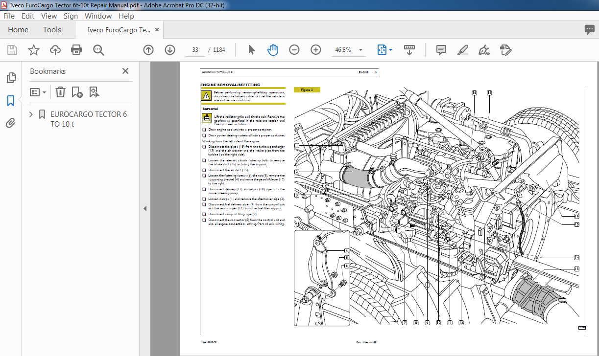
ENGINE REMOVAL/REFITTING 33
Removal 33
Refitting 35
Checks and inspections 35
Topping up the engine cooling system 35
Bleeding air from the fuel system 36
Bleeding air from the power steering system 36
INJECTOR REPLACEMENT 37
Removal 37
Refitting 37
Checks and inspections 39
REPLACEMENTOFENGINE FRONTSHAFT COVER SEALING RING 39
REPLACEMENT OF FLYWHEEL CASE SEALING RING 40
CYLINDER HEAD REMOVAL/REFITTING 41
Removal 41
Refitting 43
Checks and inspections 43
Engine F4 AE 0481 47
GENERAL SPECIFICATIONS 49
CLEARANCE DATA 52
TIGHTENING TORQUE 58
AUXILIARY COMPONENTS 60
TOOLS 60
ENGINE OVERHAUL 68
ENGINE REMOVAL AT THE BENCH 68
REPAIR OPERATIONS 76
CYLINDER UNIT 76
Checks and measurements 76
Checking head supporting surface on cylinder unit 77
TIMING SYSTEM 77
Camshaft 77
Checking cam lift and pin alignment 78
BUSHES 78
Bush replacement 79
Tappets 79
Fitting tappets — camshaft 79
OUTPUT SHAFT 80
Measuring journals and crankpins 80
Replacing oil pump control gear 82
Fitting main bearings 82
Finding journal clearance 82
Checking output shaft shoulder clearance 83
CONNECTING ROD – PISTON ASSEMBLY 83
Pistons 84
Measuring piston diameters 84
Piston pins 85
Conditions for proper pin-piston coupling 85
Split rings 85
Connecting rods 86
Bushes 86
Checking connecting rods 87
Checking torsion 87
Checking bending 87
Fitting connecting rod-piston assembly 87
Connecting rod-piston coupling 87
Fitting split rings 88
Fitting connecting rod-piston assembly into cylinder barrels 88
Finding crankpin clearance 89
Checking piston protrusion 90
Timing gear case 90
Timing 91
Flywheel housing 91
ENGINE FLYWHEEL 92
Replacing engine flywheel ring gear 92
CYLINDER HEAD 96
Removing the valves 96
Checking cylinder head wet seal 97
Checking cylinder head supporting surface 97
VALVES 98
Removing carbon deposits, checking and grinding valves 98
Checking clearance between valve stem and valve guide and valve centering 98
VALVE GUIDE 99
VALVE SEATS 99
Regrinding – replacing the valve seats 99
VALVE SPRINGS 101
FITTING CYLINDER HEAD 101
Refitting the cylinder head 101
Assembling electro-injectors 102
RODS 103
Rocker assembly 103
Adjusting tappet clearance 104
Intake manifold 105
Wiring support 107
LUBRICATION 111
OIL PUMP 113
HEAT EXCHANGER 113
Oil pressure relief valve 114
Oil vapour recycling 115
COOLING SYSTEM 117
Water Pump 119
Viscous fan 119
Thermostat 120
BOOSTER 120
Turbosupercharger 120
Description 120
TURBOSUPERCHARGER ACTUATOR 121
Check and adjustment 121
Actuator replacement 121
TURBOSUPERCHARGER LAYOUT 123
COMMON RAIL 125
General Specifications 125
HYDRAULIC SYSTEM 127
HYDRAULIC SYSTEM LAYOUT 129
FUEL PREFILTER 131
FUEL FILTER 131
MECHANICAL SUPPLY PUMP 132
Normal operating conditions 132
Overpressure condition at outlet 132
Drain conditions 132
CP3 HIGH-PRESSURE PUMP 133
HIGH-PRESSURE PUMP – INSIDE STRUCTURE 134
Operating principle 135
Operation 137
RAIL 137
DOUBLE STAGE OVERPRESSURE VALVE 138
INJECTOR 139
Injector in rest position 139
Injection start 139
Injection end 139
PRESSURE LIMITER FOR FUEL RETURN 139
Engine F4 AE 0681 143
GENERAL SPECIFICATIONS 145
ASSEMBLY DATA – CLEARANCES 148
ENGINE F4AE0681 OVERHAUL 156
Engine removal at the bench 156
TIMING SYSTEM 157
Camshaft 157
BUSHES 157
CYLINDER HEAD VALVE SEATS 159
Cylinder head fastening screw tightening 161
LUBRICATION 163
COOLING SYSTEM 164
BOOSTER 165
TURBOSUPERCHARGER LAYOUT 167
Troubleshooting guide 169
FOREWORD 171
Diagnosis through instruments 171
DIAGNOSTICS 173
SECTION 3 – Clutch 183
Clutch 183
DESCRIPTION 185
Clutch 185
SPECIFICATIONS AND DATA 185
DIAGNOSTICS 188
TIGHTENING TORQUES 191
TOOLS 191
REMOVAL AND REFITTING 192
Removal 192
Refitting 192
DRIVEN PLATE OVERHAUL 192
Damper hub check 192
Friction gaskets 192
THRUST BEARING REMOVAL – REFITTING 193
REPLACING CLUTCH SHAFT SUPPORT BEARING 193
HYDRAULIC CONTROL 194
Mini servo-clutch 194
Connections 194
Clutch disengaging cylinder 194
Clutch mounting assembly 195
Clutch wear control 195
ADJUSTING PEDAL AND STOP POSITION SCREWS 196
Clutch pedal clearance 196
Clutch pedal travel 196
CLUTCH CONTROL DRAIN PROCEDURE 196
SECTION 4 – Gearboxes 197
Gearboxes 197
DIAGNOSTICS 199
Gears control connection 201
Gearbox control tie-rods adjustment 201
Gearbox 2855S 5 – 2855S 6 203
DESCRIPTION 205
SPECIFICATIONS AND DATA 206
TIGHTENING TORQUES 209
TOOLS 210
GEARBOX 2855S 6 REMOVAL – REFITTING 215
Removal 215
Refitting 215
GEARBOX DISASSEMBLY 217
Checks 220
GEARBOX ASSEMBLY 221
Bearings pre-load adjustment for secondary shaft 221
PRIMARY SHAFT DISASSEMBLY 227
PRIMARY SHAFT ASSEMBLY 229
MOTION INLET SHAFT DISASSEMBLY 232
MOTION INLET SHAFT ASSEMBLY 232
Motion inlet shaft bearing adjustment 232
SECONDARY SHAFT DISASSEMBLY 233
SECONDARY SHAFT ASSEMBLY 233
INTERNAL DRIVE SHAFT DISASSEMBLY 233
INTERNAL DRIVE SHAFY ASSEMBLY 233
EXTERNAL CONTROL SHAFT DISASSEMBLY 234
EXTERNAL CONTROL BOX ASSEMBLY 235
Idle-R M switch adjustment 237
Gearbox 2865S 6 239
DESCRIPTION 241
SPECIFICATIONS AND DATA 243
TIGHTENING TORQUES 245
TOOLS 246
GEARBOX 2865S 5 DISENGAGEMENT/ RE-ENGAGEMENT 251
Disengagement 251
Re-engagement 251
GEARBOX DISASSEMBLY 253
Rear cover sealing gasket replacement 256
Checks 257
GEARBOX ASSEMBLY 257
Bearings pre-loading adjustment for secondary shaft 258
PRIMARY SHAFT DISASSEMBLY 262
PRIMARY SHAFT ASSEMBLY 265
MOTION ENTRY SHAFT ASSEMBLY 268
SECONDARY SHAFT DISASSEMBLY 268
SECONDARY SHAFT ASSEMBLY 268
INTERNAL CONTROL SHAFT DISASSEMBLY 269
INTERNAL CONTROL SHAFT ASSEMBLY 269
EXTERNAL CONTROL SHAFT DISASSEMBLY 269
EXTERNAL CONTROL BOX ASSEMBLY 270
Idle-R M switch adjustment 272
Gearbox 2870S 9 273
DESCRIPTION 275
SPECIFICATIONS AND DATA 276
TIGHTENING TORQUES 279
TOOLS 280
GEARBOX 2870S 9 DISENGAGEMENT/RE-ENGAGEMENT 285
Disengagement 285
Re-engagement 285
GEARBOX DISASSEMBLY 287
Checks 291
GEARBOX ASSEMBLY 292
Bearings pre-load adjustment for secondary shaft 292
Idle-Reverse Gear switch adjustment 298
PRIMARY SHAFT DISASSEMBLY 299
PRIMARY SHAFT ASSEMBLY 301
MOTION INLET SHAFT DISASSEMBLY 301
MOTION INLET SHAFT ASSEMBLY 302
Motion inlet shaft bearing adjustment 302
SECONDARY SHAFT DISASSEMBLY 302
SECONDARY SHAFT ASSEMBLY 302
INTERNAL DRIVE SHAFT DISASSEMBLY 302
INTERNAL DRIVE SHAFT ASSEMBLY 303
EXTERNAL DRIVE CASE DISASSEMBLY 303
EXTERNAL CONTROL BOX ASSEMBLY 304
EPICYCLIC REDUCTION GEAR ASSEMBLY 307
Operating diagrams about pneumatic epicyclic reduction gear drive circuit 307
DISASSEMBLY 309
Checks 311
ASSEMBLY 312
SECTION 5 – Propeller shafts 317
Propeller shafts 317
DESCRIPTION 319
SPECIFICATIONS AND DATA FOR ”FIXED” AND ”SLIDING” PROPELLER SHAFTS 323
SPECIFICATIONS AND DATA FOR ”SINGLE-SECTION” PROPELLER SHAFTS 324
DIAGNOSTICS 325
TIGHTENING TORQUES 325
SINGLE-SECTION PROPELLER SHAFT DISENGAGEMENT – RE-ENGAGEMENT 326
Disengagement 326
Re-engagement 326
SLIDING PROPELLER SHAFT DISENGAGEMENT – RE-ENGAGEMENT 327
Disengagement 327
Re-engagement 327
TWO-SECTION PROPELLER SHAFT DISENGAGEMENT – RE-ENGAGEMENT 327
CHECK OF VEHICLE PROPELLER SHAFTS 327
SECTION 6 – Rear axles 4517 and 4521 329
Rear axles 4517 and 4521 329
DESCRIPTION 331
SPECIFICATIONS AND DATA 333
DIAGNOSTICS 335
TIGHTENING TORQUES 337
TOOLS 341
REAR AXLE DISENGAGEMENT/RE-ENGAGEMENT (with mechanical suspensions) 345
Disengagement 345
Re-engagement 345
REAR AXLE DISENGAGEMENT/RE-ENGAGEMENT (with pneumatic suspensions) 346
Disengagement 346
Re-engagement 346
REAR AXLE ASSEMBLY REVISION 347
AIR VENT DISENGAGEMENT – RE-ENGAGEMENT 347
WHEEL HUB REVISION 348
Disassembly 348
Check of parts composing wheel hubs 349
Rear axle case check 350
Assembly 351
DIFFERENTIAL GEAR REPAIR 353
Disassembly pertaining to rear axle 4517 354
Disassembly pertaining to rear axle 4521 354
Gearing case disassembly 354
Disassembly of bevel pinion assembly 355
Check of parts composing the differential gear 356
Gearing case assembly 357
Assembly pertaining to rear axle 4521 360
Assembly pertaining to rear axle 4521 362
Gearing case assembly on rear axle case 362
Assembly pertaining to rear axle 4517 362
Assembly pertaining to rear axle 4521 362
VARIATION WITH DIFFERENTIAL LOCKING 366
Disassembly 367
Checks 367
Assembly 367
ANTISKID DEVICE SENSOR 367
Assembly 367
SECTION 7 – Front axles 5833 – 5833/1 369
DESCRIPTION 371
Front axle 371
Characteristic angles 373
SPECIFICATIONS AND DATA 375
DIAGNOSTICS 377
TIGHTENING TORQUES 380
TOOLS 381
FRONT AXLE DISENGAGEMENT/RE-ENGAGEMENT (with mechanical suspensions) 385
Disengagement 385
Re-engagement 385
FRONT AXLE DISENGAGEMENT/RE-ENGAGEMENT (with pneumatic suspensions) 386
Disengagement 386
Re-engagement 386
FRONT WHEEL ATTITUDE 387
Claws and projectors placement 387
Electronic rim misalignment compensation 388
Wheel alignment 388
Wheel toe-in check 389
Wheel camber check 389
King pin and caster angle check 389
Steering angles check 390
FRONT AXLE ASSEMBLY REVISION 391
WHEEL HUBS DISENGAGEMENT AND RE-ENGAGEMENT 391
Disengagement 391
Sealing ring replacement 392
Wheel hubs re-engagement 392
Axial clearance adjustment for wheel hub bearings 392
Rolling torque measure 393
WHEEL HUB BEARINGS REPLACEMENT 393
WHEEL SECURING RISERS REPLACEMENT 394
TRANSVERSE TIE-ROD DETACHMENT AND RE-ATTACHMENT 394
Detachment 394
Re-attachment 394
TRANSVERSE TIE-ROD STUB AXLE REPLACEMENT 395
TRANSVERSE TIE-ROD LEVERS DETACHMENT AND RE-ATTACHMENT 395
LONGITUDINAL TIE-ROD LEVER DETACHMENT AND RE-ATTACHMENT 395
STUB AXLE PIN DETACHMENT AND RE-ATTACHMENT 395
Detachment 395
Re-attachment 396
Check and adjustment of clearance between stub axle and front axle 397
STEERING KNUCKLE PIN BEARING REPLACEMENT 398
FRONT AXLE BODY CHECKS AND MEASURES 399
Planarity check of leaf springs bearing surfaces with respect to stub axle pin holes 399
Check of stub axle pin holes camber 400
SECTION 8 – Suspensions 401
Front and rear mechanical suspensions 403
DESCRIPTION 405
FRONT LEAF SPRINGS 405
FRONT PARABOLIC LEAF SPRING SPECIFICATIONS AND DATA 406
Models 60E – 100E with axle load up to 3400 kg 406
Models 65E – 100E with axle load over 3400 kg 407
FRONT HALF-ELLIPTIC LEAF SPRING SPECIFICATIONS AND DATA 408
Models 60E K 408
Models 65E K – 75E K 409
Models 75E15K 410
Models 80E K – 100E K 411
REAR LEAF SPRINGS 412
REAR PARABOLIC LEAF SPRING SPECIFICATIONS AND DATA 414
Models 60E – 65E – 75E – 80E 414
Models 100E 415
REAR HALF-ELLIPTIC LEAF SPRING SPECIFICATIONS AND DATA 416
Models 60E K – 65E K 416
Models 75E K 417
Models 80E K 418
Models 100E K 419
SHOCK ABSORBERS 420
Assembly diagrams 420
SHOCK ABSORBER SPECIFICATIONS AND DATA 421
Front shock absorbers (with parabolic leaf springs) 421
Front shock absorbers (with half-elliptic leaf springs) 421
Rear shock absorbers (with parabolic leaf springs) 422
Rear shock absorbers (with half-elliptic leaf springs) 422
DIAGNOSTICS 423
TIGHTENING TORQUES 427
TOOLS 427
FRONT MECHANICAL SUSPENSIONS DISENGAGEMENT – RE-ENGAGEMENT 429
Disengagement 429
Re-engagement 429
REAR MECHANICAL SUSPENSIONS DISENGAGEMENT – RE-ENGAGEMENT 430
Disengagement 430
Re-engagement 430
FRONT SHOCK ABSORBERS 431
Disengagement 431
Re-engagement 431
REAR SHOCK ABSORBERS 431
Disengagement 431
Re-engagement 431
FRONT STABILISING BAR 431
Disengagement 431
Re-engagement 431
REAR STABILISING BAR 432
Disengagement 432
Re-engagement 432
REPAIR INTERVENTIONS 432
REPLACING LEAF-SPRING BUSHINGS (For vehicles with leaf-springs provided with bushings having a metal shell) 432
DISCONNECTING AND RECONNECTING REAR LEAF-SPRING BUSHINGS 432
Disconnecting rear bushings 432
Reconnecting rear bushings 435
Disconnecting front bushings 436
Reconnecting front bushings 436
DISCONNECTING AND RECONNECTING FRONT LEAF-SPRING BUSHINGS 437
Disconnecting front bushings 437
Reconnecting front bushings 438
Disconnecting rear bushings 438
Reconnecting front bushings 439
Front and rear pneumatic suspensions 441
PNEUMATIC SUSPENSIONS 443
IN GENERAL 443
PNEUMATIC SUSPENSIONS ASSEMBLIES 444
Principle layout for rear pneumatic suspensions 445
Principle layout for FULL pneumatic suspensions 446
MAIN COMPONENTS ARRANGEMENT ON VEHICLE 447
CHASSIS LIFTING, LOWERING AND SELF-LEVELING 448
Remote control 448
REMOTE CONTROL DESCRIPTION AND OPERATION 449
Chassis lifting/lowering 449
Chassis self-leveling 449
”M 1” – ”M 2” level 449
DIAGNOSTICS 450
TIGHTENING TORQUES 452
HENDRICKSON type rear pneumatic suspension 452
TOOLS 453
SPECIFICATIONS AND DATA 454
Pneumatic system 454
FRONT LEAF SPRING (MODELS ML 80E18FP/21FP – ML90E18FP/21FP – ML 100E18FP/21FP) 455
Front shock absorbers 456
Rear shock absorbers 456
MAIN PNEUMATIC SYSTEM COMPONENTS 457
Controlled-pressure valve 457
Level sensor 457
Front axle electro-pneumatic distributor for 4 x 2 FP vehicles 458
Operation 458
Front axle lifting 458
Front axle lowering 458
Self-leveling 458
Rear axle electropneumatic distributor for 4 x 2 P/FP vehicles 459
Operation 459
Rear axle lifting 459
Rear axle lowering 459
Self-leveling 459
MANOMETRIC LOW AIR PRESSURE SWITCH 460
AIR SPRINGS 460
Electronic unit 460
FRONT PNEUMATIC SUSPENSIONS DISENGAGEMENT – RE-ENGAGEMENT 461
Disengagement 461
Re-engagement 461
NEWAY TYPE REAR PNEUMATIC SUSPENSIONS DISENGAGEMENT – RE-ENGAGEMENT 462
Disengagement 462
Re-engagement 462
FRONT SHOCK ABSORBERS 463
Disengagement 463
Re-engagement 463
FRONT AIR SPRINGS 463
Disengagement 463
Re-engagement 463
REAR SHOCK ABSORBERS 463
Disengagement 463
Re-engagement 463
REAR AIR SPRINGS 464
Disengagement 464
Re-engagement 464
FRONT STABILISING BAR 464
REAR STABILISING BAR 464
SECTION 9 – Wheels and tyres 465
Wheels and tyres 465
DESCRIPTION 467
SPECIFICATIONS AND DATA 467
Tire pressure values 467
TOOLS 468
DIAGNOSTICS 468
STATIC WHEEL BALANCING 471
CORRECTION OF RESIDUAL STATIC UNBALANCE 472
TIRE PRESSURE 472
TIRE BEHAVIOUR DEPENDING ON PRESSURE 473
SECTION 10 – Steering system 475
Steering system 475
DESCRIPTION 477
Hydraulic guide system installation view 477
SPECIFICATION AND DATA 477
STEERING WHEEL CONTROL SCHEME 478
DIAGNOSTIC 479
TIGHTENING TORQUE 484
TOOLS 484
POWER STEERING PUMP ZF FN4 Integral 485
Description 485
ZF 8090 HYDRAULIC POWER STEERING 486
Description 486
Hydraulic steering limiting device 489
REMOVING AND REFITTING THE HYDRAULIC POWER STEERING (ZF 8090) 490
Removal 490
Refitting 491
ADJUSTING THE HYDRAULIC STEERING LIMITING DEVICE 492
TRW TAS 30 HYDRAULIC POWER STEERING 493
Description 493
Neutral position – straight running 494
Steering to the right 495
Steering to the left 496
HYDRAULIC STEERING LIMITING DEVICE 497
Setting the TRW TAS 30 power steering limiting device automatic adjustment 498
Checking the automatic adjustment 498
Fluid leaking manual adjustment 499
BLEEDING THE AIR FROM THE HYDRAULIC POWER STEERING CIRCUIT 500
MEASURING CLEARANCE IN STEERING BOX AT STEERING WHEEL 500
CHECKING MAXIMUM PRESSURE OF POWER STEERING SYSTEM 500
SECTION 11 – Pneumatic System – Brakes 501
Pneumatic System – Brakes 501
SYMBOLS FOR AIR/HYDRAULIC SYSTEM CIRCUIT DIAGRAMS (MISCELLANEOUS AND GENERATORS) 505
SYMBOLS FOR AIR/HYDRAULIC SYSTEM CIRCUIT DIAGRAMS (VALVES) 506
SYMBOLS FOR AIR/HYDRAULIC SYSTEM CIRCUIT DIAGRAMS (TANKS AND ACCUMULATORS) 512
SYMBOLS FOR AIR/HYDRAULIC SYSTEM CIRCUIT DIAGRAMS (CONVERTERS, CYLINDERS AND CALLIPERS) 513
SYMBOLS FOR AIR/HYDRAULIC SYSTEM CIRCUIT DIAGRAMS (CYLINDERS AND CALLIPERS) 514
SYMBOLS FOR AIR/HYDRAULIC SYSTEM CIRCUIT DIAGRAMS (HALF-JOINTS AND COUPLING HEADS) 515
SYMBOLS FOR AIR/HYDRAULIC SYSTEM CIRCUIT DIAGRAMS (INDICATORS AND SWITCHES) 517
SYMBOLS FOR AIR/HYDRAULIC SYSTEM CIRCUIT DIAGRAMS (BRAKES) 518
PIPES AND COUPLINGS 519
Overview 519
End forming on rigid pipes 519
Bending rigid pipes 520
Cutting rigid pipes 520
Replacing flexible hoses with threaded couplings 521
Replacing flexible hoses with quick connection couplings 522
BRAKING SYSTEM 524
General layout for stand-alone vehicles 524
General layout for towing vehicles 525
BRAKING SYSTEM MAIN COMPONENTS LAYOUT ON VEHICLE 526
Description 527
Service braking 527
Exhaust brake 527
Operation 527
Parking brake 527
Brakes 527
Front and rear brakes 527
DIAGNOSTIC 528
TIGHTENING TORQUE 539
TOOLS 540
SPECIFICATIONS AND DATA – PNEUMATIC SYSTEM 543
Compressor 543
A P U (drier/4 ways) 543
Drier 543
4-way protection valve 543
Air tanks 543
Duplex distributor 543
Pressure limiting valve (for towable vehicles) 543
Augmenter valve (towing vehicles) 544
Triple control servo distributor (towing vehicles) 544
Variable and automatic coupling heads 544
Air/hydraulic converters 544
Manual discharge valve 544
Parking brake distributor (single vehicles) 545
Parking brake distributor (vehicles adapted for towing) 545
Dump valve 545
Spring cylinder 545
ABS electronic control unit 545
ABS solenoid valve 545
SPECIFICATIONS AND DATA – BRAKES 546
BRAKE SYSTEM MAIN COMPONENT CHECKS 547
BRAKING SYSTEM MAIN COMPONENTS 550
COMPRESSOR 550
Diagnostic 550
A P U (Air Processing Unit) 551
Operation 552
Diagnostics 553
ENGINE BRAKE SWITCH 554
ENGINE BRAKE SOLENOID VALVE 554
ENGINE BRAKE CONTROL OPERATING CYLINDER 554
MANUAL DISCHARGE VALVE 554
SAFETY VALVE (Optional) 555
DUPLEX DISTRIBUTOR 555
Brake release 556
Diagnostic 556
PRESSURE LIMITING VALVE 557
Operation 557
Pressure limiting 557
Setting at the bench 557
Diagnostic 557
TRIPLE CONTROL SERVO DISTRIBUTOR 558
Predominance regulation 558
Diagnostic 558
COUPLING HEADS 559
Operation 559
CHECK VALVE 559
Operation 559
AIR/HYDRAULIC CONVERTERS (diaphragm) 560
Master cylinder 560
Checks 560
Refitting 560
Diagnostic 561
AUGMENTER VALVE (towing vehicles) 561
Diagnostic 561
ANTI-SKID SYSTEMS 562
Antilock braking system (ABS) 562
ELECTROPNEUMATIC VALVE 562
Operation 562
ELECTRONIC CONTROL UNIT 563
Operation 563
RPM SENSORS 563
PHONIC WHEELS 563
Operation 563
AIR BLEEDING FROM HYDRAULIC CIRCUIT 564
Front brake circuit 564
Rear brake circuit 564
Air bleeding from the hydraulic circuit using the deaerating device 564
PARKING BRAKE CONTROL HAND DISTRIBUTOR (stand-alone vehicles) 565
Diagnostic 565
PARKING BRAKE CONTROL HAND DISTRIBUTOR (Towing vehicles) 566
Diagnostic 566
SPRING BRAKE CYLINDER 567
Operation 567
Spring cylinder emergency brake release device 567
Resetting the rear brakes in running condition 568
Repair operations 568
Diagnostic 568
REPAIRING BRAKES 569
Front brakes 569
Operation 569
REPLACING FRONT BRAKE LININGS 569
For 5833/1 front axle 570
For any model 570
For 5833 front axle 571
For 5833/1 front axle 571
REMOVING FRONT BRAKE CALLIPERS 572
For any model 572
REMOVING FRONT WHEEL HUBS 572
OVERHAULING THE BRAKE DISCS 573
TURNING AND GRINDING THE BRAKE DISCS 573
Rear brakes 574
Operation 574
REAR BRAKE CALLIPER HYDRAULIC OPERATION DIAGRAM (GIRLING) 574
Parking brake device operation 574
Automatic backlash take up device operation 574
Operation of the system for taking up wear 576
First operation stage (F1 < F2) – Low pressure 577
Second operation stage (F1 > F2) – High pressure 578
Third operation stage (Pressure resetting to zero) – Resting position 579
Parking braking 580
Parking brake operation 580
REPLACING THE REAR BRAKE LININGS 581
Removal 581
For rear axle 4517 581
For any model 582
Refitting 583
For rear axle 4521 583
For rear axle 4517 583
REMOVING THE REAR BRAKE CALLIPERS 583
REMOVING REAR WHEEL HUBS 584
OVERHAULING THE BRAKE CALLIPERS 585
Brake callisper removal 587
For rear calliper 587
For front and rear calliper 588
For rear calliper 588
For Girling rear calliper 588
For Brembo rear calliper 588
For front and rear calliper 589
Component cleaning and checking 589
Brake calliper refitting 589
For rear calliper (Girling) 589
For rear calliper (Brembo) 589
For front and rear calliper 590
For front calliper 590
For rear calliper 590
For front and rear calliper 591
For rear calliper 591
REFITTING BRAKES 591
REFITTING THE FRONT WHEEL HUBS 591
REFITTING THE REAR WHEEL HUBS 593
REFITTING THE BRAKE CALLIPERS 594
REFITTING THE REAR BRAKE CALLIPERS 595
SECTION 12 – Body – Chassis 597
Body – Chassis 597
CAB 599
General information 599
CHARACTERISTICS AND DATA 600
PROTECTIVE BODY TREATMENTS 604
Protective treatment 604
Preparing the sheet metal (bonderizing) 605
Applying the protective paint (electrophoresis) 605
CHECKING THE GEOMETRY OF THE CHASSIS FRAME 605
GENERAL RULES FOR WORKING ON THE CHASSIS FRAME 605
Preparing the chassis frame for maintenance, checking and repair work authorized by IVECO 605
Spot welding 606
Welding instructions 606
Bodybuilder work on the structural members of the IVECO chassis frame 606
Drilling the chassis frame 606
PRECAUTIONS 607
Welds on the chassis frame 608
CHASSIS FRAME 609
REPAIRS AND CHECKS 609
Measuring the side bend of the chassis frame 610
Measuring the bend of the chassis frame downwards or upwards 610
Measuring the movement of the chassis frame 610
Measuring the torsion of the chassis frame 611
CHASSIS REFERENCE DIMENSIONS 612
CAB GEOMETRY 617
SEAL APPLICATION DIAGRAM 618
CAB ANCHORING AND TIGHTENING TORQUES 621
TOOLS 626
REPAIRS 627
Cab anchoring 627
Replacing cab suspension front and rear shock absorbers 627
Removing-refitting front mounts and cab stabilizer bar 627
HYDRAULIC CAB LIFTING SYSTEM 628
Replacing hydraulic cylinder for cab tilting 629
REPLACING WINDSCREEN WINDOW 629
General 629
Vibration knife 629
Harmonic wire 630
Removal (with harmonic wire) 630
Preparing the windscreen opening 630
Preparing the windscreen 631
Refitting 631
Replacing the winding window 633
Replacing the window winder 634
Replacing the fixed window 634
INSTRUMENT PANEL 636
Removal 636
Refitting 636
MIDDLE INSTRUMENT PANEL 636
Removal 636
Refitting 637
INSTRUMENT PANEL COVERING 637
Removal 637
Refitting 642
HEATING AND VENTILATION 642
Removal 642
Refitting 642
SECTION 13 – Programmed maintenance 643
Programmed maintenance 643
SERVICING 645
Service plan 645
SERVICE FREQUENCY 645
EXTRA PLAN OPERATIONS 645
Extra plan operation (to be carried out possibly at the same time as a planned service operation) 645
PROGRAMMED MAINTENANCE OPERATIONS 646
OPERATIONS NOT INCLUDED IN THE PLAN 646
PROGRAMMED MAINTENANCE OPERATIONS 649
OPERATIONS NOT INCLUDED IN THE PLAN 649
M1 SERVICE 650
M2 SERVICE 651
M3 SERVICE 654
M4 SERVICE 654
MAINTENANCE NOT INCLUDED IN THE SERVICE 654
EP1 SERVICE 654
EP2 SERVICE 654
EP3 SERVICE 654
EP4 SERVICE 655
EP5 SERVICE 656
OIL REPLACEMENT AND BRAKE HYDRAULIC SYSTEM BLEEDING 656
Front brake circuit 656
Rear brake circuit 656
Air bleeding from the hydraulic circuit using the deaerating device 656
SECTION 14 – Electric/Electronic system 659
Electric/Electronic system 659
PRELIMINARY REMARKS 661
SYMBOLS-WARNINGS 661
SYMBOLS-ASSISTANCE OPERATIONS 662
PRODUCT CODE 663
GENERAL WARNINGS 664
GENERAL WARNINGS ON THE ELECTRIC SYSTEM 666
CONCEPT OF GROUND AND ELECTROMAGNETIC COMPATIBILITY 667
Practical tips 668
CAN LINE 669
Efficiency tests on the CAN line 670
DESCRIPTION OF BASIC SYSTEM 671
ELECTRICAL CHARACTERISTICS 671
ENGINE COMPONENTS 672
Engine F4AE0481 672
POWER NETWORK 673
Positive network 673
Power cable sections 673
Negative network 674
Ground point identification 675
STARTING 682
General remarks 682
Starting from the driver’s seat (Cab hooked) 682
Starting from the engine compartment (Cab tilted) 683
ALTERNATOR 684
STARTER MOTOR 685
COMPONENT CODE 686
JUNCTION CONNECTOR 691
BULKHEAD 736
INSTRUMENT PANEL 752
CENTRAL DASHBOARD 753
INSTRUMENT CLUSTER 755
Description 755
Models available 757
OPTICAL INDICATORS ON THE CLUSTER 758
(FAILURE) INDICATORS ON THE DISPLAY 759
“POP-UP” EVENTS 761
CLUSTER (PIN-OUT) 762
CENTRAL INTERCONNECTING UNIT 763
REMOTE-CONTROL SWITCH ASSEMBLY 764
FUSE ASSEMBLY 765
CONNECTOR ASSEMBLY 767
STEERING COLUMN STALK 774
POSITION OF ELECTRONIC CONTROL UNITS 775
BODY CONTROLLER 776
Linking connectors 776
CONNECTOR PIN-OUT 781
TACHOGRAPH 782
DESCRIPTION OF EDC 7 INJECTION SYSTEM 783
ABS 807
ECAS 814
ENGINE BRAKE 827
IMMOBILIZER 829
ELECTRONIC CENTRAL UNIT DMI (DATA MANAGEMENT INTERFACE) (OPT 5626) 840
AUXILIARY HEATERWEBASTO 842
DIAGNOSTIC INSTRUMENTS 855
Diagnosis instruments 855
System initialization screen 856
DIAGNOSTIC screen (oly for Highline versions) 857
Meanings of anomaly codes 857
Description of fault codes (SPN) 858
TROUBLESHOOTING 859
Instrument Body Controller (IBC) 859
Instrument Cluster (IC) 874
“EDC 7” injection system 879
MAINTENANCE SCHEDULE 1147
Circuit cards 1149
Card 1: Positive direct to the batteries 1151
Card 2: Positive after main current switch 1152
Card 3: Positive after main current switch 1153
Card 4: Service power supply (+15/1) 1154
Card 5: Service power supply (+15/1) 1155
Card 6: Service power supply (+15/2) 1156
Card 7: Body Controller 1157
Card 8: Body Controller 1158
Card 9: Body Controller 1159
Card 10: EDC (Connector B) 1160
Card 11: EDC (Connector B) 1161
Card 12: EDC (Connector A/C – 4 cylinders) 1162
Card 13: Instrument Cluster / Tachograph 1163
Card 14: Immobilizer 1164
Card 15: ABS 1165
Card 16: ECAS P 1166
Card 17: ECAS FP 1167
Card 18: Additional heater prearrangement AIRTOP2000 1168
Card 19: Additional heater prearrangement AIRTOP2000 with ADR 1169
Card 20: Manual-control air-conditioning 1170
Card 21: CAN line 1171
Card 22: Cigar lighter/Horns/Electric heater 1172
Card 23: Rotating lamps/Bed lights/ Emergency light/Headlamp washer 1173
Card 24: Electric window regulator/Sunroof (with and without the Bed Module) 1174
Card 25: Heated windscreen/Heated prefilter/Brake air drier/Pneumatic, heated seats 1175
Card 26: Central closing prearrangement/Adjustable, heated rearview mirrors 1176
Card 27: Main current remote-control switch (TGC) 1177
Card 28: Current Main Remote Control Switch (TGC) prearrangement (TGC)/ Compliance to rules ADR (TMP) 1178
Card 29: Cab tipping/Overall power takeoff 1179
Card 30: Fridge/Voltage reducer/Car radio 1180
Card 31: Loading board preset 1181
Card 32: Body builder connectors 1182
Card 33: PTO lateral – trasero – total /Bloqueo diferencial transversal y longitudinal 1183
Card 34: Central unit (DMI) (opt 5626) 1184
VIDEO PREVIEW OF THE MANUAL:

IMAGES PREVIEW OF THE MANUAL:
PLEASE NOTE:
- This is the SAME exact manual used by your dealers to fix your vehicle.
- The same can be yours in the next 2-3 mins as you will be directed to the download page immediately after paying for the manual.
- Any queries / doubts regarding your purchase, please feel free to contact [email protected]


