

BT RRE140 160 180 200 250 Repair Manual 7510399-020 – PDF DOWNLOAD
DESCRIPTION:
BT RRE140 160 180 200 250 Repair Manual 7510399-020 – PDF DOWNLOAD
How to use the manual
The service manual is divided into chapters containing the following information:
•Safety regulations – This chapter includes general safety regulations regaring working with the truck.
•Function – This chapter provides a basic description of the main functions of the truck.
•Parameters – This chapter contains a basic description of the steering system’s parameters.
•Installation – This chapter describes the work that needs to be done before the truck is used for the first time.
•Maintenance – the chapter contains a general periodic maintenance schedule and a detailed description of the maintenance to be carried out.
•Troubleshooting – This chapter describes the error codes that appear in the display when the truck completely or partly stops working. The chapter also describes the reason why the errors occur and suggested remedies.
•Actions chapter – This chapter describes the various parts of the truck, what the parts look like and the service actions that need to be carried out. The various chapters are organised according to BT’s C-code system.
•Appendixes – The appendixes contain:
-instructions for disposal
-information about electrical components and wiring diagrams
-hydraulics diagrams
-list of required tools
-information about general tightening torques
-oil and grease specifications
-technical data.
TABLE OF CONTENTS:
BT RRE140 160 180 200 250 Repair Manual 7510399-020 – PDF DOWNLOAD
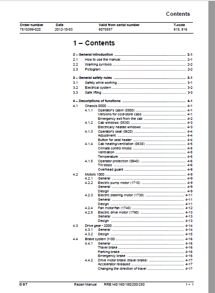
1 – Contents 3
2 – General introduction 19
2 1 How to use the manual 19
2 2 Warning symbols 20
2 3 Pictogram 20
3 – General safety rules 21
3 1 Safety while working 21
3 2 Electrical system 22
3 3 Safe lifting 23
4 – Descriptions of functions 25
4 1 Chassis 0000 25
4 1 1 Operator’s cabin (0500) 25
Versions for cold-store cabs 25
Emergency exit from the cab 26
4 1 2 Cab windows (0530) 27
Electrically heated windows 27
4 1 3 Operator’s seat (0620) 28
Adjustment: 28
Button for seat heater 28
4 1 4 Cab heating/ventilation (0630) 29
Climate control knobs 29
Ventilation 29
Temperature 29
4 1 5 Operator protection (0840) 30
Tilt stops 30
Overhead guard 32
4 2 Motors 1000 33
4 2 1 General 33
4 2 2 Electric pump motor (1710) 33
General 33
Design 33
4 2 3 Electric steering motor (1730) 35
General 35
Design 35
4 2 4 Fan motor/fan (1740) 36
4 2 5 Electric drive motor (1760) 37
General 37
Design 37
4 3 Drive gear – 2000 38
4 3 1 General 38
4 3 2 Design 39
4 4 Brake system 3100 40
4 4 1 General 40
Travel brake 40
Parking brake 40
Emergency brake 40
4 4 2 Drive motor brake (travel brake) 41
Accelerator released 41
Changing the direction of travel 41
4 4 3 Multiple disc brake, support arm (travel brake) 42
General 42
Design 42
4 4 4 Disc brake on the drive motor (parking brake) 43
General 43
Design 43
4 5 Steering system 4000 44
4 5 1 General 44
4 5 2 Design 44
4 5 3 Sensor 45
4 6 Operator compartment 46
4 6 1 Truck control, overview 46
Right-hand control panel, single control 46
Right-hand control panel, multi-control 46
Emergency off switch 47
Steering wheel module 47
Pedals 48
4 6 2 Single-function controls 49
4 6 3 Multi-function controls 50
4 6 4 Central Information Display – CID 51
Navigation 51
LED symbols 54
Information symbols 55
Operator parameter symbols – Overview 56
Blocking symbols – Overview 57
Service functions 59
Calibration functions 61
Automatic calibration of lowering valve 62
Configuration functions 64
Other functions 67
4 6 5 Load Information Display – LID (option) 69
LED symbols 69
Symbols in the display part 70
4 7 sensors and sensors (5800) 71
4 7 1 Inductive sensors 71
4 7 2 Position sensor 71
4 7 3 Magnetic sensor 72
4 8 Operation and connection sequences 73
4 9 Functions 106
4 9 1 General overview 106
Terminology 106
Components 106
4 9 2 MCU – main control unit 107
General 107
Downloading software 107
System communication 107
4 9 3 ACT/ACH transistor regulators 108
General 108
4 9 4 Start-up 108
4 9 5 Shutdown 109
4 9 6 Driving 109
Introduction 109
Acceleration and speed reduction 109
Reversing 110
Brake 110
Travel speed 111
4 9 7 OTP 112
Travel speed reduction – steering angle 112
Travel speed reduction – extension of reach carriage 112
Speed reduction – main lift range 112
Prevention of lifting/lowering of the forks 112
Reduced extension speed 112
4 9 8 Guide 113
Steering position control 113
Steering speed 113
Steering reference 114
Travel speed limitation 114
Compass rose 114
4 9 9 Hydraulic system 115
Definitions 115
Controls 115
Lift 115
Reach movement 116
Lift height limitation 116
Maximum height limitation 116
Auxiliary/Extra functions (option) 117
4 10 Height preselector, description of function 118
4 10 1 Using the height preselector 118
4 10 2 Symbols 118
4 10 3 Buzzer 118
4 10 4 Height preselector levels 119
4 10 5 Level selection 119
4 10 6 Height programming 120
4 10 7 Height preselector and TruckCom 121
4 10 8 Lifting/lowering movement 121
4 10 9 Parameter settings braking at height preselector 122
4 11 Hydraulic system 6000 123
4 11 1 General 123
4 11 2 Tank 123
4 11 3 Filter 123
Return filter 123
Dehumidification filter 123
4 11 4 Hydraulic pump 124
4 11 5 Valve unit 124
Main valve block 124
Second valve block 125
4 11 6 Cylinders 126
Main lift cylinders 126
Free-lift cylinder 126
Cylinders for the reach movement, cabin tilt, sideshift and fork tilt 126
4 11 7 Lift and lowering function 127
Lifting and lowering of free lift 127
Transition from free lift to main lift 127
Lifting and lowering of main lift 127
Reach movement, in and out 127
Simultaneous operation of mast lift and reach movement 128
4 11 8 Extra functions 128
4 11 9 Cabin tilt (RRE Ergo) 128
Hydraulic priority system 128
Cabin tilt (RRE Ergo) during servicing 129
Cabin tilt in the event of hydraulic or electrical power loss 129
4 12 Mast 7000 130
4 12 1 Mast and reach carriage 130
4 13 Lifting devices 131
4 13 1 Fork extensions 131
4 13 2 Telescopic forks 131
4 14 Accessories 9000 133
4 14 1 Radio equipment 133
4 14 2 Extra lighting 133
4 14 3 Extra warning lights/alarm 134
4 14 4 Turn signal lights 134
4 14 5 Movement alarm 135
4 14 6 Positioning/TV equipment 136
4 14 7 Extra electrical equipment 138
4 14 8 Other extra equipment 139
Fork spacers 139
Load rest 140
E-bar 141
Flashlight 142
5 – Parameters 143
5 1 General 143
5 2 Displaying/changing parameters 143
5 3 Operator parameters 144
5 3 1 Overview 144
5 3 2 Connection to logged-in operator 145
5 3 3 Description 146
Parameter 1 – Steering 146
Parameter 2, 3 – Maximum travel speed 148
Parameters 4 and 5 – Acceleration/Retardation 148
Parameter 6 – Cab tilt 148
5 4 General service parameters 149
5 4 1 Overview 149
5 4 2 Description 149
Parameter 101/104 – Service/Logout 149
Parameter 105/106/114/115/117 (Travel alarms 1 and 2) 150
Parameter 107/108 – Battery 152
Parameter 109/110/111/112 – Collision sensor 156
Parameter 113 (shunt value) 157
Parameter 116 (Door on cold store cab) 158
5 4 3 Service parameters, travel functions 159
5 4 4 Overview 159
5 4 5 Description 159
Parameter 201 – Deceleration when reversing 159
Parameter 202/203/204 – Adjusting erroneous, maximum travel speeds 160
Parameter 205/206/207 – Adjusting erroneous, maximum travel speeds 160
Parameter 208 – Creep speed in travel direction control 161
Parameter 209/210 – Reduced maximum travel speed above a certain lift height 161
Parameter 211/212 – Reduced maximum travel speed with a certain reach length 162
Parameter 213 – Permanently reduced maximum travel speed 162
Parameter 214 – Adjusting the maximum travel speed in main lift range 162
5 5 Service parameters, hydraulics 163
5 5 1 Overview 163
5 5 2 Description 166
Parameter 301/302/303/304 – Extra valve function 166
Parameter 305/306/307/308 – Max oil pressure through valve Q8 168
Parameter 313/314/315/316 – Closing time 169
Parameter 317/318/319/320 – Max oil flow through valve Q8 169
Parameter 321/322/323/324 – Max oil flow through valve Q9 170
Parameter 325/326/327/328 – Opening/closing time valve Q8 170
Parameter 329/330/331/332 – Opening/closing time valve Q9 171
Parameter 341/342 – Reducing the lifting/lowering speed 171
Parameter 343 – Reduction of reach speed 172
Parameter 344 – Reduction of fork lowering speed before floor level 172
Parameter 345- Lift/lower sensitivity 172
Parameter 347/348 – Prevent the lifting/lowering of forks 173
Parameter 349 – Fork weight 173
Parameter 350 – Multi-function 174
Parameters 358/359/360 – Deactivation of hydraulic functions 175
Parameters 361/362/363/364/365 /366 – Function related, maximum lift/lowering speeds 176
Parameter 367/368 – Fork limit for deactivating the extension of the fork carriage and for sideshift 177
Parameter 369 through 379 – Height preselector 178
Parameter 380 through 386 – Lift height limitations 180
Parameters 387 through 393 – Configuration of lift height limitations 180
Parameters 395/396/397 – Function-related, maximum lift heights 181
Parameters 398/399 – Operator profile dependent, maximum lift heights 182
5 6 Service parameters, CID 183
5 6 1 Overview 183
5 6 2 Description 184
Parameter 503 – Login method 184
Parameter 504/505/506/507 – Smart Access 184
Parameters 508/509/512/513/514 – CID configuration 189
Parameter 510/511 – Height pre-selector 191
5 7 Service parameters, General Function Unit GFU 192
5 8 General factory parameters 193
5 8 1 Overview 193
5 8 2 Description 194
Parameter 1001 – Truck type 194
Parameter 1002 – (Drive motor) 194
Parameter 1003 – Pedal type 194
Parameter 1004 – Steering servo 195
Parameter 1005 – Pump motor 195
Parameter 1006 – Hydraulic pump 195
Parameter 1007 – Activation of hydraulic levers 196
Parameter 1008 – Mast type 196
Parameter 1009 – Height indication 197
Parameter 1010 – Weight indication 197
5 9 Factory parameters, activation of options 198
Parameter 1115 (Steering angle) 200
Parameter 1116 (Extended mast) 200
Parameter 1117 (Weight of load and fork height) 201
Parameter 1118 (Main lift range) 201
5 10 Factory parameters, calibration 203
6 – Installation 207
6 1 Transporting the truck 207
Method 1 207
Method 2 207
6 2 Initial operation 208
6 2 1 Tool 208
6 2 2 Battery 208
Placing the battery 208
Battery parameters 209
6 2 3 Mast, fitting 209
6 2 4 Parameters on initial operation 209
Load indicator 209
Ergo cabin 210
Cold store cabin 210
6 2 5 Parameters for optional equipment 211
Height measurement (option) 211
Travel speed limitation, height-dependent 211
Travel speed limitation, reach movement dependent 211
Travel speed limitation, parameter-dependent 212
Collision sensor (BT) 212
6 2 6 Test driving 212
7 – Maintenance 215
7 1 Introduction, maintenance 215
7 2 Safety precautions for maintenance work 216
7 3 Checks for cracks 218
7 3 1 Visual inspection 218
7 3 2 Crack detection 219
Crack detection with liquid penetrants 219
Crack detection with magnetic yoke 219
7 4 Periodic maintenance 220
7 4 1 Every 500 B-hours/180 days 220
7 4 2 Every 1000 B-hours/360 days 222
7 4 3 Every 2000 B-hours/720 days 227
7 4 4 Every 3000 B-hours/1080 days 227
7 4 5 Every 5000 B-hours/1800 days 229
7 4 6 Annual status inspection 229
7 5 Maintenance instructions 230
7 5 1 Cleaning and washing 230
High-pressure washers 230
Degreasing agents 230
Cleaning the truck exterior 230
Cleaning the chain 231
Cleaning the motor compartment 231
Electrical components 231
8 – Troubleshooting 233
8 1 Abbreviations used in this section 233
8 2 Truck help functions 233
8 2 1 Error log menu 233
Description 233
Access 233
8 2 2 Error information menu 234
Description 234
Access 234
8 2 3 Diagnostic screens 234
Access 234
State 1 – Voltage from the control console levers 235
State 2 – Digital signals from the truck control to CID 236
State 3 – Voltage from control/sensor to MCU 237
State 4 – Digital input signals to MCU 238
State 5 – Digital output signals from MCU 240
State 6 – PWM output signals from MCU 241
State 7 – FCU (not used) 241
State 8 – FCU (not used) 241
State 9 – GFU (not used) 241
State 10 – GFU (not used) 241
State 11 – Temperature signals 242
State 12 – Voltage levels 242
State 13 – Travel information 243
State 14 – Steering information 244
State 15 – Lift/lowering information 245
Stage 16 – Reach movement information 246
Stage 17 – Hydraulic information 247
State 18 – VNA (not used) 248
State 19 – Pressure sensor for free and main lifts 248
8 3 Initial troubleshooting 249
8 4 Troubleshooting using catch symbol 250
8 5 Troubleshooting using error codes 258
8 5 1 CID, warnings and errors 260
8 5 2 MCU and other warnings and errors 264
8 5 3 Drive system error 274
8 5 4 Hydraulic system error 287
8 5 5 Steering system, warnings and errors 320
8 5 6 GFU, warnings and errors 327
8 6 Troubleshooting without indications 329
8 6 1 Mechanical brake (3000) 329
8 6 2 Steering (4000) 329
8 6 3 Telescopic forks 330
8 6 4 Log on was normal, but one or several functions cannot be used 331
9 – Frame/Chassis 0000 333
9 1 General 333
9 2 Motor hood (0340) 333
9 2 1 Opening the motor compartment 333
RRE 140-RRE 250 333
To open the motor compartment: 333
To close the motor compartment: 333
Replacing the motor hood 334
Adjustment of motor hood 334
9 3 Battery compartment components (0390) 336
9 3 1 Adjusting the battery bed 336
9 4 Operator’s cab (0500) 337
9 4 1 Cab tilting RRE 140 – 250 Ergo 337
9 3 1 Cab windows (0530) 338
Fitting a window 338
9 3 2 Cab door (0550) 340
Disassembly of the door lock 340
Tools required 341
Method 341
Disassembly of the lock device 342
9 4 Operator compartment (0600) 344
9 4 1 Operator’s seat (0620) 344
Disassembling the entire seat 344
Replacing the seat switch 345
Replacing the back rest 346
Replacing the chair seat 347
Replacing the seat heater switch 347
9 4 2 Cab heating/ventilation (0630) 348
Replacing the air filter on the cold store cabin: 348
Removing the fan and heater 349
Replacing the potentiometers 353
9 4 3 Internal fittings (0680) 355
9 4 4 Disassembling/assembling the floor plate, B version 0680 356
9 5 Safety equipment (0800) 358
9 5 1 Checking the overhead guard (0810) 358
9 5 2 Adjusting the tilt stops (0840) 359
10 – Motors 1000 361
10 1 Motor sensors 361
10 1 1 Temperature sensor 361
Retrofitting an external temperature sensor 362
10 1 2 Replacing the motor speed sensor 362
10 2 Pump motor (1710) 363
10 2 1 General 363
The pump motor dismantled 363
10 2 2 Replacing the bearing on the pump motor 364
Dismantling the pump motor 364
Reassembling the pump motor 366
10 3 Steering motor and steering unit (1730) 367
10 3 1 General 367
10 3 2 Layout of the flange holes 367
10 3 3 Removing the steering motor from the truck 368
10 3 4 Fitting the steering motor in the truck 368
10 4 Fan motor/fan (1740) 369
10 4 1 General 369
10 4 2 Replacing the frequency converter cooling fan 369
Standard truck 369
Ergo truck 369
10 4 3 Replacing the motor compartment cooling fan 371
10 5 Drive motor (1760) 372
10 5 1 General 372
The drive motor dismantled 372
10 5 2 Removing the drive motor from the truck 373
10 5 3 Dismantling the drive motor 375
10 5 4 Cleaning 377
10 5 5 Assembling the drive motor 378
10 5 6 Fitting the drive motor in the truck 380
11 – Drive gear 2000 383
11 1 General 383
11 2 Repair- and serviceability 383
11 3 Measures 384
11 3 1 Checking the oil level 384
11 3 2 Oil change 385
Oil refill table 385
11 3 3 Leakage from the bottom cap 386
11 3 4 Replacing the drive gear 387
Special tools 387
Exposing the drive gear 387
Removing a drive motor from the truck 387
Removing a steering motor from the truck 387
Removing the drive gear from the truck 388
Fit the drive gear back in the truck 390
Placing the steering motor in the truck 391
Placing the drive motor in the truck 391
Concluding work 391
12 – Brake and wheel 3000 393
12 1 Travel brake system (3100) 393
12 1 1 Removing the support arm’s multiple disc brake 393
12 1 2 Dismantling the multiple disc brake 393
Inspection 394
Adjusting play 394
Assembling the multiple disc brake 395
12 1 3 Installing the multiple disc brake in the truck 395
12 1 4 Checking the wheel brake’s brake force 396
12 2 Parking brake (3300) 397
12 2 1 General 397
12 2 2 Emergency release of the parking brake 398
12 2 3 Checking the brake force 398
12 2 4 Removing the parking brake from the truck 399
Dismantling and checking for wear 400
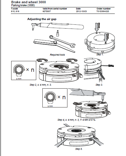
Adjusting the air gap 402
12 2 5 Installing the parking brake in the truck 404
12 3 Drive wheel (3530) 405
12 3 1 General 405
12 3 2 Removing the drive wheel from the truck 405
12 3 3 Installing the drive wheel on the truck 405
12 4 Wheel bolt (3530) 406
General 406
12 4 1 Replacing wheel bolts 406
12 5 Support arm wheel (3550) 407
12 5 1 Removing the support arm wheel from the truck 407
12 5 2 Replacing a wheel bearing – braked wheel (A) 408
12 5 3 Replacing a wheel bearing – unbraked wheel (B) 409
12 5 4 Fitting the support arm wheel to the truck 410
12 5 5 Wheel wear and tear 411
13 – Steering system 4000 413
13 1 Electric steering wheel (4310) 413
13 1 1 General 413
13 1 2 Replacing the pulse transducer on the steering wheel module 413
13 1 3 Removing the operating console from the truck 414
13 1 4 Replacing the wiring harness in the operating console 416
13 1 5 Fitting the operating console in the truck 418
13 2 Steering reference sensor (4350) 419
General 419
13 2 1 Replacing the reference transducer [B17] 419
13 3 Steering bearings (4380) 420
13 3 1 Removing a steering bearing from the drive gear 420
13 3 2 Fitting a steering bearing on the drive gear 420
14 – Electrical system 5000 423
14 1 Battery (5110) 423
14 1 1 Battery recommendation 423
Exide gel batteries (e g Sonnenschein) 423
Hawker Evolution gel batteries 423
14 1 2 Battery installation 424
Replacement/installation of battery 424
Procedure without battery changing table 425
Procedure with battery changing table 425
14 2 LID (5200) 426
14 2 1 Replacing the LID 426
14 2 2 Replacing the LID cold store cab 427
14 3 Replacing pedals (5300) 428
14 3 1 Accelerator and brake pedal 428
14 3 2 Safety pedal 428
14 4 Control console (5510) 429
14 4 1 General 429
14 4 2 Replacement/installation of a control 429
14 4 3 Replacing the multi-function control 430
Replacing the multi-function control’s buttons 430
14 4 4 Removing the control console from the truck 431
14 4 5 Replacing the access card’s circuit board 432
14 4 6 Dismantling the control console 434
Installing an extra push button 436
Replacing the travel direction selector with signal button 436
Replacing the display 437
14 4 7 Assembling the control console 437
14 4 8 Fitting the control console in the truck 438
14 5 Magnetic sensor (5850) 440
General 440
14 5 1 Replacing the magnetic sensor [B47] 440
14 5 2 Reference magnet 441
14 6 Parameter settings 442
14 6 1 Configuration menu 442
Calendar/hour counter menu 442
Parameter menu (PAR) 442
Setting operator parameters 443
14 7 PIN menu 444
14 7 1 Menu for activating a PIN block 445
14 7 2 Menu for programming a PIN (P) 445
14 8 Calibrations 446
14 8 1 Calibrating the hydraulic function control 446
14 8 2 Height measurement/reach movement length calibration 447
Calibrating height measurement (option) 448
14 8 3 Valve calibration 451
Lift valve calibration 451
Lowering valve calibration with height indication 453
Lowering calibration without height indication 455
Reach movement valve calibration 457
Calibration of the Ergo cab 460
14 8 4 Weight calibration 461
Calibrating the weight indicator 461
14 9 Replacing the wiring harness 463
14 10 main computer unit MCU (A5) 464
14 10 1 Installing a new card in the truck 464
14 10 2 Voltage supply 465
14 10 3 Battery negative 465
14 10 4 Internal status monitoring 465
14 10 5 Resetting the battery indicator 465
15 – Hydraulic system 6000 467
15 1 Hydraulic hygiene 467
15 1 1 Washing 467
15 1 2 Packaging 467
15 1 3 Handling 467
15 1 4 Storage 468
15 1 5 Work procedures 468
15 2 Hydraulic unit (6100) 469
15 2 1 Hydraulic tank, emptying 470
15 2 2 Hydraulic system, bleeding 471
15 2 3 Filter 472
Overview 472
Filter replacement (air and oil) 473
15 2 4 Remove the pump motor from the truck 475
15 2 5 Replacing the hydraulic pump 476
15 2 6 Fitting the pump motor in the truck 477
15 3 Main valve (6210) 478
15 3 1 Emergency lowering of forks 478
15 3 2 Replacing the main valve block 480
15 3 3 Replacing the lifting/lowering valves 482
Overview 482
Method 483
15 3 4 Adjusting the maximum opening pressure 486
15 4 Hydraulic connections (6230) 488
15 4 1 Tightening torques for hydraulic connections 488
Tapered coupling with O-ring 488
Tredo sealing 489
Pipe coupling 490
15 4 2 Quick change connector 492
15 5 Hydraulic system, mast (6300) 494
15 5 1 Mast-mounted hose reel (6370) 494
General 494
15 5 2 Fitting the hose reel 494
Spring preloading (turns) 494
15 5 3 Checks after fitting 495
15 6 Main lift cylinder 6610 496
General 496
15 6 1 Overview 497
Cylinder nomenclature 497
Nomenclature for cylinder head 498
Nomenclature for piston 498
15 6 2 Removing the air cylinder from the mast 499
15 6 3 Replacing the hose rupture valve 500
15 6 4 Dismantling the cylinder 502
15 6 5 Dismantling the piston 504
Method 504
15 6 6 Dismantling the cylinder head 504
15 6 7 Fitting the cylinder head seals 506
15 6 8 Fitting the piston seals 508
15 6 9 Assembling the cylinder 510
15 6 10 Assembling cylinder in the mast 512
15 7 Free lift cylinder (6620) 514
General 514
15 7 1 Overview 515
Cylinder nomenclature 515
Nomenclature for cylinder head 516
Nomenclature for piston 516
15 7 2 Removing the free lift cylinder from the truck 517
15 7 3 Replacing the hose rupture valve, free lift cylinder 517
15 7 4 Dismantling the cylinder 518
Tools required 519
Method 519
15 7 5 Dismantling the piston 519
Method 519
15 7 6 Dismantling the cylinder head 520
Method 520
15 7 7 Fitting the cylinder head seals 521
Method 521
15 7 8 Fitting the piston seals 522
Method 523
15 7 9 Assembling the cylinder 524
15 7 10 Assembling the free lift cylinder in the mast 526
15 8 Reach cylinder (6650) 527
15 8 1 General 527
15 8 2 Removing the reach cylinder from the truck 527
15 8 3 Fitting the reach cylinder in the truck 528
15 9 Fork tilt cylinder (6660) 529
15 9 1 General 529
15 9 2 Remove the tilt cylinder from the truck 530
Mast with valve on the fork carriage: 530
Mast without valve on the fork carriage: 532
15 9 3 Fit the tilt cylinder in the truck 534
Mast without valve on the fork carriage: 536
15 10 Cab tilt cylinder (6660) 538
15 10 1 General 538
15 10 2 Overview 538
Cylinder nomenclature 538
Nomenclature for cylinder head 539
Nomenclature for piston 539
15 10 3 Dismantling the cylinder 540
15 10 4 Dismantling the piston rod 542
15 10 5 Dismantling the cylinder head 544
15 10 6 Fitting the cylinder head seals 546
15 10 7 Mounting the piston rod 548
15 10 8 Assembling the cylinder 550
15 11 Sideshift cylinder (6670) 552
15 11 1 General 552
15 11 2 Overview 553
Cylinder nomenclature 553
Nomenclature for cylinder head 554
Nomenclature for piston 554
15 11 3 Dismantling the cylinder from the truck 555
15 11 4 Dismantling the cylinder 556
15 11 5 Dismantling the piston rod 558
15 11 6 Dismantling the cylinder head 560
15 11 7 Fitting the cylinder head seals 562
15 11 8 Mounting the piston rod 564
15 11 9 Assembling the cylinder 566
15 11 10 Refitting the cylinder in the truck 567
16 – Mast/Lift system 7000 569
16 1 Main mast 1 6-2 5 t (7100) 569
16 1 1 Replacing the full mast 569
16 1 2 Removing the mast from the truck 570
16 1 3 Adjusting mast play 573
General 573
Preparations 573
Adjusting lateral play 576
Adjustment of radial play 577
Adjusting the damper parts 577
Adjusting the damper plate 578
Refitting the mast 578
16 1 4 Replacing the mast damper plates 579
16 1 5 Placing the mast on the truck 580
16 2 Main lift chain system (7120) 584
16 2 1 General 584
16 2 2 Checking the chain 584
Noise 584
Surface rust 584
Rusty links 584
Stiff links 585
Bolt rotation 585
Loose bolts 585
Outline wear 586
Stretching 587
Damage 587
Damaged plates 588
Damaged bolts 588
Dirty chain 588
16 2 3 Lubricating the chain 588
16 2 4 Main lift chain system, adjusting the fork-to-floor distance 589
16 3 Reach carriage (7190) 590
16 3 1 Adjusting radial play in the reach carriage 590
16 3 2 Adjusting axial play in the reach carriage 592
16 4 Lifting devices (7400) 593
16 4 1 Forks 593
General 593
Inspection 593
Inspection intervals 593
Surface cracks 593
Difference in height between the fork tips 594
Position lock 594
Readability of the markings 594
Fork blades and back of fork carriage 594
Mounting fixtures on the fork 594
16 4 2 Forks, repairs and testing 595
Repairs 595
Testing the yield point 595
Fork 595
16 5 Fork carriage 596
16 5 1 Checking the fork carriage’s wear strip 596
16 5 2 Lubricating the fork carriage 597
16 6 Fork spread unit 598
16 6 1 Servicing the fork spread unit 598
Replacing bearings 599
Roller replacement 599
16 7 Fork extensions with adjustable fork length 600
16 8 Manual telescopic forks 602
16 8 1 Installation 602
16 8 2 Maintenance 603
16 9 Hydraulic telescopic forks 604
16 9 1 Telescopic forks with separate flow dividers 605
Fitting instructions 606
Initial operation of telescopic forks with separate flow dividers 606
16 9 2 Telescopic forks with integrated flow dividers 607
Fitting instructions 608
Initial operation of telescopic forks with integrated flow dividers 608
16 9 3 Maintenance of telescopic forks 609
16 9 4 Dismantling telescopic forks 610
16 9 5 Assembling telescopic forks 611
17 – Peripherals – 8000 613
17 1 Introduction 613
18 – Extra equipment – 9000 615
18 1 Introduction 615
19 – Appendix “Destruction instructions” 617
19 1 General 617
19 2 Marking of plastics 617
19 2 1 General marking of products and packaging material 617
19 2 2 Marking according to our standard 618
Abbreviations 618
Marking examples 618
19 3 Pressure vessels 619
19 3 1 Gas dampers 619
19 4 Sorting categories 620
20 – Wiring diagram 623
20 1 Components 623
20 2 Component location 633
Figure 1 (Fork carriage) 633
Figure 2 (Chassis wiring harness) 634
Figure 3 (Chassis wiring harness) 635
Figure 4 (Support leg brake) 636
Figure 5 (Pedals) 636
Figure 6 (Motor wiring harness) 637
Figure 7 (Reach carriage wiring harness) 638
Figure 8 (Level/position meter) 639
Figure 9 (seat) 640
Figure 10 (DC/DC) 641
Figure 11 (Driver position wiring harness) 642
Figure 12 (Extra hydraulic function(s)) 643
Figure 13 (Travel alarm) 644
Figure 14 (Roof wiring harness) 645
Figure 15 (Roof) 646
Figure 16 (Sound system) 647
Figure 17 (Forks camera) 648
Figure 18 (Battery harness) 649
Figure 19 (Fuse box) 650
Figure 20 (LID) 651
Figure 21 (Mast wiring harness) 652
Figure 22 (Fork carriage wiring harness) 653
Figure 23 (Reach carriage wiring harness options) 654
Figure 24 (Working light wiring harness) 655
Figure 24 (Extra outlet DC) 656
Figure 25 (T W I S ) 656
Figure 26 (Shock Switch / Impact Manager) 657
Figure 27 (Heated windows CC) 658
Figure 28 (Cabling driver position CC) 659
Figure 29 (Heater CC) 660
Figure 30 (Cab heater wiring harness CC) 661
Figure 31 (Safety switch for door CC) 662
Figure 32 (Cab tilt wiring harness) 662
Figure 33 (Control panel) 663
Figure 34 (Control panel) 664
Figure 35 (Steering arm) 665
Figure 36 (MCU) 666
Figure 37 (Control motor) 667
Figure 38 (Main valve block) 668
20 3 Cable connections and pole bolts 670
20 3 1 ACT/ACH transistor regulators 670
20 3 2 Connections to CID 672
20 3 3 Connections on the MCU 674
20 4 Fuse box A9 676
20 5 Overview 677
20 6 Details up to and including serial no 6206800 682
20 7 Detailed diagram cold-store cab 707
20 8 Details up to and including serial no 6206800 732
20 9 Details cold store cab starting with 6206800 758
21 – Hydraulics schematics 785
21 1 Main valve unit 785
21 1 1 RRE Std 785
21 1 2 RRE Ergo 786
21 2 Hydraulics schematics 787
21 2 1 Schematics designations 787
21 2 2 List of symbols 788
21 2 3 Wiring diagrams RRE/RRE Ergo 789
22 – Tools 795
22 1 AMP connectors 795
22 2 MQS contacts 796
22 3 CPC contacts 798
22 4 Miscellaneous tools 799
23 – Appendix “Service data and grease specifications” 803
23 1 General tightening torques 803
23 1 1 Galvanised non-oiled bolts 803
23 1 2 Untreated oiled bolts 804
23 2 Oil and grease specification 805
24 – Technical data 807
IMAGES PREVIEW OF THE MANUAL:
VIDEO PREVIEW OF THE MANUAL:

PLEASE NOTE:
- This is the same manual used by the dealers to diagnose and troubleshoot your vehicle
- You will be directed to the download page as soon as the purchase is completed. The whole payment and downloading process will take anywhere between 2-5 minutes
- Need any other service / repair / parts manual, please feel free to contact [email protected] . We still have 50,000 manuals unlisted
S.V


