

BT Pallet Truck LWE140 LWE160 LWE180 LWE200 LWE250 Repair Manual 258944-040 – PDF DOWNLOAD
DESCRIPTION:
BT Pallet Truck LWE140 LWE160 LWE180 LWE200 LWE250 Repair Manual 258944-040 – PDF DOWNLOAD
How to use the manual :
The service manual is divided into chapters containing the following
information:
•Functions and parameters – This chapter contains a basic description of the main functions of the truck and the control system parameters.
•Installation and initial operation – This chapter describes the work that needs to be done before the truck is used for the first time.
•Maintenance – This chapter contains a general periodic maintenance schedule and a detailed description of the maintenance to be carried out.
•Troubleshooting – This chapter describes the error codes that appear in the display when the truck completely or partly stops working. The chapter also describes the reason why the errors occur and suggested remedies.
•Step by step – This chapter describes the various parts of the truck, for example the hydraulic system, including what the parts look like and the service activities that need to be carried out. The various descriptions are organised according to BT’s C-code system.
•Appendixes – The appendixes contain:
-instructions for disposal
-information about electrical components and wiring diagrams
-hydraulics diagrams
-list of required tools
-information about general tightening torques
-oil and grease specifications
-Technical data.
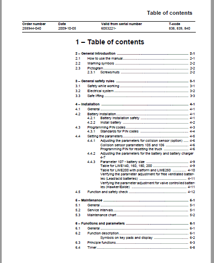
TABLE OF CONTENTS:
BT Pallet Truck LWE140 LWE160 LWE180 LWE200 LWE250 Repair Manual 258944-040 – PDF DOWNLOAD
1 – Table of contents 3
2 – General introduction 9
2 1 How to use the manual 9
2 2 Warning symbols 10
2 3 Pictogram 10
2 3 1 Screws/nuts 10
3 – General safety rules 11
3 1 Safety while working 11
3 2 Electrical system 12
3 3 Safe lifting 13
4 – Installation 15
4 1 General 15
4 2 Battery installation 15
4 2 1 Battery installation safety 15
4 2 2 Install battery 16
4 3 Programming PIN codes 17
4 3 1 Standards for PIN codes 18
4 4 Setting the parameters 19
4 4 1 Adjusting the parameters for collision sensor (option) 20
Collision sensor parameters 105 and 106 20
Programming PIN for resetting the truck 20
4 4 2 Adjusting the parameters for the battery and battery charger 21
4 4 3 Parameter 107 – battery size 23
Table for LWE140, 160, 180, 200 23
Table for LWE200 with platform and LWE250 24
Verifying the parameter adjustment for free ventilated batteries (Lead/acid batteries) 25
Verifying the parameter adjustment for valve controlled batteries (Hawker/Exide) 25
4 5 Function and safety check 26
5 – Maintenance 27
5 1 General 27
5 2 Service intervals 27
5 3 Maintenance chart 28
6 – Functions and parameters 37
6 1 General 37
6 2 Function description 37
Symbols on key pads and display 38
6 3 Principle functions 39
6 4 Timer 44
6 5 Parameters 45
6 5 1 General 45
6 5 2 Show parameters 45
6 5 3 Enter the parameters 46
6 5 4 Driver parameters 47
Factory installed driver parameters 48
6 5 5 Service parameters 49
6 5 6 Factory parameters 52
7 – Troubleshooting 55
7 1 General 55
Software compatibility 55
Emergency travel mode 55
7 2 Troubleshooting methods 56
7 2 1 Troubleshooting general introduction 56
7 2 2 Completed troubleshooting 57
7 3 Error code history 58
7 4 Error code system 59
7 5 Error codes 60
7 6 Troubleshooting diagram 75
7 6 1 The truck cannot be driven 76
7 6 2 The truck can only be driven at reduced speed 77
7 6 3 The truck can be driven but behaves abnormally 78
7 6 4 The truck can be driven but lacks certain functions 78
Software compatibility 78
Matrix for hardware compatibility 79
7 6 5 Faulty hydraulic functions 80
7 7 Built-in test function 83
7 8 Status of digital inputs/outputs 84
7 8 1 Test function “9” – Transistor regulator 84
7 8 2 Test function “10” – Logic card 87
7 8 3 Test function “12” – Expansion unit SEU (optional) 88
7 9 Display test function 89
8 – Chassis 0000 91
8 1 General 91
8 2 Disassemble the drive unit from the fork frame 92
8 3 Removing the platform 93
8 4 Change of damper for castor cradle 95
8 5 Changing the springs and cylinder for the castor cradle 95
9 – Fork frame 0380 97
9 1 Components 97
10 – Electrical drive motor 1700 99
10 1 Components 99
10 2 Remove motor from truck 100
10 3 Fitting the tempreature sensor 101
10 4 Tightening torque Drive motor 102
10 5 Cleaning 103
11 – Drive unit/gear 2550 105
11 1 General 105
11 2 Components 105
11 3 Remove the gear from the truck 106
12 – Brake 3180 107
12 1 Components 107
12 2 Release of brakes 108
13 – Drive wheel 3530 109
13 1 Changing drive wheel 109
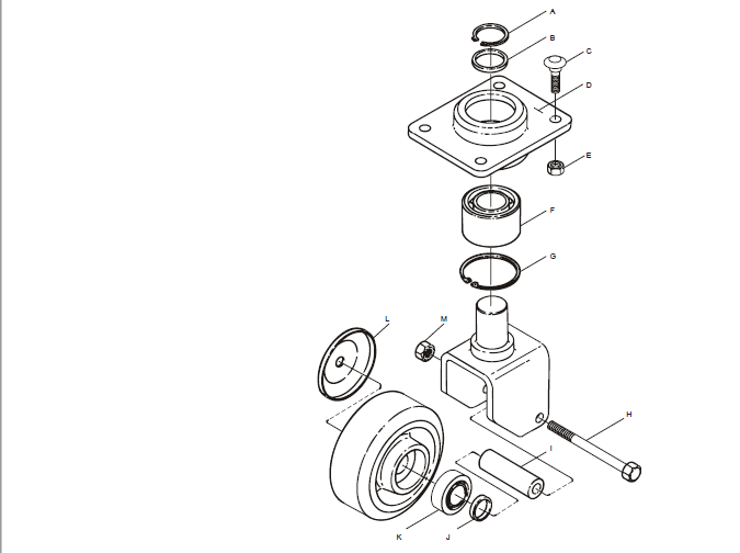
14 – Castor wheel 3540 111
14 1 Components 111
14 2 Castor wheel mounting 112
14 3 Changing castor wheel 113
14 4 Changing castor wheel cradle 113
14 5 Changing springs 113
14 5 1 Removing springs 113
14 5 2 Fitting the spring 113
15 – Fork Wheel 3550 115
15 1 Changing climber wheel 115
15 2 Support arm wheel 3550 116
16 – Tiller arm 4000 117
16 1 Components in tiller arm 117
16 2 Removing tiller arm 118
16 3 Changing gas suspension 118
16 4 Changing the safety sensor 119
16 4 1 Dismantling 119
16 4 2 Assembly 119
16 5 Components in tiller arm handle 120
16 5 1 Removing the tiller arm handle 121
16 5 2 Replacing the logic card 121
16 5 3 Changing signal button/switch 122
16 5 4 Changing raising/lowering button 123
16 5 5 Changing push button 123
16 5 6 Changing the lifting control lever – from front to back 124
16 5 7 Changing a switch for safety reversing 125
17 – Electrical components 127
17 1 Changing wiring harness 127
17 1 1 Changing the wiring harness to the transistor regulator 128
17 2 Replacing the transistor regulator 129
17 3 Lift height limit sensor [B61] 130
17 3 1 Replacing sensor [B61] 130
17 3 2 Adjusting sensor [B61] 131
18 – Hydraulic system 6000 133
18 1 General 133
18 2 Hygiene when working on hydraulics 134
18 2 1 Washing 134
18 2 2 Packaging 134
18 2 3 Handling 134
18 2 4 Storage 135
18 2 5 Carrying out work 135
18 3 Hydraulic system components LWE140, LWE160, LWE180 136
18 4 Hydraulic system components for LWE200 and LWE250 137
18 5 Fitting the tube connection 138
18 6 Hydraulkopplingar 6230 139
18 6 1 Quick change connector 139
Assembling the quick change connector 139
18 7 Adjusting the pressure-limiting valve 140
18 8 Removing the hydraulic unit 141
18 9 Tightening the torque for the hydraulic unit 143
19 – Accessories 145
19 1 Spider expansion unit 145
19 2 TLS – Truck log system 146
19 3 ID unit 146
19 4 Toyota Wireless Information System T W I S 146
19 5 Intergrated battery charger 147
19 5 1 Technical data 147
19 5 2 Battery charging 148
Main charge 148
Uneven charging 148
Charging complete 148
20 – Appendix 149
20 1 General 149
21 – Technical data 151
21 1 LWE140, LWE160, LWE180, LWE200, LWE250 151
22 – General tightening torques 155
22 1 Galvanised, non-oiled bolts 155
22 2 Untreated, oiled bolts 155
23- Tools 157
23 1 MQS connectors 157
23 2 AMP connectors 159
23 2 1 AMP Connectors, 040 series 160
23 3 Molex connectors 160
23 4 Grease guns 161
23 5 Other tools 162
24 – Oil and grease specification 163
24 1 Lubrication schedule 164
25 – Electrical components and electrical diagram 165
25 1 Electrical components 165
25 2 Electrical diagram 169
25 2 1 Index of symbols 169
25 2 2 Overview diagram 170
25 2 3 Electrical diagram 171
26 – Hydraulic diagram 181
27 – Destruction instructions 183
27 1 General 183
27 2 Marking of plastics 183
27 2 1 General marking of products and packaging material 183
27 2 2 Marking according to BT Standard 184
Abbreviations 184
Marking examples 184
27 3 Pressure vessels 185
27 3 1 Gas dampers 185
27 4 Sorting categories 186
IMAGES PREVIEW OF THE MANUAL:
VIDEO PREVIEW OF THE MANUAL:

PLEASE NOTE:
- This is the same manual used by the DEALERSHIPS to SERVICE your vehicle.
- The manual can be all yours – Once payment is complete, you will be taken to the download page from where you can download the manual. All in 2-5 minutes time!!
- Need any other service / repair / parts manual, please feel free to contact us at heydownloadss @gmail.com . We may surprise you with a nice offer
S.V


