

BT SWE140S SWE145 SWE145L SWE160 SWE160L SWE200 SWE200L Repair Manual 7590354 – PDF DOWNLOAD
FILE DETAILS:
BT Pallet Stacker SWE 140S_145(L)_160(L)_200(L) 7590354-040 Repair Manual
Size: 73.5 MB
Fomat: PDF
Language: English
Brand: BT
Type of machine: Forklift – Pallet Stacker
Type of document: Service Manual_Repair Manual
Model:
– BT SWE140S
– BT SWE145
– BT SWE145L
– BT SWE160
– BT SWE160L
– BT SWE200
– BT SWE200L
Part no: 7590354-040
Page of number: 532 pages
Date modifided: 2016
DESCRIPTION:
BT SWE140S SWE145 SWE145L SWE160 SWE160L SWE200 SWE200L Repair Manual 7590354 – PDF DOWNLOAD
General introduction
How to use this manual
How to use this manual
The repair manual is divided into chapters containing the following information:
• General safety rules.
• Operating principle
This chapter provides a basic description of the main functions of the truck and their interdependencies.
• Parameters
This chapter provides a basic description of the truck parameters.
• Installation
This chapter describes the preparatory work that is to be done before the truck is used for the first time
• Maintenance
This chapter provides an overview of periodic maintenance.
• Troubleshooting
The chapter describes the action you should take when the truck is completely or partially out of function. It also
describes the cause of the problem together with suggested remedies.
• C codes
This chapter describes the various truck systems, e.g. the hydraulic system and includes descriptions of system
parts and the necessary service procedures. These descriptions are divided according to the manufacturer’s C
code system.
• Instructions for disposal
This chapter specifies the proper sorting categories for the materials used in the various truck components.
• Wiring diagram
This chapter provides information on electrical components and wiring diagrams.
• Hydraulics schematics
This chapter provides information on hydraulic components and diagrams.
• Tools
This chapter provides a list of the special tools required.
• Service data and grease specifications
This chapter contains information on general tightening torques and specifications for lubricants.
• Technical data.
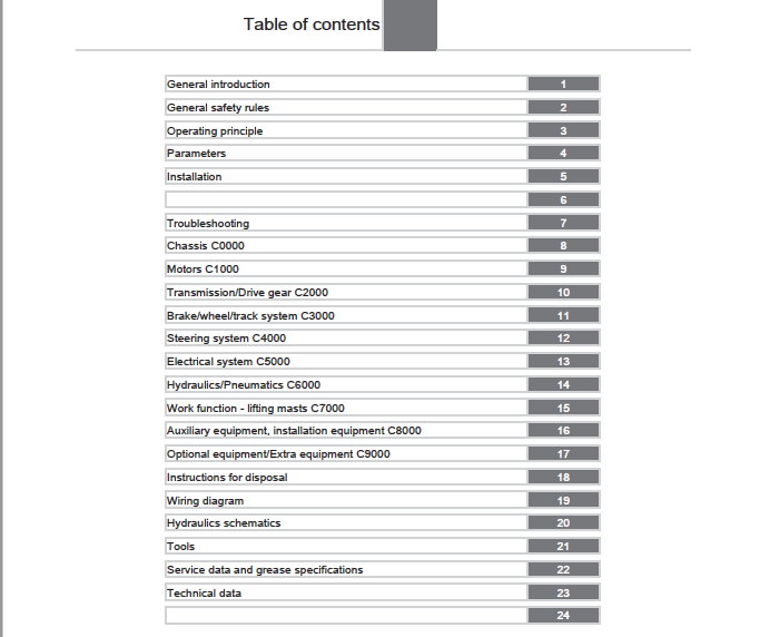
TABLE OF CONTENTS:
BT SWE140S SWE145 SWE145L SWE160 SWE160L SWE200 SWE200L Repair Manual 7590354 – PDF DOWNLOAD
1 General introduction 9
11 How to use this manual 9
12 Warning levels and symbols 9
13 Pictograms 10
2 General safety rules 13
21 Authorised personnel 13
22 Work safety 13
23 Electrical system 13
231 Electrostatic risks 14
232 Battery handling 14
24 Safe lifting 15
25 Truck modifications 15
26 Software 16
27 Hydraulic system 16
3 Operating principle 19
31 Description 19
311 Battery is connected 19
312 Login via keypad 19
313 Login via “ID key” option 19
314 Tiller arm lowered for driving 20
315 Driving in fork direction 20
316 Driving in the drive wheel direction 20
317 Braking in neutral 20
318 Reverse braking 21
319 Mechanical braking 21
3110 Emergency reversal 21
3111 Fork lowering 22
4 Parameters 25
41 Display/change parameters 25
42 Parameters in general 25
43 Parameter list 26
44 Parameter list 26
5 Installation 61
51 Transport 61
511 Transporting the truck 61
512 Transporting the mast 61
52 Lifting the truck 62
521 Lifting the truck 62
522 Lift using a jack 64
53 Commissioning 64
531 Parameters on commissioning 64
5311 Setting parameters 64
5312 Setting collision sensor parameters (option) 64
5313 Setting battery parameters 64
532 Battery 65
5321 Battery installation 65
6291 Placement of signs 69
6292 Placement of signs 71
6293 Placement of signs 73
7 Troubleshooting 79
71 Auxiliary functions 79
711 Towing a defective truck 79
7111 Towing and transporting a defective truck 79
712 Emergency driving mode 79
7121 Emergency driving mode 79
713 Error code history 80
7131 Error code history 80
714 Extended error log 80
7141 Extended error log 80
715 Built-in test function for the tiller arm 80
7151 General 80
7152 Display test 81
7153 Speed control 81
7154 Safety reversing 82
7155 Controls for lifting/lowering 82
7156 Sensilift 83
7157 Keypad 83
72 Initial troubleshooting 84
73 Concluding troubleshooting 84
74 Troubleshooting using error codes 84
741 List of error codes 84
8 Chassis C0000153
81 Overview153
82 Frame, chassis C0300154
821 Inspection covers C0340154
8211 Motor compartment covers154
82111 Overview154
82112 Replacing a service cover154
821121 Removing the service cover154
821122 Fitting the service cover155
82113 Replacing an emblem cover156
821131 Removing the emblem cover156
821132 Fitting the emblem cover156
822 Support arms, stabilizers C0350157
8221 Overview157
8222 Checking the linkage158
8223 Checking the wheel fork flexibility158
8224 Replacing the pressure rod159
82241 Removing a push rod159
82242 Installing a push rod162
8225 Replacing torsion tubes164
82251 Removing torsion tubes164
82252 Installing a torsion tube165
8226 Replacing the roller on the torsion tube166
82261 Removing the roller on the torsion tube166
82262 Fit the roller on the torsion tube168
8227 Replacing a wheel fork169
82271 Removing wheel fork169
82272 Installing a wheel fork170
8228 Replacing a bogie link, fork wheel172
82281 Removing a bogie link, fork wheel172
82282 Fitting a bogie link, fork wheel173
8229 Replacing a bogie link, support arm173
82291 Removing a bogie link, support arm173
82292 Installing a bogie link, support arm174
82210 Replacing the wheel fork bushing174
822101 Removing the wheel fork bushing174
822102 Fitting the wheel fork bushing175
82211 Replacing the support arm bushing175
822111 Removing the support arm bushing175
822112 Installing a support arm bushing176
823 Fork structure (low-lifter) C0380176
8231 Checking the fork lift height limitation176
824 Battery compartment parts C0390177
8241 Overview177
8242 Overview178
8243 Description178
82431 Design178
83 Frame/chassis components C0400178
831 Motor mount/brackets C0450178
8311 Checking the motor mounts178
8312 Drive unit mountings179
83121 Drive unit mounting 6 km/h SWE179
831211 Overview 6 km/h179
831212 Description179
8312121 Technical data179
8312122 Technical data180
8312123 Technical data180
8312124 Technical data180
8312125 Technical data181
8312126 Technical data181
8312127 Technical data181
831213 Replacing the drive unit mounting 6 km/h182
8312131 Removing the drive unit mounting 6 km/h182
8312132 Installing the drive unit mounting 6 km/h183
8313 PowerTrak185
83131 Description185
831311 Design185
83132 Increasing the spring tension187
83133 Releasing the spring tension189
83134 Adjusting tool V08-18302191
83135 Replacing the initial pressure spring192
831351 Removing the initial pressure spring192
831352 Fitting the initial pressure spring193
83136 Replacing the PowerTrak spring194
831361 Removing the PowerTrak spring194
831362 Installing the PowerTrak spring196
83137 Replacing a spacer198
831371 Removing a spacer198
831372 Installing a spacer199
8314 Decompression locking200
83141 Overview200
83142 Description200
831421 Design200
83143 Purging the decompression lock201
83144 Checking the decompression lock203
83145 Replacing the decompression lock203
831451 Removing the decompression lock203
831452 Fitting the decompression lock205
84 Operator compartment, cab C0500207
841 Platform including fixing points C0560207
8411 Replacing the platform207
84111 Removing the platform207
84112 Fitting the platform207
85 Safety equipment C0800208
851 Signs, warnings, labels C0850208
8511 Checking signs and labels208
8512 Placement of signs208
8513 Placement of signs210
8514 Placement of signs212
9 Motors C1000217
91 Electric motors C1700217
911 Electric pump motor C1710217
9111 Overview217
9112 Replacing the pump motor217
91121 Removing a pump motor217
91122 Installing a pump motor218
912 Electric fan motor/fan C1740219
9121 Overview219
9122 Description219
91221 Design219
9123 Replacing the motor control fan220
91231 Removing a motor control fan220
91232 Installing a motor control fan221
913 Electric drive motor C1760222
9131 Overview 18, 25 kW222
9132 Description222
91321 Design222
9133 Check the rotational speed sensor fitting223
9134 Checking the electrical connections223
9135 Checking the drive motor223
9136 Listen for any abnormal noise in the drive motor bearings223
9137 Check the drive motor fitting (18 and 25 kW)223
9138 Checking the rotational speed sensor223
9139 Replacing the drive motor223
91391 Removing the drive motor [M1]223
91392 Installing the drive motor [M1]227
91310 Replacing the temperature sensor230
913101 Installing the temperature sensor230
91311 Replacing the rotational speed sensor231
913111 Removing a rotational speed sensor231
913112 Installing a rotational speed sensor233
91312 Replacing the toothed wheel234
913121 Removing a toothed wheel234
913122 Installing a toothed wheel235
10 Transmission/Drive gear C2000239
101 Drive unit, final gear C2500239
1011 Drive unit/gear C2550 239
10111 Overview239
10112 Description 239
101121 Design239
101122 Technical data240
10113 Check the drive gear’s attachment 240
10114 Checking for leaks in the drive gear240
10115 Checking for noise in the drive gear240
10116 Replacing the drive gear 240
101161 Removing the drive gear240
101162 Installing the drive gear243
10117 Replacing the wheel hub seal 244
101171 Removing the wheel hub seal244
101172 Installing the wheel hub seal246
10118 Drive gear oil change246
101181 Empty the drive gear oil247
101182 Filling oil in the drive gear248
10119 Replacing the drive gear steering bearing 248
101191 Removing the drive gear steering bearing248
101192 Installing the drive gear steering bearing249
101110 Stud replacement 250
1011101 Removing a stud250
1011102 Installing a stud251
11 Brake/wheel/track system C3000255
111 Travel brake system C3100255
1111 Description255
11111 Brake types255
111111 Travel brake255
111112 Emergency brake255
111113 Parking brake255
112 Parking brake details C3300256
1121 Electrical parking brake, magnet brake C3370256
11211 Overview256
11212 Description257
112121 Technical data257
11213 Cleaning the parking brake257
11214 Adjusting the parking brake gap258
11215 Adjusting the parking brake gap258
11216 Tighten the parking brake mounting bolts259
11217 Emergency release of the parking brake259
11218 Checking the parking brake260
11219 Replacing the brake hub260
112191 Disassembling the brake hub260
112192 Installing a brake hub261
112110 Replacing the friction disc261
1121101 Removing the friction disc261
1121102 Fitting the friction disc262
112111 Replacing the parking brake263
1121111 Removing the parking brake263
1121112 Fitting the parking brake264
113 Wheels C3500266
1131 Drive wheel C3530266
11311 Overview266
11312 Description267
113121 Wheel wear267
11313 Measuring the drive wheel tread267
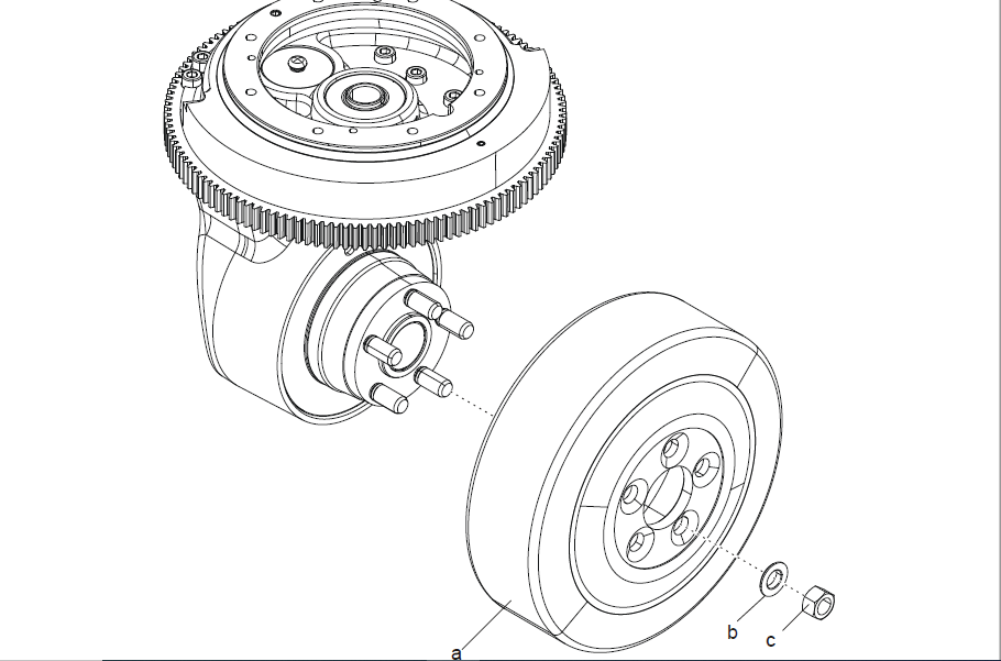
11314 Replacing the drive wheel267
113141 Removing the drive wheel267
113142 Fitting the drive wheel269
1132 Support arm wheels/castor wheels C3540270
11321 Overview270
11322 Description271
113221 Wheel wear271
11323 Cleaning castor wheels271
11324 Measuring the castor wheel tread271
11325 Measuring the castor wheel tread272
11326 Measuring the castor wheel tread272
11327 Measuring the castor wheel tread272
11328 Checking the castor wheels272
11329 Replacing the castor wheel272
113291 Removing the castor272
113292 Removing the castor273
113293 Installing a castor wheel274
113294 Installing a castor wheel275
113210 Replacing the castor wheel assembly276
1132101 Removing the castor wheel assembly276
1132102 Installing the castor wheel assembly277
1133 Fork wheels/support arm wheels C3550278
11331 Overview278
11332 Description278
113321 Wheel wear278
11333 Cleaning the fork wheels279
11334 Measuring the fork wheel tread279
11335 Checking the fork wheel mounting279
11336 Checking the fork wheel bushings279
11337 Replacing a single wheel279
113371 Removing single wheels279
113372 Single wheel installation280
11338 Replacing bogie wheels281
113381 Removing bogie wheels281
113382 Removing bogie wheels283
113383 Fitting the bogie wheel285
113384 Fitting the bogie wheel286
11339 Replacing a bogie link288
113391 Removing a bogie link288
113392 Removing a bogie link288
113393 Installing a bogie link289
113394 Installing a bogie link289
12 Steering system C4000293
121 Mechanical steering system C4100293
1211 Steering arm/wheel/lever C4110293
12111 Overview tiller arm293
12112 Operating panel294
121121 Overview operating panel294
121122 Controls295
1211221 Replacing the signal button/switch295
12112211 Removing the signal button/switch295
12112212 Fitting the signal button/switch296
1211222 Replacing the lift/lower button298
12112221 Removing the lift/lower button298
12112222 Fitting the lift/lower button299
12112223 Checking the hydraulic functions300
1211223 Replacing the stomach button300
12112231 Removing the stomach button300
12112232 Installing a stomach button301
12112233 Checking the stomach button302
1211224 Replacing the sensilift302
12112241 Removing the sensilift302
12112242 Installing sensilift303
1211225 Changing the position of the controls – support arm lift/fork lift303
1211226 Replacing the keypad304
12112261 Removing the keypad304
12112262 Installing a keypad304
121123 Replacing the operating panel304
1211231 Removing the operating panel304
1211232 Installing an operating panel305
1211233 Checking the speed control307
121124 Replacing the logic card307
1211241 Removing the logic card307
1211242 Installing a logic card308
1211243 Logic card [A5]310
12113 Tiller arm handle310
121131 Replacing the handle to the tiller arm310
1211311 Removing the tiller arm handle310
1211312 Fitting the handle to the tiller arm311
12114 Tiller arm312
121141 Replacing the tiller arm312
1211411 Removing the tiller arm312
1211412 Fitting tiller arm314
121142 Replacing the tiller arm assembly316
1211421 Removing the tiller arm assembly316
1211422 Fitting the tiller arm assembly317
121143 Checking the brake microswitches318
121144 Checking the play and the return travel318
121145 Replacing the tiller arm cover319
1211451 Removing the tiller arm cover319
1211452 Fitting the tiller arm cover319
121146 Replacing the tiller arm housing320
1211461 Removing the tiller arm housing320
1211462 Fitting the tiller arm housing321
12115 Steering yoke322
121151 Overview steering servo322
121152 Replacing the steering yoke322
1211521 Removing the steering yoke322
1211522 Fitting the steering yoke324
121153 Replacing the steering yoke cover325
1211531 Removing the steering yoke cover325
1211532 Fitting the steering yoke cover326
121154 Changing the tiller arm damper326
1211541 Removing the tiller arm damper326
1211542 Installing the tiller arm damper328
121155 Replacing the safety switch329
1211551 Removing the safety switch [B60]329
1211552 Installing the safety switch [B60]330
12116 Tiller arm wiring harness331
121161 Replacing the tiller arm wiring harness331
1211611 Removing the tiller arm wiring harness331
1211612 Fitting the tiller arm wiring harness332
122 Electric steering system C4300333
1221 Steering angle sensor C4350333
12211 Replacing the steering angle sensor mech 333
122111 Removing the steering angle sensor mech333
122112 Installing the steering angle sensor mech335
13 Electrical system C5000341
131 Description341
1311 General341
1312 Truck firmware applications341
132 Software update341
133 Programming tools341
1331 TruckCom341
13311 Connect the CAN interface to the truck341
1332 Software342
13321 Software update342
134 General electric equipment C5100342
1341 Battery C5110342
13411 Cleaning the battery342
13412 Checking the connections342
13413 Checking the battery cables343
13414 Checking the battery343
13415 Checking cell and terminal protectors343
13416 Checking the level of the electrolyte343
13417 Checking the electrolyte density344
13418 Checking the battery parameters344
13419 Checking the battery voltage344
134110 Resetting/restarting the battery344
134111 Charging the battery345
134112 Replacing a battery using a lifting device346
1341121 Removing a battery using a lifting device346
1341122 Installing a battery using a lifting device346
134113 Replacing a battery using a battery changing table349
1341131 Removing a battery using a battery changing table349
1341132 Installing a battery using a battery changing table349
1342 General alarm signals (audible/visual) C5160352
13421 Horn352
134211 Overview352
134212 Checking the horn function352
1343 Battery charger (built-in) C5170352
13431 Checking the battery charger cables352
13432 Checking the battery charger parameters352
1344 Battery cut out switch, main contactor C5190353
13441 Main contactor353
134411 Replacing the main contactor353
1344111 Removing the main contactor353
1344112 Fitting the main contactor356
135 Instrument panel, display C5200358
1351 Menu358
13511 Menus358
13512 Menu navigation358
13513 Menu list359
13514 Menu information359
13515 Show hour meter values359
13516 Show error codes360
13517 Show part numbers for software/hardware360
13518 Built-in test ICH360
13519 Show collisions361
135110 Show/change parameters361
135111 Emergency driving mode361
135112 Calibration361
135113 Show/change PIN code361
135114 PIN codes362
1351141 General362
1351142 PIN code for resetting the truck362
1351143 Programming PIN codes362
1351144 PIN code defaults364
1352 Hour counter, tachograph C5290364
13521 Checking error log and operating hours364
136 Control system travel function C5300364
1361 Direction selector/speed regulator364
1362 Pressure equalization365
1363 Weighing system365
1364 Display365
1365 Symbols on keypad and display365
1366 Option buttons365
1367 Signal buttons365
1368 Lifting and lowering control365
1369 Hour meter366
13610 Battery indicator366
13611 Safety reversing366
13612 Travel function wiring/fuse C5390366
136121 Description366
1361211 Fuses366
137 Power system travel function C5400367
1371 Overview367
1372 Transistor panel C5460367
13721 Description367
137211 General367
13722 Checking the contactors368
13723 Checking the cable connections368
13724 Checking the electric panel mounting368
13725 Cleaning the electric panel heatsink368
13726 Replacing the motor control panel368
137261 Removing the motor control panel368
137262 Installing the motor control panel369
138 Control system, working function C5500370
1381 Work function harnesses/fuse C5590370
13811 Checking the wiring harnesses370
139 Protective sensors, position sensors C5800370
1391 Description370
13911 Inductive sensors370
139111 Position sensors370
139112 Steering reference sensor371
13912 Pressure sensor372
13913 Pulse transducer372
1392 Safety probes/sensors C5830373
13921 Emergency switch off373
139211 Description373
1392111 Task and function373
139212 Checking the emergency switch function373
1310 Calibrations373
13101 Steering angle calibration373
13102 Hydraulic valve calibration374
131021 Proportional valve calibration374
131022 Tilt angle calibration375
13103 Pressure sensor calibration375
131031 Weight measuring calibration375
131032 Overload calibration376
14 Hydraulics/Pneumatics C6000379
141 Overview379
142 Description379
1421 Hydraulic hygiene379
14211 Washing379
14212 Packaging380
14213 Handling380
14214 Storage380
14215 Work procedures380
14216 General rules380
14217 Measures381
1422 Design382
143 Quick change connectors382
1431 Overview quick change connectors382
1432 Removing quick change connectors (female)382
1433 Installing quick change connector (female)383
1434 Removing a quick change connector (male)384
1435 Installing a quick change connector (male)385
144 Hydraulic unit C6100386
1441 Hydraulic unit386
1442 Description386
14421 Pressure limiting valve386
1443 Hydraulic oil tank C6110387
14431 Tank387
14432 Description387
144321 Design387
14433 Cleaning the tank387
14434 Checking the tank387
14435 Oil change387
144351 Draining oil387
144352 Topping up with oil388
14436 Replacing the tank389
144361 Removing the tank389
144362 Fitting the tank389
1444 Filter, filter housing C6130389
14441 Cleaning the suction filter389
14442 Oil filter replacement390
144421 Removing oil filter390
144422 Installing the oil filter390
14443 Replacing the suction filter391
144431 Removing suction filter391
144432 Installing the suction filter392
1445 Hydraulic pump C6140393
14451 Hydraulic pump393
14452 Description393
144521 Design393
1446 Pressure/flow control valve C6170393
14461 Description393
144611 Checking the pressure limiting valve393
14462 Replacing the flow control valve394
144621 Removing the flow control valve394
144622 Fitting the flow control valve395
14463 Replacing the pressure limiting valve395
144631 Removing the pressure limiting valve395
144632 Fitting the pressure limiting valve396
1447 Replacing the hydraulic unit396
14471 Removing the hydraulic unit396
14472 Fitting the hydraulic unit397
1448 Replacing the valve coil398
14481 Removing the valve coil398
14482 Fitting the valve coil399
1449 Replacing the pressure sensor399
14491 Removing the pressure sensor399
14492 Fitting the pressure sensor400
145 Hydraulic system, fitted on the mast C6300400
1451 Mast hydraulic conduits C6320400
14511 Checks for leaks from hydraulic conduits and connections, hydraulic unit400
14512 Checks for leaks from hydraulic conduits and connections, mast400
146 Hydraulic cylinder C6600401
1461 Main lift cylinders C6610401
14611 Checking for leaks in the lift cylinder401
14612 Replacing the main lift cylinders401
146121 Removing the lift cylinder401
146122 Fitting the lift cylinder403
1462 Support arm/initial lift cylinder C6630404
14621 Replacing the main initial lift cylinder404
146211 Removing the initial lift cylinder404
146212 Installing the initial lift cylinder406
1463 PowerTrak cylinder C6680407
14631 Replacing the PowerTrak cylinder407
146311 Removing the PowerTrak cylinder407
146312 Installing the PowerTrak cylinder408
15 Work function – lifting masts C7000413
151 Description413
1511 Ordering a replacement mast413
152 Chain system, general413
1521 General413
1522 Adjusting the chain413
1523 Lubrication413
1524 Checking the chains414
15241 Noise414
15242 Surface rust414
15243 Rusty links414
15244 Stiff links414
15245 Bolt rotation414
15246 Loose bolts415
15247 Outline wear415
15248 Chain gauge416
15249 Stretching416
152410 Damaged plates417
152411 Damaged bolts417
152412 Other damage417
152413 Dirty chain417
153 Checking the chains418
154 Lubricating the chains418
155 Checking the split pins419
156 Check-tighten the locking nuts419
157 Main mast C7100419
1571 Check the position of the mast guide419
1572 Check for cracks/damages to the mast420
1573 Lubrication of the mast roller guides 420
1574 Measuring the mast inclination420
1575 Adjusting the mast inclination421
1576 Replacing the roller422
15761 Installing a roller422
1577 Replacement of the mast422
15771 Disassembling the mast422
15772 Removing a roller424
15773 Assembling the mast425
15774 Installing a roller427
1578 Main mast fork carriage C7130427
15781 Replacing the idler roller427
157811 Removing a roller427
1579 Initial lift of frame/mast C7160428
15791 Replacing the main initial lift cylinder428
157911 Disassembling the fork carriage428
157912 Installing a fork carriage429
15710 Main mast suspension C7190430
157101 Mast mount430
1571011 Tightening the upper mast fixing points430
1571012 Check-tighten the locking nuts431
1571013 Tightening the lower mast fixing points431
158 Lifting/carrying/clamping devices C7400431
1581 Fork carriage unit/with integrated sideshift/fork spread C7420431
15811 Checking the fork carriage431
15812 Check the play of the fork carriage431
15813 Lubricating the beams432
15814 Measuring the fork-to-floor distance432
15815 Replacing the fork carriage432
158151 Disassembling the fork carriage432
158152 Installing a fork carriage434
16 Auxiliary equipment, installation equipment C8000439
17 Optional equipment/Extra equipment C9000443
171 Overview443
172 Extra electrical equipment C9400444
1721 Extra power socket444
17211 Overview444
17212 Description444
172121 DC/DC converter444
1722 Truck log equipment, code lock C9420445
17221 Overview445
17222 I_Site445
172221 Description445
1722211 I_Site445
17223 Impact Manager446
172231 Description446
1722311 Collision sensor446
172232 Checking the reference sensor parameters446
172233 Checking DHU/TWIS [K110]446
173 Other extra equipment C9500446
1731 Fire extinguisher446
17311 Description446
173111 Fire extinguisher446
1732 Horizontal E-bar447
17321 Description447
173211 E-bar447
17322 Checking the E-bar lock448
1733 Spider expansion unit448
17331 Description448
173311 Spider expansion unit448
18 Instructions for disposal453
181 General453
182 Marking of plastics453
1821 General marking of products and packaging453
1822 Marking according to the manufacturer’s standards453
18221 Abbreviations453
18222 Marking examples454
183 Pressure vessels454
1831 Gas struts454
184 Sorting categories455
19 Wiring diagram459
191 Colour code table459
192 Diagram459
1921 Component list459
1922 Component placement463
1923 Detailed diagrams477
20 Hydraulics schematics505
201 Component list505
202 Component location506
2021 Picture 1506
2022 Picture 2507
2023 Picture 3508
2024 Picture 4508
203 Valve unit510
2031 Valve unit 1-function510
2032 Valve unit 2-functions511
204 Diagram512
205 Diagram513
206 Diagram514
21 Tools517
211 Tools for electric connectors517
2111 AMP connectors517
2112 MQS connectors517
2113 CPC connectors518
2114 AMP Seal connectors519
212 Special tools519
22 Service data and grease specifications523
221 General tightening torques523
2211 Galvanised, non-oiled screws523
2212 Untreated, oiled screws523
222 Lubricants specification524
23 Technical data527
24 529
IMAGES PREVIEW OF THE MANUAL:
VIDEO PREVIEW OF THE MANUAL:

PLEASE NOTE:
- This is the SAME exact manual used by your dealers to fix your vehicle.
- The same can be yours in the next 2-3 mins as you will be directed to the download page immediately after paying for the manual.
- Any queries / doubts regarding your purchase, please feel free to contact [email protected]
S.V


