

BT SPE125 125L 135S 160 160L 200D 200 200L Service Manual 230076-040 – PDF DOWNLOAD
DESCRIPTION:
BT SPE125 125L 135S 160 160L 200D 200 200L Service Manual 230076-040 – PDF DOWNLOAD
Valid from serial number: 924454-
Order number: 230076-040
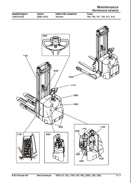
Maintenance:
- To assure maximum safety and minimum downtime, all items in the service programme should be covered. The service intervals are only guidelines and need not be strictly followed.
- The operator of the truck should adapt these to local requirements, however, it is important that the minimum requirements as stated by BT are observed. The service intervals are based on truck operating hours and can be adapted to most common 8-hour shifts.
When calculating the service intervals, the following operating hours have been used:
Day time:08.00-17.00 (20 hours/week)
Double shift:06.00-14.00, 14.00-22.00 (40 hours/week)
Triple shift:06.00-14.00, 14.00-22.00, 22.00-06.00
(60 hours/week)
Safety rules during maintenance work :
Only technicians who have received the necessary training for service and repairs of this truck type may carry out service and repair work.
•Do not perform any repair work on the truck unless properly trained and possessing the necessary skills to perform such work.
•Keep the service site clean. Oil and water on the floor could make it slippery.
•Never wear loose items and jewellery when working on the truck.
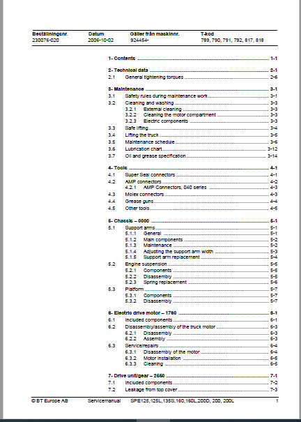
TABLE OF CONTENTS:
BT SPE125 125L 135S 160 160L 200D 200 200L Service Manual 230076-040 – PDF DOWNLOAD
2- Technical data 9
2 1 General tightening torques 15
3- Maintenance 17
3 1 Safety rules during maintenance work 17
3 2 Cleaning and washing 19
3 2 1 External cleaning 19
3 2 2 Cleaning the motor compartment 19
3 2 3 Electric components 19
3 3 Safe lifting 20
3 4 Lifting the truck 21
3 5 Maintenance schedule 22
3 6 Lubrication chart 28
3 7 Oil and grease specification 30
4- Tools 31
4 1 Super Seal connectors 31
4 2 AMP connectors 32
4 2 1 AMP Connectors, 040 series 33
4 3 Molex connectors 33
4 4 Grease guns 34
4 5 Other tools 35
5- Chassis – 0000 37
5 1 Support arms 37
5 1 1 General 37
5 1 2 Main components 38
5 1 3 Maintenance 38
5 1 4 Adjusting the support arm width 39
5 1 5 Support arm replacement 40
5 2 Engine suspension 41
5 2 1 Components 41
5 2 2 Disassembly 41
5 2 3 Spring replacement 42
5 3 Platform 43
5 3 1 Components 43
5 3 2 Disassembly 43
6- Electric drive motor – 1760 45
6 1 Included components 45
6 2 Disassembly/assembly of the truck motor 47
6 2 1 Disassembly 47
6 2 2 Assembly 47
6 3 Service/repairs 48
6 3 1 Disassembly of the motor 48
6 3 2 Motor installation 49
6 3 3 Cleaning 49
7- Drive unit/gear – 2550 51
7 1 Included components 52
7 2 Leakage from top cover 53
7 3 Replacing the drive axle jointing ring 53
7 3 1 Disassembly 54
7 3 2 Assembly 54
8- Electromagnetic brake – 3370 55
8 1 Main components of the brake 55
8 2 Maintenance 56
8 2 1 Basic adjustment of the play 56
8 2 2 Brake disc replacement 57
8- Support/Castor Wheels – 3540 59
8 1 Tightening torque 59
9- Electrical steering system – 4300 61
9 1 Electrical steering servo 61
9 1 1 General 61
9 2 Steering servo components 62
9 3 Adjustment 63
9 3 1 Reference sensor 63
9 3 2 Calibration 63
Parameter 36 63
Parameter 37 63
10- Electrical systems – 5000 65
10 1 General 65
10 1 1 Part numbers 65
10 1 2 Nomenclature 65
10 2 Electrical equipment overview 67
10 2 1 Component placement 67
10 2 2 Component list 69
10 3 Electrical wiring diagram 73
10 3 1 Symbol list 73
10 3 2 Overview 74
10 3 3 Detailed wiring diagram 75
10 4 Functional description 91
10 4 1 Principle of operation 92
10 4 2 Description of steering system 98
10 4 3 Spider expansion unit (SEU) 98
10 4 4 Speed limitation 100
10 4 5 Hour meter and battery condition 101
10 4 6 TLS – Truck log system (optional) 102
General 102
Registration 102
Logging in/out SD16 102
Logging in/out S16 102
Collision sensor 103
Settings 103
10 4 7 ID unit (optional) 104
10 4 8 Cooling fan (SPE200D) 104
10 4 9 Insert (SPE200D) 105
10 5 Parameters 106
10 5 1 General 106
10 5 2 Viewing parameters -CAN key not connected 106
10 5 3 Viewing parameters – CAN key connected 107
10 5 4 Setting Driver parameters 108
10 5 5 Setting Service parameters 108
10 5 6 Summary of driver parameters 109
10 5 7 Description of driver parameters 110
# 2 – Maximum speed, high range 110
# 3 – Maximum acceleration 110
# 4 – Neutral braking effect 110
# 6 – Maximum speed, low range 110
# 7 – Maximum speed, “Turtle” mode 110
10 5 8 Summary of service parameters 111
10 5 9 Description of service parameters 113
# 10 – PIN code 113
To enter a new PIN-code: 113
To remove an existing PIN-code: 114
# 14 – Creep speed 114
#15 – Non-configurable options 114
Setting Non-configurable options 114
#16 – Configurable option #1 115
#17 – Configurable option #2 115
#18 – Configurable option #3 115
#19 – Configurable option #4 115
# 20 – Hour meter selection 116
# 21 – Battery size 117
# 22 – Maximum fork lowering speed 117
# 23 – Fork lower stop ramp 117
# 25 – Service interval 117
# 35 – Log off 118
# 36 – Calibrate 118
# 37 – Steering offset 121
# 38 – Steer servo activated 121
# # 39 – Log-in method & operator parameter access 121
Extended keypad – General 122
Extended keypad – Programming 122
10 5 10 Configurable “Option” Parameters 124
General 124
Parameter #16 to #19 Configurable options 125
10 6 Diagnostic and troubleshooting 135
10 6 1 General 135
10 6 2 Fault code history 136
10 6 3 List of fault codes 136
10 6 4 Transistor regulator 144
General 144
Transistor regulator errors 145
Resetting errors 146
Safety 146
10 6 5 Built-in Test Function 146
Digital inputs/outputs test mode 148
10 6 6 Display test mode 150
10 7 Technical specifications – Curtis 1243 151
11- Hydraulic system – 6000 153
11 1 Hydraulic diagram 153
11 1 1 With height-adjustable support arms 153
11 1 2 Without height-adjustable support arms 154
11 2 Main Components 155
11 3 Description 156
11 3 1 Lifting system 156
11 3 2 The PowerTrak system 156
11 3 3 Working pressure 157
11 3 4 Overflow valve 157
11 3 5 Pressure sensor 157
12- Lift mast – 7000 159
12 1 Mast incline 159
12 2 Main lift chain system 160
12 2 1 Checking the chain setting 160
12 2 2 Chain inspection 160
Noise 160
Surface rust 160
Rusty links 160
Stiff links 160
Bolt rotation 161
Loose bolts 161
Outline wear 161
Stretching 162
Damage 163
Damaged discs 163
Damaged bolts 163
Dirty chain 163
12 2 3 Cleaning 163
12 2 4 Lubrication 164
14- Destruction instructions 167
14 1 General 167
14 2 Procedure 167
14 3 Abbreviations 168
14 4 Sorting 168
14 5 Chassis (0300) 169
14 5 1 Dismantling 169
14 5 2 Material handling 169
14 6 Hoods, covers (0340) 170
14 6 1 Dismantling 170
14 6 2 Material handling 170
14 7 Fork structure (low-lifter) (0380) 171
14 7 1 Dismantling 171
14 7 2 Material handling 171
14 8 Travel platform including mount (0560) 172
14 8 1 Dismantling 172
14 8 2 Material handling 172
14 9 Overhead guard (option) (0810) 173
14 9 1 Dismantling 173
14 9 2 Material handling 173
14 10 Operator protective device (0840) 174
14 10 1 Dismantling 174
14 10 2 Material handling 174
14 11 Electric pump motor (1710) 175
14 11 1 Dismantling 175
14 11 2 Material handling 175
14 12 Electric travel drive motor (1760) 176
14 12 1 Dismantling 176
14 12 2 Material handling 176
14 13 Drive unit/gear (2550) 177
14 13 1 Dismantling 177
14 13 2 Material handling 177
14 14 Wheels (3500) 178
14 14 1 Dismantling 178
14 14 2 Material handling 178
14 15 Steering arm (4110) 179
14 15 1 Dismantling 179
14 15 2 Material handling 179
14 16 Steering arm (4110) 180
14 16 1 Dismantling 180
14 16 2 Material handling 180
14 17 General electric equipment (5100) 181
14 17 1 Dismantling 181
14 17 2 Material handling 181
14 18 Cabling (5590) 182
14 18 1 Dismantling 182
14 18 2 Material handling 182
14 19 Steering and protective electronics (5700) 183
14 19 1 Dismantling 183
14 19 2 Material handling 183
14 20 Lift/lowering sensor (5820) and safety sensor (5830) 184
14 20 1 Dismantling 184
14 20 2 Material handling 184
14 21 Hydraulic unit (6100) 185
14 21 1 Dismantling 185
14 21 2 Material handling 185
14 22 Main mast (7100) 186
14 22 1 Dismantling 186
14 22 2 Material handling 186
14 23 Chassis-mounted hydraulic oil lines (6230) (and main lift cylinder (6610)) 187
14 23 1 Dismantling 187
14 23 2 Material handling 187
14 24 Battery charger connector (9380) 188
14 24 1 Dismantling 188
14 24 2 Material handling 188
IMAGES PREVIEW OF THE MANUAL:
VIDEO PREVIEW OF THE MANUAL:

PLEASE NOTE:
- This is the same manual used by the dealers to diagnose and troubleshoot your vehicle
- You will be directed to the download page as soon as the purchase is completed. The whole payment and downloading process will take anywhere between 2-5 minutes
- Need any other service / repair / parts manual, please feel free to contact [email protected] . We still have 50,000 manuals unlisted
S.V


