

Sumitomo SH330-5B, SH350-5B Hydraulic Excavator Shop Manual
FILE DETAILS:
LANGUAGE:ENGLISH
PAGES:280
DOWNLOADABLE:YES
FILE TYPE:PDF
VIDEO PREVIEW OF THE MANUAL:

IMAGES PREVIEW OF THE MANUAL:
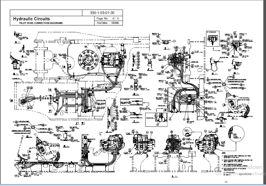
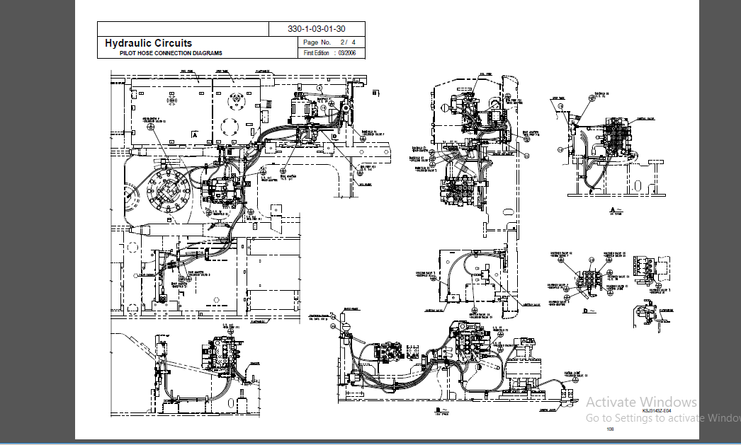
TABLE OF CONTENTS:
Sumitomo SH330-5B, SH350-5B Hydraulic Excavator Shop Manual
Specifications
Specifications (SH330-3B) 330-1-01-00-61 1/6 1
Complete Machine Dimensions300-1-01-01-19
Standard Arm (325 m) 1/3 7
Short Arm (263 m) 2/3 8
Long Arm (404 m) 3/3 9
Work Range300-1-01-02-19
Standard Arm (325 m) 1/3 10
Short Arm (263 m) 2/3 11
Long Arm (404 m) 3/3 12
Specifications (SH330LC-3B)330-1-01-00-62 1/6 13
Complete Machine Dimensions300-1-01-01-20
LC Standard Arm (325 m) 1/3 19
LC Short Arm (263 m) 2/3 20
LC Long Arm (404 m) 3/3 21
Work Range300-1-01-02-20
LC Standard Arm (325 m) 1/3 22
LC Short Arm (263 m) 2/3 23
LC Long Arm (404 m) 3/3 24
Specifications (SH350HD-3B) 350-1-01-00-63 1/6 25
Complete Machine Dimensions350-1-01-01-21
HD Standard Arm (325 m) 1/2 31
HD Short Arm (263 m) 2/2 32
Work Range350-1-01-02-21
HD Standard Arm (325 m) 1/2 33
HD Short Arm (263 m) 2/2 34
Optional Components330-1-01-03-31
List of Optional Components 1/1 35
Page No 1
330-1-00-00-33
Table of Contents / 8
Second Edition:05/2006
Page
Emission Control Regulation of 3rd-Stage 330-1-01-06-04
Execution Time Emission Control Regulation 1/12 36
Standard Amount of Exhaust Gas 2/12 37
Measures to be Taken for The Emission Control Regulation
3/12 38
Engine Fuel and Maintenance of Fuel Filters 4/12 39
Engine System Diagram 7/12 42
Construction of Engine 8/12 43
Common Rail Injection System 9/12 44
Suction and Exhaust System 11/12 46
Page No 2
330-1-00-00-33
Table of Contents / 8
Second Edition:05/2006
Page
Major Equipment Specifications
Equipment Configuration 300-2-01-00-05
Overall 1/2 48
Operator’s Cab 2/2 49
Lower Mechanism 330-2-01-01-49
Assembly Drawing 1/4 50
Travel Unit 3/4 52
Take-up Roller 3/4 52
Upper-Roller 3/4 52
Lower Roller 3/4 52
Recoil Spring 4/4 53
Shoes 4/4 53
Upper Mechanism 330-2-01-02-43
Swing Unit 1/1 54
Engine and Related Areas330-2-01-03-48
Engine 1/3 55
Muffler 1/3 55
Air Cleaner 2/3 56
Radiator 2/3 56
Fuel Tank 3/3 57
Hydraulic System330-2-01-04-49
Hydraulic Pump 1/3 58
Sump Tank 2/3 59
Rotating Joint 3/3 60
Solenoid Valve 3/3 60
Controls 330-2-01-05-47
Control Valve 1/2 61
Remote Control Valve (Left / Right, Travel Operations) 2/2 62
Backhoe Attachments330-2-01-06-51
Cylinder 1/2 63
Attachments 2/2 64
Page No 3
330-1-00-00-33
Table of Contents / 8
Second Edition:05/2006
Hydraulics Section
Page
Hydraulic Pump330-1-02-01-19
Structure and Principle of the Function 1/2 65
Control Valve330-1-02-02-16
Operation 1/21 67
Single Operation 4/21 70
Combined Operation 16/21 82
Anti-drift Valve 17/21 83
Relief Valve 18/21 84
Swing Unit 330-1-02-03-13
Configuration of Components 1/5 88
Structure of Hydraulic Motor 1/5 88
Operational Description of Hydraulic Motor 1/5 88
Operational Description of Mechanical Brake 2/5 89
Operational Description of Make-up Valve 2/5 89
Operational Description of Relief Valve 3/5 90
Operational Description of Bypass Valve 3/5 90
Internal Structural Drawing 4/5 91
Internal Structural Drawing of
Externally Adjusted Shockless Relief Valve 5/5 92
Internal Structural Drawing of Bypass Valve 5/5 92
Travel Unit 330-1-02-04-16
Structure 1/12 93
Brief Explanation of Structure 2/12 94
Function 5/12 97
Page No 4
330-1-00-00-33
Table of Contents / 8
Second Edition:05/2006
Hydraulic Circuits Section
Page
Port Locations330-1-03-00-24
Hydraulic Pump 1/2 105
Control Valve 2/2 106
Pilot Hose Connection Diagrams 330-1-03-01-30
Pilot P&T Lines 1/4 107
Pilot Control Lines 3/4 109
Functional Explanations 330-1-03-02-26
Functional Table 1/2 111
Travel Circuits330-1-03-03-23
High Speed Travel Circuit 1/6 113
Low Speed Travel Circuit 3/6 115
Straight Travel Circuit 5/6 117
Swing Circuits330-1-03-04-24
Swing Parking Circuit (Lever in Neutral / Swing Locked) 1/6 119
Swing Parking Circuit (Brake Released) 3/6 121
Swing Push Digging 5/6 123
Arm Circuits330-1-03-06-23
Arm-Out Circuit 1/6 125
Arm-In Load Holding 3/6 127
Arm-In Circuit 5/6 129
Boom Circuits 330-1-03-07-23
Boom-Up Circuit (Single) 1/8 131
Boom-Up Circuit (Combined) 3/8 133
Boom-Down Load Holding 5/8 135
Boom-Down Circuit 7/8 137
Backup Circuits330-1-03-09-17
Combined Circuit (Breaker Circuit) 1/4 139
Combined Circuit (High Speed Confluence Circuit) 3/4 141
Circuit Diagrams (Located inside the pocket at back of back cover)
Hydraulic Circuit Diagram (A1)
Page No 5
330-1-00-00-33
Table of Contents / 8
Second Edition:05/2006
Electric Circuits Section
Page
Operation Explanation330-1-04-01-27
System Chart of Functions 1/46 143
Engine Control 4/46 146
Work Mode Selection 11/46 153
1 H / S / L Modes 13/46 155
2 Auto Modes 13/46 155
3 Load Prefetch Control 16/46 158
Throttle Control 17/46 159
Idling Control (Auto / One-touch) 20/46 162
Breaker Mode 22/46 164
Auto Preheat (Glow Control) 23/46 165
Auto Warm-up 26/46 168
Overheat Protection 27/46 169
Atmospheric Pressure Compensation 28/46 170
Control When Starting Engine 29/46 171
Control When Stopping Engine 30/46 172
Emergency Stop of the Engine 30/46 172
Engine Protection Function (EPF) 31/46 173
Lever Lock 33/46 175
Auto Boost Control 34/46 176
Swing Lock 35/46 177
Swing Brake Control 35/46 177
Travel Speed Switch-over 37/46 179
Travel Alarm 38/46 180
Power Shut-off Delay 39/46 181
Fuel Supply Pump Control (Automatic stop) Option 40/46 182
Power Transistor Protection 42/46 184
Monitor Display 43/46 185
1 Normal Display 43/46 185
2 Message Display 46/46 188
Page No 6
330-1-00-00-33
Table of Contents / 8
Second Edition:05/2006
Service Support800-1-04-04-08
Summary 1/20 189
Operating Instructions 2/20 190
Measuring Electrical Device 330-1-04-02-18
Instruments to be Measured 1/14 209
Equipment for Measuring 1/14 209
Measuring Methods 10/14 218
Initial Controller Settings700-1-04-05-07
Verifying the Settings 1/3 223
Resetting Procedures 1/3 223
Setting Procedures 1/3 223
List of Settings 2/3 224
Error Display Functions 3/3 225
Troubleshooting330-1-04-06-12
Problem Symptoms 1/12 226
Inspections Prior to Troubleshooting 2/12 227
Troubleshooting Procedures 3/12 228
Using the Flow Chart 4/12 229
Diagnosis 5/12 230
1 Refuel 5/12 230
2 Refilling Coolant 6/12 231
3 Low Engine Oil Pressure 7/12 232
4 Overheat 8/12 233
5 Battery Charging 10/12 235
6 Faulty Electrical System 11/12 236
Electric Wiring Diagrams330-1-04-07-21
Electrical Components and Wiring (Frame) 1/2 238
Electrical Components and Wiring (Cab) 2/2 239
Harness Diagrams330-1-04-08-21
Frame Main Harness 1/2 240
Cab Main Harness 2/2 241
Circuit Diagrams (Located inside the pocket at back of back cover)
Electric Circuits Diagram (A1)
Page No 7
330-1-00-00-33
Table of Contents / 8
Second Edition:05/2006
Maintenance Section
Page
New Machine Performance
Performance Evaluation Check Sheet000-3-02-00-15 1/2 242
Reference Values 330-3-02-01-26 1/1 244
Instructions for Measuring and Adjusting Pressure
330-1-05-00-29
Measuring Pressure 1/14 245
1 Basic Conditions 1/14 245
2 Set Values 1/14 245
3 Pressure Measuring Port 2/14 246
4 Preparation for Measuring Pressure 4/14 248
5 Measuring Pressure 6/14 250
6 Measuring Other Pressures 8/14 252
Adjusting Pressure 9/14 253
1 Pressure Adjusting Points 9/14 253
2 Instructions for Adjusting Pressure 11/14 255
Maintenance of The Circumference of Engine
330-1-05-07-04
Circumference Filter Arrangement of Engine 1/3 259
Fuel Element System Diagram 2/3 260
Main Body Weight 330-3-01-00-51
Major Component Weight 1/3 262
Individual Part Weight 2/3 263
Shoe Weight (One side) 2/3 263
Arm Weight 2/3 263
Bucket Weight 3/3 264
Attachments Dimensions 330-1-05-04-19 1/1 265
Compatibility 330-1-05-05-27 1/2 266
Plastic Shim000-1-05-08-02 1/1 268
Procedures for Changing Operation Type000-8-02-01-07
ISO Type 1/4 269
Old Sumitomo Type 2/4 270
Old Mitsubishi Type 3/4 271
Old Kobelco Type 4/4 272
PLEASE NOTE:
- This is the SAME manual used by the dealers to troubleshoot any faults in your vehicle. This can be yours in 2 minutes after the payment is made.
- Contact us at [email protected] should you have any queries before your purchase or that you need any other service / repair / parts operators manual.


Crew Malakai –
Moses Jaylen –
I haven’t looked at it yet.