

`RAYMOND Forklift 31 Easi2 Maintenance Instructions Manual SN16806 and Up – PDF DOWNLOAD
FILE DETAILS:
`RAYMOND Forklift 31 Easi2 Maintenance Instructions Manual SN16806 and Up – PDF DOWNLOAD
Language : English
Pages :311
Downloadable : Yes
File Type : PDF
Size: 642 MB
DESCRIPTION:
`RAYMOND Forklift 31 Easi2 Maintenance Instructions Manual SN16806 and Up – PDF DOWNLOAD
Instructions
2. Only qualified, authorized technicians are permitted to inspect, maintain, adjust,and repair this vehide.
a. lower load handling mechanism completely to the floor.
b. All controls must be in neutral.
c. Release any trapped pressure in hydraulic systems.
d. Block the wheels to prevent movement of the vehide.
e. Disconnect battery connector
f. Elevate drive tire off floor.
TABLE OF CONTENTS:
`RAYMOND Forklift 31 Easi2 Maintenance Instructions Manual SN16806 and Up – PDF DOWNLOAD
Introduction
Models Covered
General Maintenance Instructions
Maintenance Practices
Electrostatic Discharge Damage
MODEL 31
Table of Contents
Proper Handling of Static Sensitive Devices
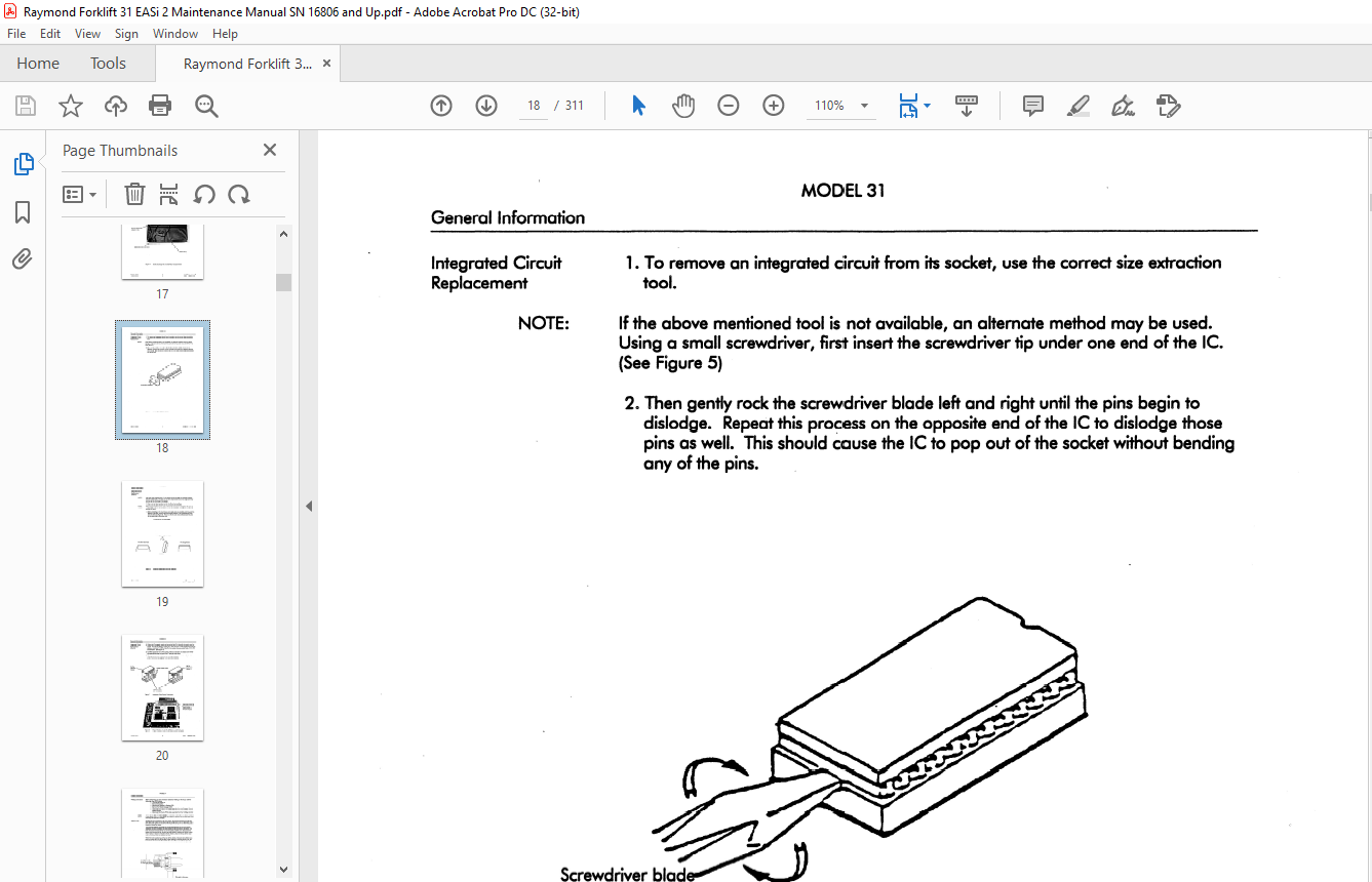
Integrated Circuit Replacement
Welding Instructions
Jacking Truck
Fuses
Standard Torque Data For Bolts
Conversion Table
Decimal Equivalent Chart
Cold Storage Conditioning
Classes Of Cold Storage
Hydraulic System Oil Change Procedure
Drive Unit Procedures
Scheduled Maintenance
Batteries
Battery Cleaning
Electrolyte Process
Battery Cleaning Procedure
Battery Electrical Leakage To Frame Test
Battery Charging
Charging Process
Hydrometer Use
Voltage Check
Adding Water To Battery
Guidelines
Battery History Record
Motors
Motor Cleaning
Brush Care
Maintenance Schedule
Maintenance Inspection Chart
Brush Replacement
Motor Overheating
Motor Test for Open Circuit
Motor Open Circuit Test Procedure
Short Circuit Test – Motors
Short Circuit Test
Armature Shorts
Motor Grounds Test
Grounds – General
Scheduled Maintenance (continued)
Hydraulic
Oil Selection
Changing Reservoir Fluid
Changing Reservoir Filter
Bleeding Hydraulic System
Modes Of Operation
Password Levels
PASSWORD
SUPERWRD
Run Mode
Maintenance Mode (Maint)
Configure Mode (Config)
Learn Mode (Learn)
Entering Program Mode
During Initial Power Up
After Initial Power Up
Learn Mode
Configure Mode
Changing the Access Code
Maintenance Mode
Using Maintenance Mode
Status Code Summary
Informational Codes
Code 00
Code 10
Code 11
Code 12
Code 13
Code 19 (Optional)
Fault Codes
Code 20
Code 21
Code 22
Code 23
Code 24
Code 25
Code 26
Code 27
Code 30
Code 32
Code 34
Code 38
Code 40
Code 41
Code 42
Code 43
Code 44
Code 45
MODEL 31
Table of Contents
Subject
Fault Codes (continued)
Code 49
Code 4A
Code 6C
Code 73
Code 74
Code 75
Code 77
Code 79
Code 78
Code 7C
Code 7E
Code 80
Code 81
Code 83
Code 84
Code 85
Code 86
Code 87
Code 88
Code AO
Code Al
Code A2
Code A3
Code EC
Code ED
Code EF
Analog Tests
Test A00 – PC Sense Voltage
Test AO] – 1 S Sense Voltage
Test A02 – Lift Pump Sense Voltage
Test A03 – B-sense Voltage
Test A04 – Throttle Pot Voltage
Test A05 – Lift/Lower Pot Voltage
Test A06 – Display Remote Lift Sense Voltage
Test A07 – Display Remote Lower Sense Voltage
Test A08 – Traction Motor Temperature Voltage
Test A09 – Lift Pump Motor Temperature Voltage
Test A 10 – Power Panel Temperature Sensor Voltage
Test A 11 – Armature Current Sensor Voltage
Test Al2 – Field Current Sense Voltage
Test A 13 – Pressure Sensor Voltage
Test A 14 – Power Supply + 12 Voltage
Test A 15 – Battery Voltage
Test A 16 – Diagnostic Pendant Sense Voltage
Test A 18 – Remote Lift/Lower Option
Digital Input Tests
Test 100 – Deadman Switch
Test 101 – Remote EPO and/or Unnested Switch
Test 102 – Mast Switch # 1
Test 103 – Mast Switch #2
Digital Input Tests (continued)
Test 105 – Lift Inhibit Mast Switch
Test 106 – Reach Switch
Test 107 – Retract Switch
Test 108 – Tilt Up Switch
Test 109 – Tilt Down Switch
Test 110 · – Sideshift Right Switch
Test 111 – Sideshift Left Switch
Test 112 – Power Panel Temperature Limit Signal
Test 113 – Armature Current Limit Signal
Test 114 – Field Current Limit Signal
Test 115 – Hom Button
Test 116 – Encoder Count
Digital Output Tests
Test 000 – Toggle the PC Contador
Test 001 – Toggle the 1 S Contador
Test 002 – Toggle the P Contador
Test 003 – Toggle the B Contador
Test 004 – Toggle Solenoid DIRA
Test 005 – Toggle Solenoid DIRB
Test 006 – Toggle Reach Solenoid
Test 007 – Toggle Tilt Solenoid
Test 008 – Toggle Sideshift Solenoid
Test 009 – Toggle Equalizing Solenoid (EQ)
Test 010 – Toggle 2ND Stage Solenoid
Test 011 – Toggle Load Hold Solenoid
Test 012 – Proportional Solenoid PVvM Ramp
Test O 13 – Chopper Control Module Enable Signal
Test O 14 – Chopper Control Module PVvM Test
Test 015 – HCM Forward Enable Test
Test O 16 – HCM Reverse Enable Test
Test 017 – HCM PVvM Ramp
Test 018 – Toggle Horn
Test O 19 – Audible Alarm Test
Test 020 – Forward Relay Test
Test 021 – Reverse Relay Test
BSOC (Battery State-of-Charge)
Power Section
Torque Specifications
Decals
Drive Unit Removal
Drive Unit Installation
Drive Unit Axle Seal Replacement
Table of Contents
Subiect
Brake
Braking Process
Brake Adjustment
Brake Assembly/ Adjustment
Without Adjusting Tool
Wrth Adjusting Tool (828-003-804)
Bleeding Brake
Deadman Pedal
Replacing Brake Master Cylinder
Replacing Brake Pads – Stromag
Brake Installation – Stromag
Brake O-ring Seal Replacement-Stromag
Hilliard Brake
Removal
Hilliard Brake Disassembly
Hilliard Brake Reassembly
Steering
System Overview
Relief Valve
Theory of Operation
Steering Adjustment (w/steerable caster)
Initial Adjustments
Caster Adjustment
Service Notes
Elevating Section/ Attachment
Over The Mast Hose/Cable Adjustment
Over The Mast Hose Replacement
Flow Control Replacement (TT)
Equalization Chain Adjustment (TT)
Equalization Chain Removal/Installation (TT)
Equalization Chain Sheave Replacement
Reach Carriage Chain Anchors
Replacing Mast Bumpers
Mechanical Stop Adjustment
Reach Carriage Lubrication Points
Fork Carriage Pivot Pins
Lift Chains
Defect-Cause Chart
Lift Chain Lubrication Procedure
Decal Information
Lift/Lower System
System Overview
Unique System Features
Table of Contents
Subiect
Auxiliary System
Pump
Motor
Reach
Siqeshift
Fork Tilt
Traction System
Power Transistor Theory
Power Transistor Description
Travel Circuit Components
Power Amplifier Components
Wiring Conventions
Chopper Control Module (CCM)
Power Transistor Control
Current Monitoring
Power Panel Temperature
Signal Verification
Power Transistor (Ql)
Snubber Capacitor (Cl)
Snubber Rectifier (REC2)
Snubber Resistor (R4)
Operation of the Travel System
Connecting Battery
Turning Key Switch (Sl) ON – Before Selfrest
Startup Sequence
Selfr est Checks
Turning Key Switch (Sl) ON – After Selfrest
Closing Deadman Switch (S2)
Moving Directional/Speed Control
H-Bridge
Contador Coils
Closed Loop Speed Control
Torque On Demand
Thermal Cut-Back
Current Limiting
“B” Speed (Bypass) Operation
Plugging
Power Transistor (Ql) Test
TM1/TM2 Test
Chopper Control Module Test
HCM Test
Testing Other Electrical Components
RECl and REC4 Test
R4Test
Testing Snubber Capacitor (Cl)
Power Panel Service Information
Power Panel Heat Sensor Replacement
VFC Power Supply Test
EASi2 Reach-Fork®
MODEL 31
Table of Contents
Subiect
Troubleshooting
Troubleshooting Procedure
Wiring – General
Wiring Harness
Shorts to Frame
Voltage to Frame
Troubleshooting intellidrive2
Learn Mode and Troubleshooting
Board and Component Swapping Precautions
Likelihood of Component Failure
Handling Printed Circuit Cards
Truck Completely Inoperative, Sl Is On, No 2-digit Display
Truck Completely Inoperative, 2-digit Display Lit, But No Valid Code
No Lift/fravel OK Selftest OK
During Powerup, Operator’s Display Shows – “Deadman?”
Speed Limited with No Code
No Lift, Travel OK, SelfTest OK
Hydraulic Schematics
Electrical Schematic Legend
Electrical Schematic
IMAGES PREVIEW OF THE MANUAL:
VIDEO PREVIEW OF THE MANUAL:
PLEASE NOTE:
- This is the SAME exact manual used by your dealers to fix your vehicle.
- The same can be yours in the next 2-3 mins as you will be directed to the download page immediately after paying for the manual.
- Any queries / doubts regarding your purchase, please feel free to contact [email protected]
s.m


