

Kubota KX36-3 KX41-3S KX41-3V Excavator Workshop Manual – PDF DOWNLOAD
DESCRIPTION:
Kubota KX36-3 KX41-3S KX41-3V Excavator Workshop Manual – PDF DOWNLOAD
Safety precautions for servicing, disassembly and reassembly
Safety precautions for servicing
Most accidents during servicing arise from carelessness. Please remember that Safety involves both the
welfare of the employees and improved work efficiency.
Safety precautions for Disassembly and reassembly
Machines must be diassembled and assembled efficiently and safely.
It is very important to thoroughly understand the construction and function of the machine, to make all appropriate
preparations, and start operations according to the specified working procedures.
a. Safety measures before starting work
(1)Work clothes
1. Wear specified work cap and clothed.
(Under no circumstances may workers wear
undershirts only.)
Cuffs must be kept buttoned, and any tears
must be mended.)
2. Wear safety shoes.
3. Do not wear cotton gloves when working on
the internal section of engine, reduction
gears or hydrauricunits for repair or others,
or when using a hammer. Wear leather
gloves, however, when hoisting wires.
(2)Inspecting equipment and tools
1. Prepare equipment (cranes, fork lifts, tool,
etc.) required for servicing and inspect for
any problems before starting work.
2. Hammer heads (metal parts) must be firmly
secured to their handles.
3. Check hosting tools (wire ropes, hoisting
chains, etc.) before use.
(3)Keep workshop in order
1. Secure appropriate space needed for disassembly
to the job.
2. Secure a clean, safe place for arranging disassembled
parts.
3. Store volatile substances (gasoline, light oil,
thinner, oily articles, etc.) in appropriate containers
at selected locations to prevent fire
hazards.
TABLE OF CONTENTS:
Kubota KX36-3 KX41-3S KX41-3V Excavator Workshop Manual – PDF DOWNLOAD
WSM_KX36-3_41-3S_41-3V_Service…………………………………………………………… 1
CONTENTS………………………………………………………………………………. 3
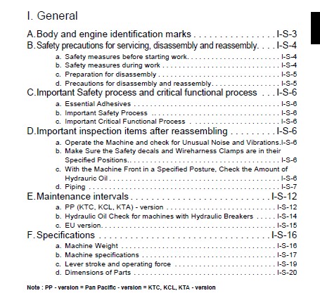
I General……………………………………………………………………………… 5
A. Body and engine identification marks……………………………………………….. 7
B. Safety precautions for servicing, disassembly and reassembly………………………….. 8
a. Safety measures before starting work……………………………………………. 8
(1) Work clothes…………………………………………………………….. 8
(2) Inspecting equipment and tools…………………………………………….. 8
(3) Keep workshop in order……………………………………………………. 8
b. Safety measures during work……………………………………………………. 8
(1) Protectors………………………………………………………………. 8
(2) Team work……………………………………………………………….. 8
(3) Disassembly and assembly………………………………………………….. 8
(4) Cranes………………………………………………………………….. 8
(5) Others………………………………………………………………….. 8
c. Preparation for disassembly……………………………………………………. 9
(1) Cleaning………………………………………………………………… 9
(2) Acceptance inspection…………………………………………………….. 9
(3) Equipment and tools………………………………………………………. 9
d. Precautions for disassembly and reassembly………………………………………. 9
(1) Disassembly……………………………………………………………… 9
(2) Reassembly………………………………………………………………. 9
C. Important Safety process and critical functional process……………………………… 10
a. Essential Adhesives…………………………………………………………… 10
b. Important Safety Process ……………………………………………………… 10
c. Important Critical Functional Process ………………………………………….. 10
D. Important inspection items after reassembling……………………………………….. 10
a. Operate the Machine and check for Unusual Noise and Vibrations…………………….. 10
b. Make Sure the Safety decals and Wireharness Clamps are in their Specified Positions….. 10
c. With the Machine Front in a Specified Posture, Check the Amount of Hydrauric Oil…….. 10
d. Piping………………………………………………………………………. 11
(1) General precautions………………………………………………………. 11
(2) Hydraulic hose…………………………………………………………… 11
(3) Precautions in tightening the bolts and nuts………………………………… 11
(4) Hose screw………………………………………………………………. 12
Metric Size Hose…………………………………………………………….. 12
(5) Joint bodies…………………………………………………………….. 12
(6) Tightening torque table for hose clamp (Screw type)………………………….. 13
(7) Nuts for piping………………………………………………………….. 13
(8) Tightening torque of bolts and nuts………………………………………… 14
(9) Types and materials of bolts and nuts………………………………………. 14
(10) Washer-equipped elbow……………………………………………………. 15
E. Maintenance intervals…………………………………………………………….. 16
a. PP (KTC, KCL, KTA) – version…………………………………………………… 16
b. Hydraulic Oil Check for machines with Hydraulic Breakers………………………….. 18
c. EU version…………………………………………………………………… 19
F. Specifications…………………………………………………………………… 20
a. Machine Weight……………………………………………………………….. 20
(1) KE, KDG, KUK version……………………………………………………… 20
(2) PP (KTC, KCL, KTA) version………………………………………………… 20
b. Machine specifications………………………………………………………… 21
(1) EU version………………………………………………………………. 21
(2) PP version………………………………………………………………. 22
c. Lever stroke and operating force……………………………………………….. 23
d. Dimensions of Parts…………………………………………………………… 24
(1) Front pins………………………………………………………………. 24
(2) Bush Dimansion…………………………………………………………… 25
(3) Track toller, idler, sprocket……………………………………………… 26
(4) Dozer…………………………………………………………………… 27
(5) Bucket………………………………………………………………….. 28
(6) Arm…………………………………………………………………….. 29
(7) Parts weight…………………………………………………………….. 30
(8) Water and Oil Quantity……………………………………………………. 32
(9) Rubber crawler…………………………………………………………… 32
(10) Product inspection specifications : KBM products to EU-version……………….. 33
II Machine Body………………………………………………………………………… 35
A. Front attachment…………………………………………………………………. 37
a. Pin, bush and shim installation………………………………………………… 37
(1) Swing cylinder, swing bracket, boom………………………………………… 37
(2) Arm, bucket link…………………………………………………………. 38
(3) Blade, blade cylinder and truck cylinder……………………………………. 39
(4) Clearance adjustment……………………………………………………… 41
b. Instruction to press in the bushing…………………………………………….. 42
(1) Bush installation steps…………………………………………………… 42
(2) Installing direction of dust seal………………………………………….. 42
(3) Installation of thrust collar on the swing bracket…………………………… 43
(4) Swing bracket pin & bush………………………………………………….. 44
(5) Measuring the swing bracket looseness………………………………………. 45
(6) Service tip to ease customer complain………………………………………. 46
c. Greasing points………………………………………………………………. 47
B. Upper Structure………………………………………………………………….. 50
a. Swivel bearing……………………………………………………………….. 50
b. Travel lever…………………………………………………………………. 51
c. Accelarator lever…………………………………………………………….. 53
d. Dozer lever………………………………………………………………….. 55
e. Swing & SP pedal……………………………………………………………… 57
f. Control valve links…………………………………………………………… 59
g. Limit switch installation……………………………………………………… 60
h. Seat belt……………………………………………………………………. 61
C. Undercarrige…………………………………………………………………….. 62
a. Track tension device………………………………………………………….. 62
b. Track Roller…………………………………………………………………. 64
III Engine…………………………………………………………………………….. 65
A. Engine accessories……………………………………………………………….. 37
a. Engine mount…………………………………………………………………. 37
b Air cleaner…………………………………………………………………… 68
c. Radiator…………………………………………………………………….. 70
d. Muffler……………………………………………………………………… 74
e. Pump coupling………………………………………………………………… 76
f. Fuel tank……………………………………………………………………. 77
g. Fuel tank cushion…………………………………………………………….. 78
h. Fuel hoses…………………………………………………………………… 79
B. Engine WSM : D902 -E……………………………………………………………… 81
C. Engine WSM : D782 -B………………………………………………………………183
IV Hydraulic System……………………………………………………………………..219
A. Troubleshooting…………………………………………………………………..221
a. Common circuit………………………………………………………………..221
b. Hydraulics……………………………………………………………………224
c. Pump…………………………………………………………………………227
d. Motor………………………………………………………………………..228
e. Swivel performance…………………………………………………………….229
f. Traveling performance………………………………………………………….231
g. Electrical components………………………………………………………….233
(1) Engine components…………………………………………………………233
(2) Panel components (with key switch turned ON)…………………………………234
(3) Panel components (with engine started)………………………………………235
(4) Others…………………………………………………………………..236
B. Testing………………………………………………………………………….237
a. Testing Instruments & special tools……………………………………………..237
b. Pump flow…………………………………………………………………….239
c. Pressure measurement…………………………………………………………..240
(1) Pilot pressure……………………………………………………………240
(2) Main relief valve…………………………………………………………242
(3) Overload relief valve……………………………………………………..244
(4) Swivel brake valve pressure………………………………………………..247
d. Drain measurement……………………………………………………………..248
(1) Traveling motor…………………………………………………………..248
(2) Swivel motor……………………………………………………………..249
e. Measurement of block performance………………………………………………..250
(1) Swivel…………………………………………………………………..250
(2) Traveling………………………………………………………………..251
f. Operating speed……………………………………………………………….252
(1) Checking each operating speed………………………………………………252
(2) Boom cylinder…………………………………………………………….252
(3) Arm cylinder……………………………………………………………..252
(4) Bucket cylinder…………………………………………………………..253
(5) Swing cylinder……………………………………………………………253
(6) Dozer cylinder……………………………………………………………253
(7) Swivel speed……………………………………………………………..254
(8) Traveling speed…………………………………………………………..254
g. Straight travel performance…………………………………………………….254
h. Cylinder natural fall amount……………………………………………………255
i. Control and Traveling lever operating force………………………………………255
j. Lever stroke………………………………………………………………….255
C. Specifications……………………………………………………………………256
a. Pump specifications……………………………………………………………256
b. Relief Valve………………………………………………………………….258
(1) Bench set data……………………………………………………………258
(2) Machine set data (at the pump gauge port)……………………………………259
c. Swivel performance…………………………………………………………….260
d. Traveling performance………………………………………………………….260
e. Cylinder……………………………………………………………………..262
(1) Speed……………………………………………………………………262
(2) Natural fall……………………………………………………………..262
(3) Cylinder maintenance data………………………………………………….263
f. Service port flow amount……………………………………………………….264
g. Motor oil drain amount test sample………………………………………………264
(1) Travel motor……………………………………………………………..264
(2) Swivel motor……………………………………………………………..264
h. Quality Specifications…………………………………………………………265
D. Disassembling and reassembling……………………………………………………..275
a. Pump…………………………………………………………………………275
(1) Component of pump…………………………………………………………275
(2) Adaptor installation (KX36-3 EU, KX41-3 EU)………………………………….277
(3) Adaptor installation………………………………………………………278
(4) Disassembling and reassembling……………………………………………..279
b. Control valve…………………………………………………………………286
(1) Component of control valve…………………………………………………286
(2) Adaptor installation (KX36-3, KX41-3 EU)…………………………………….287
(3) Adaptor installation (KX41-3 PP)……………………………………………289
(4) Inner parts of control valve……………………………………………….292
(5) Disassembling and reassembling……………………………………………..304
c. Pilot valve (PP version)……………………………………………………….330
(1) Components of pilot valve………………………………………………….330
(2) Adaptor installation………………………………………………………331
(3) Pilot hose connection……………………………………………………..332
(5) Disassembling and assembling……………………………………………….336
c. Pilot valve (EU version)……………………………………………………….353
d. Swivel motor (KX41-3 PP)……………………………………………………….364
(1) Component of swivel motor………………………………………………….364
(2) Cross-sectional View of Swivel Motor………………………………………..365
(3) Adaptor Installation………………………………………………………366
d. Swivel motor (KX36-3 EU, KX41-3 EU)……………………………………………..377
(1) Component of swivel motor………………………………………………….377
(2) Adaptor Installation………………………………………………………378
e. Rotary Joint………………………………………………………………….379
(1) Components of Rotary Joint (KX41-3 PP)………………………………………379
(2) Components of Rotary Joint (KX36-3 EU, KX41-3 EU)…………………………….380
(2) Adaptor Installation………………………………………………………383
(2) Adaptor installation (KX41-3V PP)…………………………………………..386
(3) Hose connection…………………………………………………………..387
(4) Assembling of the rotary joint……………………………………………..391
(5) Disassembling of the Rotary Joint from machine……………………………….392
f. Travel motor………………………………………………………………….394
(1) Componet of travel motor…………………………………………………..394
(2) Adaptor installation………………………………………………………396
(3) Hose connection…………………………………………………………..397
(4) Disassembly and reassembly…………………………………………………398
g. Cylinder……………………………………………………………………..412
(1) Components and specifications (KX41-3 EU)……………………………………412
(2) Disassembling and reassembling……………………………………………..418
h. Unload valve (KX41-3 PP)……………………………………………………….421
(1) Location of unload valve…………………………………………………..421
(2) adaptor installation………………………………………………………422
(3) Hose connection…………………………………………………………..423
h. Unload valve (KX36-3 EU, KX41-3 EU)……………………………………………..424
i. Change valve (Dozer, Track)(KX41-3 PP)…………………………………………..425
(1) Location of change valve…………………………………………………..425
(2) Components of change valve…………………………………………………426
(3) Adaptor installation………………………………………………………427
(4) Hose connection…………………………………………………………..428
i. Change valve (Dozer, Track) (KX36-3 EU, KX41-3 EU)………………………………..429
j. TPSS valve (TPSS = Two patern selection system) (PP Version)……………………….430
(1) Components of TPSS valve…………………………………………………..430
(2) Adaptor installation………………………………………………………431
(4) Hose connection…………………………………………………………..432
k. Oil tank……………………………………………………………………..433
l. Delivery hose (KX41-3 PP)………………………………………………………434
m. Return hose (KX41-3 PP)………………………………………………………..435
n. Table of hoses (KX41-3 PP)……………………………………………………..436
O. Pilot Hose (KX36-3 EU, KX41-3 EU)……………………………………………….441
(2) Table of Hoses (KX36-3 EU, KX41-3 EU)……………………………………….442
P. Delivery Travel, Swivel, Blade, Swing Hose (KX36-3 EU, KX41-3 EU)…………………..443
Q. Suction, Return Hose (KX36-3 EU, KX41-3 EU)………………………………………445
(1) Suction Hose……………………………………………………………..445
(2) Return Hose………………………………………………………………446
(3) Table of Hoses……………………………………………………………447
R. Table of Hoses (KX36-3 EU, KX41-3 EU)……………………………………………448
V Electrical system……………………………………………………………………..451
A. Troubleshoothing………………………………………………………………….453
a. General………………………………………………………………………453
(1) How to diagnose…………………………………………………………..453
b. Failure display and diagnosis criteria on the meter panel………………………….454
c. Engine……………………………………………………………………….455
d. Others……………………………………………………………………….456
B. Kubota Intelligent Control System…………………………………………………..457
a. Navigation list of messages…………………………………………………….457
b. Meter display…………………………………………………………………459
n Display Selector Switch……………………………………………………..459
n Charge Lamp………………………………………………………………..459
n Oil Lamp…………………………………………………………………..459
n Glow Lamp………………………………………………………………….459
n LCD Display for Usual Operation………………………………………………460
n LCD Display for Warning……………………………………………………..461
n Warning Lamp……………………………………………………………….462
c. Fuses………………………………………………………………………..463
n Replacing Fuses…………………………………………………………….463
n Fuse Capacities and Circuits…………………………………………………463
n Auxiliary Electric………………………………………………………….463
n Slow Blow Fuse……………………………………………………………..463
C. Wire harness installation………………………………………………………….465
a. Precautions…………………………………………………………………..465
b. Engine earth, starter switch……………………………………………………466
c. Main harness………………………………………………………………….467
D. Others, for your reference…………………………………………………………473
a. Photo samples taken from Hirakata assembly line…………………………………..473
b. Photo samples taken from KBM assembly line : EU – version………………………….480
IMAGES PREVIEW OF THE MANUAL:


VIDEO PREVIEW OF THE MANUAL:

PLEASE NOTE:
- This is the SAME manual used by the dealers to troubleshoot any faults in your vehicle. This can be yours in 2 minutes after the payment is made.
- Contact us at [email protected] should you have any queries before your purchase or that you need any other service / repair / parts operators manual.
S.V


