Kubota V2607 cr e4b V2607 cr te4b V2607 cr tie4b Doc Only V3307 cr te4b V3307 cr tie4 Workshop Manual
FILE DETAILS:
LANGUAGE:ENGLISH
PAGES:221
DOWNLOADABLE:YES
FILE TYPE:PDF
VIDEO PREVIEW OF THE MANUAL:
IMAGES PREVIEW OF THE MANUAL:


DESCRIPTION:
Kubota V2607 cr e4b V2607 cr te4b V2607 cr tie4b Doc Only V3307 cr te4b V3307 cr tie4 Workshop Manual
This Workshop Manual tells the servicing personnel about the mechanism, servicing and maintenance of the V2607-CR-E4B, V2607-CR-TE4B and V3307-CR-TE4B. It contains 4 parts:
“Information”, “General”, “Mechanism” and “Servicing”.
1) Information
This section primarily contains information below.
• Safety First
• Specification
• Performance Curve
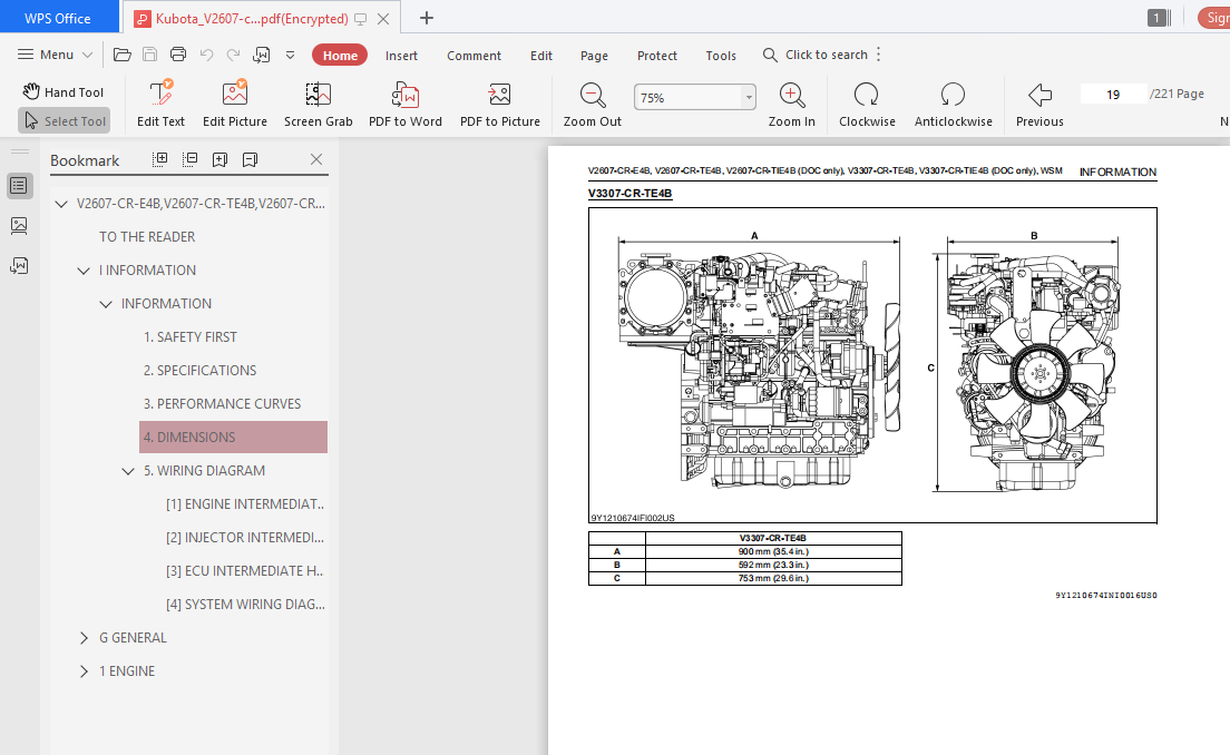
• Dimension
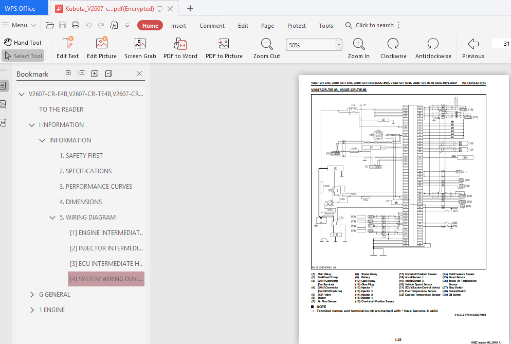
• Wiring Diagram
2) General
This section primarily contains information below.
• Engine Identification
• Muffler Full Assembly Identification
• General Precautions
• Maintenance Check List
• Check and Maintenance
• Special Tools
3) Mechanism
This section contains information on the structure and the function of the unit. Before you continue
with the subsequent sections, make sure that you read this section.
Refer to Workshop Manual (Code No. 9Y021-01870) for the diesel engine mechanism that this
workshop manual does not include.
4) Servicing:
This section primarily contains information below.
• Troubleshooting
• Servicing Specifications
• Tightening Torques
• Checking, Disassembling and Servicing
All illustrations, photographs and specifications contained in this manual are of the newest information available at the time of publication.
KUBOTA reserves the right to change all information at any time without notice. Since this manual includes many models, information or illustrations and photographs can show more than one model.
TABLE OF CONTENTS:
Kubota V2607 cr e4b V2607 cr te4b V2607 cr tie4b Doc Only V3307 cr te4b V3307 cr tie4 Workshop Manual
1 SAFETY FIRST I-1
2 SPECIFICATIONS I-5
3 PERFORMANCE CURVES I-7
4 DIMENSIONS I-12
5 WIRING DIAGRAM I-17
[1] ENGINE INTERMEDIATE HARNESS (ENGINE SIDE HARNESS) I-17
[2] INJECTOR INTERMEDIATE HARNESS
(ENGINE SIDE HARNESS) I-19
[3] ECU INTERMEDIATE HARNESS (ONE SIDE HARNESS) I-20
[4] SYSTEM WIRING DIAGRAM I-25
PLEASE NOTE:
- This is the SAME manual used by the dealers to troubleshoot any faults in your vehicle. This can be yours in 2 minutes after the payment is made.
- Contact us at [email protected] should you have any queries before your purchase or that you need any other service / repair / parts operators manual.


