

Fendt Loader Wagon Tigo 65 XR Tigo 65 XR D Tigo 75 XR Tigo 75 XR D Tigo 90 XR Tigo 90 XR D Tigo 100 XR Tigo 100 XR D Operator’s Manual – PDF
DESCRIPTION:
Fendt Loader Wagon Tigo 65 XR Tigo 65 XR D Tigo 75 XR Tigo 75 XR D Tigo 90 XR Tigo 90 XR D Tigo 100 XR Tigo 100 XR D Operator’s Manual – PDF
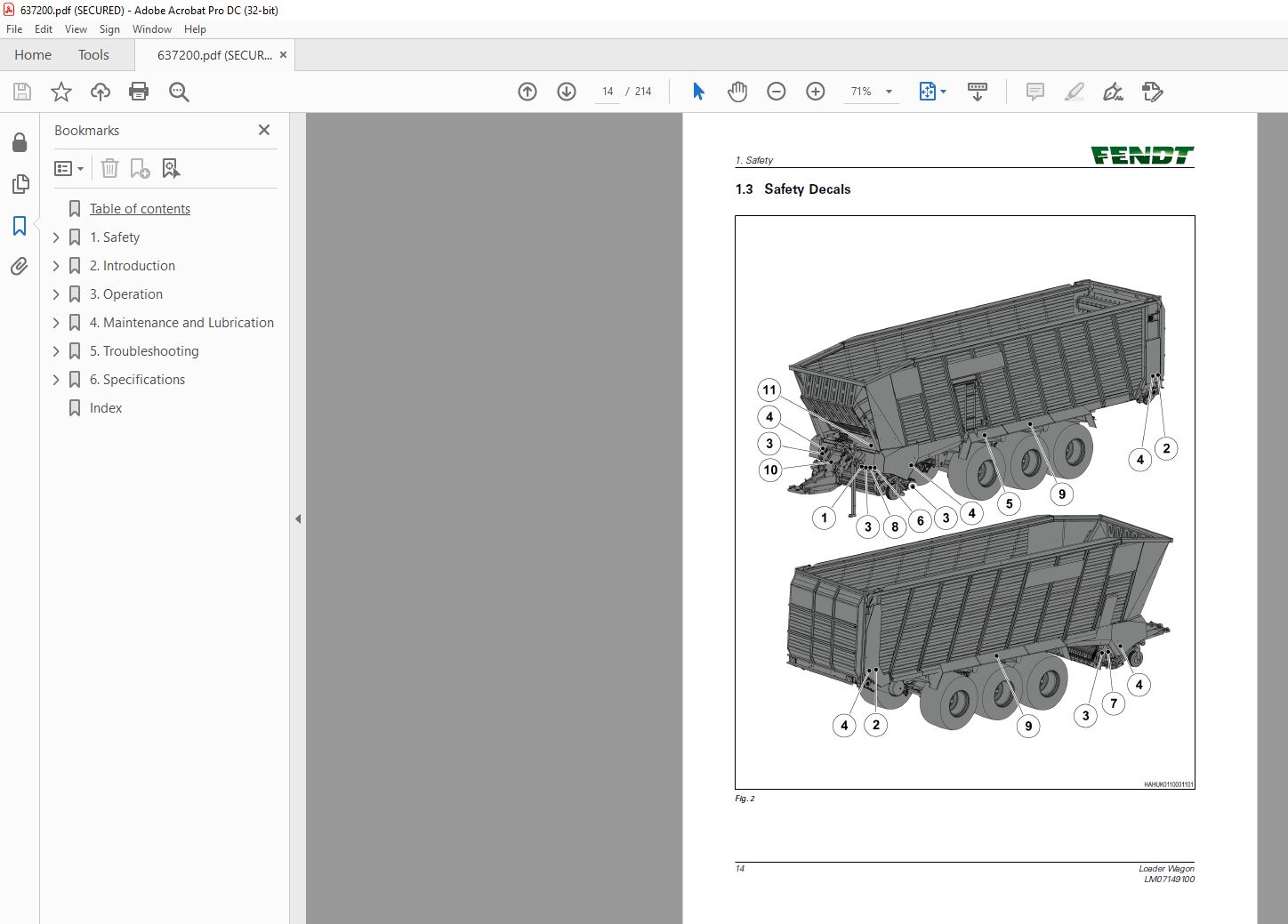
1.2 Safety Instructions
- YOU are responsible for the SAFE operation and maintenance of your machine.
- YOU must make sure that each person who operates or does work on the machine understands all the SAFETY data in this manual.
- YOU are the key to safety. Good safety procedures prevent accidents to you and each person near you. Make these procedures a set part of your safety sequence.
- Make sure that EVERYONE who operates, does maintenance or works near to the machine obeys the safety precautions.
Follow the safety sequence to prevent the risk of injury or death:
- Owners must complete training with all operators before they operate the machine. This training must be done a minimum of each year
- The operator must read, understand and obey all safety and operation instructions in the manual
- A person who did not read and understand all safety and operation instructions must not operate the machine
- Do not change the equipment. Adjustments not approved by the manufacturer can change the function of the machine and cause damage or personal injury
- Only use approved replacement parts and make sure that only approved technicians do the repair procedures.
1.2.1 General Safety
- Read and understand the manual and all safety decals, before you operate the machine
- Follow all safety regulations, in this manual and instructions or warnings shown on the machine
- Only use the machine for its correct operation
- Only approved persons that understand the operator manual, can operate, drive and do maintenance on the machine
- Keep persons and objects away from parts that move
- Make sure that the installation of all the safety guards and protection devices is correct and they operate correctly
- Always use a tractor with a cabin. Make sure that you close the cabin of the tractor during operation to decrease the quantity of sound. High quantity of sound can cause reduction in hearing
- Put on the correct protective clothing and equipment (gloves, safety glasses and ear protectors)
- Look for hazards and signs of defects (leakage and noise)
- Keep the safety decals clean to make sure that you can see them at all times. Replace safety decals that are missing or you cannot see
- Know the telephone number for emergency medical help in your area
- Speak to your local dealer, if you are not sure of one or more items
- Only connect the machine to the tractor using the procedures in this manual. Only connect the machine to a tractor trailer hitch with your local regulations approval
- Follow the safety instructions on the PTO shaft.
- Make sure that the front axle weight of the tractor is sufficient. Make sure that you do not have more weight than the maximum permitted on the rear axle
- Do not connect the machine to the tractor when the tractor engine is in operation
- Release the pressure from the hydraulic system before you connect or disconnect the hydraulic hoses. Refer to the manual of the tractor
- If the machine has a pneumatic or hydraulic brake, connect the brake hose(s) to the tractor
- Make sure that all safety guards and protection devices are in position
- The PTO shaft must not be used with a missing or damaged guard. You must always use the correct restraining system
- Only used manufacturer approved replacement parts when you replace any part of the PTO shaft
- Do not stand on the PTO or the PTO drive shaft
- Always attach the restraining chain to the PTO
- Do not remove a blockage by hand or by foot. Always use an applicable tool
- Make sure that you set the pressure of the tyres of the transport wheels to the pressure specified. Do not put less than or more than the specified pressures in the tyres
- We recommend to only replace the first tyres with tyres that have speed category and load specifications the same or better than the values in the tyre pressure table. If you do not do this, it can cause dangerous problems.
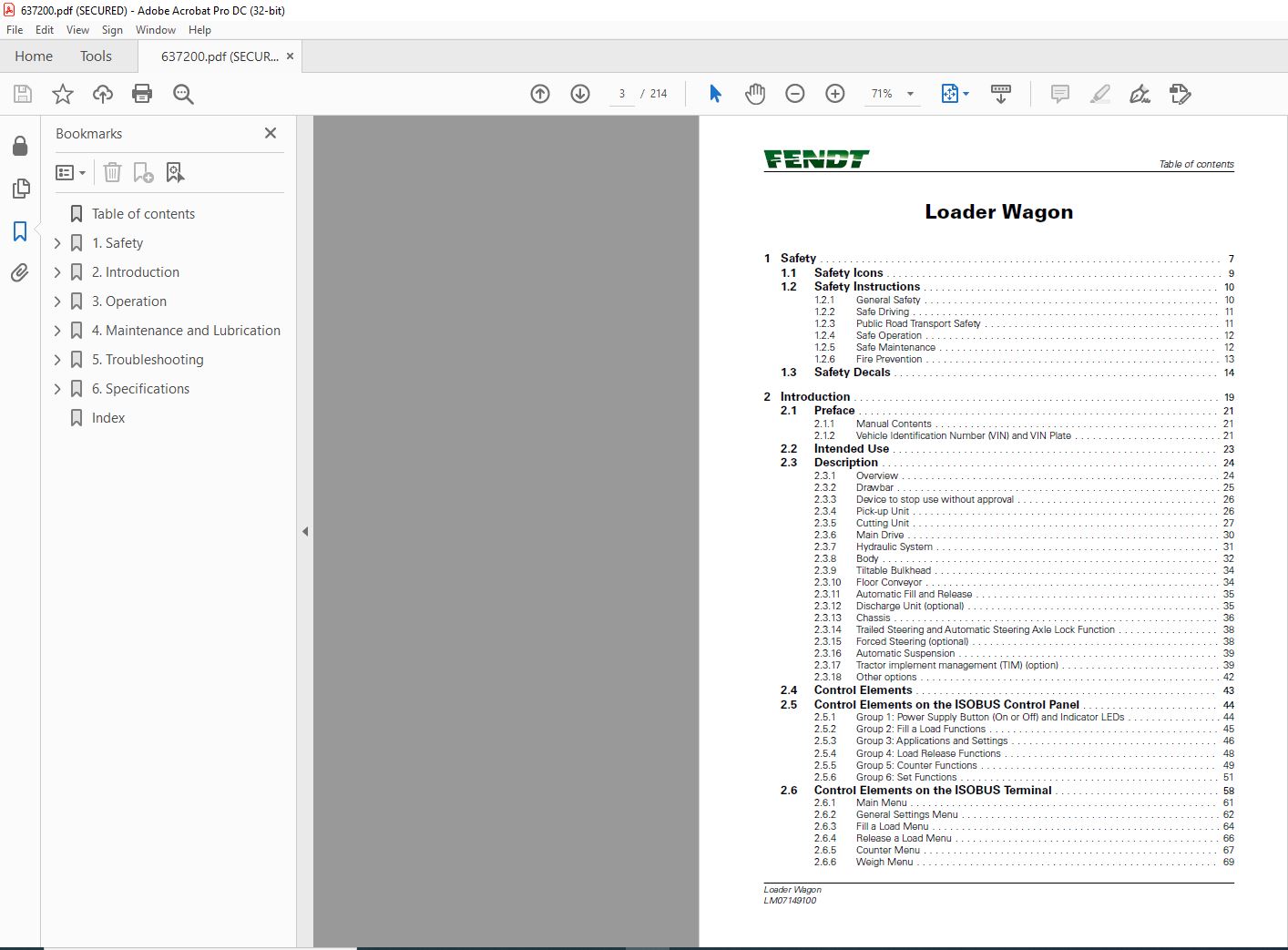
TABLE OF CONTENTS:
Fendt Loader Wagon Tigo 65 XR Tigo 65 XR D Tigo 75 XR Tigo 75 XR D Tigo 90 XR Tigo 90 XR D Tigo 100 XR Tigo 100 XR D Operator’s Manual – PDF
1 Safety 7
11 Safety Icons 9
12 Safety Instructions 10
121 General Safety 10
122 Safe Driving 11
123 Public Road Transport Safety 11
124 Safe Operation 12
125 Safe Maintenance 12
126 Fire Prevention 13
13 Safety Decals 14
2 Introduction 19
21 Preface 21
211 Manual Contents 21
212 Vehicle Identification Number (VIN) and VIN Plate 21
22 Intended Use 23
23 Description 24
231 Overview 24
232 Drawbar 25
233 Device to stop use without approval 26
234 Pick-up Unit 26
235 Cutting Unit 27
236 Main Drive 30
237 Hydraulic System 31
238 Body 32
239 Tiltable Bulkhead 34
2310 Floor Conveyor 34
2311 Automatic Fill and Release 35
2312 Discharge Unit (optional) 35
2313 Chassis 36
2314 Trailed Steering and Automatic Steering Axle Lock Function 38
2315 Forced Steering (optional) 38
2316 Automatic Suspension 39
2317 Tractor implement management (TIM) (option) 39
2318 Other options 42
24 Control Elements 43
25 Control Elements on the ISOBUS Control Panel 44
251 Group 1: Power Supply Button (On or Off) and Indicator LEDs 44
252 Group 2: Fill a Load Functions 45
253 Group 3: Applications and Settings 46
254 Group 4: Load Release Functions 48
255 Group 5: Counter Functions 49
256 Group 6: Set Functions 51
26 Control Elements on the ISOBUS Terminal 58
261 Main Menu 61
262 General Settings Menu 62
263 Fill a Load Menu 64
264 Release a Load Menu 66
265 Counter Menu 67
266 Weigh Menu 69
Table of contents
Loader Wagon
LM07149100
267 Weigh System Calibration Menu 70
268 Maintenance Menu 71
269 Set menu 72
2610 Aux Menu 77
27 Control Elements on the Machine 79
3 Operation 81
31 First Use 83
311 Prepare for the First Use 83
312 Assembly by the Dealer 83
313 Remove the blockage of the hydraulic system for the forced steering axle 83
314 Adjust the Automatic Load-Sensitive Brake System (pneumatic brakes) 84
315 Adjust the Load Sensing System 84
316 Adjust the Height of the Hydraulic Drawbar 85
317 Align the Forced Steering System 86
318 Install the PTO Overload Protection 87
319 Adjust the Length of the PTO Shaft 88
3110 Connect a Preservative Application System (optional) 89
3111 Connect the Tractor implement management (TIM) for the first time (option) 90
32 Connect the Machine to the Tractor 97
321 Connect the Lighting Cable 97
322 Connect the User Interface(s) 97
323 Connect to the ISOBUS Control Panel 98
324 Connect to the ISOBUS Socket 98
325 Connect the Hydraulic and Pneumatic Hoses 98
326 Connect the Drawbar Coupling 100
327 Connect the Forced Steering System (optional) 101
328 Connect the Hydraulic Break-Away System (optional) 102
329 Connect the Power Take Off (PTO) Shaft 102
33 Transport Position and Driving 103
331 Put the Parking Jack in the Driving Position 103
332 Drain the Air Container of the Pneumatic Brake System (optional) 104
34 Prepare the Machine for a Load 106
341 Install the Intake Duct Cover Plate (optional) for Loading with a Forage Harvester 106
342 Adjust the Working Height of the Pick-up 106
343 Adjust the Height of the Touch Roller (optional) 107
344 Adjust the Height of the Wind Guard 108
345 Adjust the Pressure on the Hydraulic Pick-up Suspension (optional) 109
346 Adjust the Distance Between the Knives and the Rotor 109
347 Select the Number of Knives 111
348 Set the Crop Compression 111
349 Set the Crop Compression Value on the ISOBUS control panel 111
3410 Set the Crop Compression Value on the ISOBUS Terminal 112
3411 Set and Start a Job Counter on the ISOBUS control panel 112
3412 Select and Start a Counter on the ISOBUS Terminal 113
3413 Configure the TIM and set the target speed 113
35 Fill the machine 115
351 Fill the Machine Automatically 115
352 Fill the Machine Manually 117
36 Weigh the load (with optional weigh system) 120
361 Weigh Manually 120
37 Empty the Machine 121
371 Empty the Machine Automatically 121
372 Empty the Machine Manually 123
38 Disconnect the Machine From the Tractor 125
381 Put the Parking Jack in the Park Position 125
Table of contents
Loader Wagon
LM07149100
382 Engage the Parking Brake and Put the Wheel Chocks Against a Wheel 127
4 Maintenance and Lubrication 129
41 Maintenance After the First Operation 131
42 Preventive Maintenance Schedule 132
43 Other Maintenance 135
44 Maintenance Before and After Storage 136
45 Maintenance Procedures 138
451 Clean the Machine 138
452 Replace the Hydraulic Filter 138
453 Replace a Transport Wheel 139
46 Maintenance on the PTO Shaft and the Main Drive 142
461 Apply Grease to the PTO Shaft 142
462 Apply Grease to the Main Shaft Clutch 143
463 Replace the Oil of the Main Shaft Gearbox 143
47 Maintenance on the Drawbar 144
471 Apply Grease to the Drawbar Coupling 144
48 Maintenance on the Pick-up Unit 145
481 Apply Grease to the Pivots of the Pick-up Guide Wheels 145
49 Maintenance on the Cutting Unit 146
491 Sharpen the Knives or Replace the Knives 146
492 Make the Knives Accessible for Maintenance 146
493 Remove a Knife 147
494 Install a Knife After Removal 148
495 Move the Knife Assembly Back to the Working Position 148
496 Adjust the End Stop of the Knife Assembly 149
497 Apply Grease to the Bearing of the Rotor Feeder 149
498 Replace the Grease of the Gearbox of the Rotor Feeder 150
410 Maintenance on the Floor Conveyor 151
4101 Adjust the Tension in the Chains of the Floor Conveyor 151
4102 Apply Grease to the Drive Shaft Bearings of the Floor Conveyor 151
4103 Apply Grease to the Running Wheel Bearings of the Floor Conveyor 152
4104 Replace the Gearbox Oil of the Floor Conveyor 152
411 Maintenance on the Discharge Unit (optional) 153
4111 Adjust the Tension and Lubricate the Drive Chains of the Discharge Unit 153
4112 Apply Grease to the Drive Shaft of the Discharge Unit 153
4113 Replace the Oil of the Rear Gearbox of the Discharge Unit 154
4114 Replace the Oil of the Front Gearbox of the Discharge Unit 155
412 Maintenance on the Chassis 157
4121 Apply Grease to the Bearings of the Steering Spindles 157
4122 Apply Grease to the Pivot Points of the Chassis (bogie suspension) 157
4123 Apply Grease to the Locking Cylinder of the Trailed Steering 157
4124 Apply Grease to the Brake Camshafts 158
4125 Apply Grease to the Slack Adjuster 158
4126 Apply Grease to the Damping Cylinders (hydropneumatic suspension) 159
4127 Measure the Thickness of the Brake Linings 159
4128 Examine the Working of the Slack Adjuster 160
4129 Adjust the Slack Adjuster 160
41210 Replace the Grease of the Wheel Hub Bearings 160
41211 Adjust the Wheel Hub Bearings 162
41212 Tighten the Axle Assemblies (bogie suspension) 163
41213 Tighten the Spring Mounting Brackets (bogie suspension) 163
41214 Examine and Tighten the Spring Bolts (hydropneumatic suspension) 163
41215 Clean the Filters of the Pneumatic Brake System (if present) 164
41216 Torque Tighten the Vertical Support Screws 165
Table of contents
Loader Wagon
LM07149100
413 Calibrate the Weighing System (optional) 170
4131 Weigh on the Weighbridge 170
4132 Weigh with the Weighing System and Calibrate 170
5 Troubleshooting 173
51 Problems and Suggested Solutions 175
52 Error Messages 177
53 Acknowledge the Error Message 179
6 Specifications 181
61 Specifications 183
62 Hydraulic Diagrams 185
621 Icons Used in the Diagrams 185
622 Hydraulic Base Diagram 186
623 Hydraulic Diagram of the Pick-up Suspension (optional) 187
624 Hydraulic Diagram of the Hydropneumatic Suspension (optional) 187
625 Hydraulic Diagram of the Forced Steering System (optional) 188
626 Table of the Actuators 189
627 Layout of the Solenoid Valves 190
628 Control Diagram of the Solenoid Valves 190
63 Electric Diagrams 192
631 Abbreviations of Wire Colors and Wire Functions 192
632 Table of the Sensors 192
633 Junction Box 194
634 Wiring Loom X1 A-K 196
635 Wiring Loom X1 L-Y 198
636 Wiring Loom X2 A-K 200
637 Wiring Loom X2 L-Y 202
638 ISOBUS Cable X3 203
639 Standard Adapter Cable (LM98104156) 204
6310 Lighting Diagram 206
64 Tables of Standard Torques for Nuts and Bolts 207
65 Table of Standard Wheel Nut Torques 208
66 Table of Standard Tyre Pressures 209
7 Index 211
Table of contents
VIDEO PREVIEW OF THE MANUAL:

IMAGES PREVIEW OF THE MANUAL:

PLEASE NOTE:
- This is the SAME exact manual used by your dealers to fix your vehicle.
- The same can be yours in the next 2-3 mins as you will be directed to the download page immediately after paying for the manual.
- Any queries / doubts regarding your purchase, please feel free to contact [email protected]
S.M


