

2EZGO 2FIVE ELECTRIC 2PASSENGER 4PASSENGER SERVICE MANUAL(ELECTRIC) – PDF DOWNLOAD
DESCRIPTION:
EZGO 2FIVE ELECTRIC 2PASSENGER 4PASSENGER SERVICE MANUAL(ELECTRIC) – PDF DOWNLOAD
48V ELECTRIC POWERED VEHICLES 2Five 2 PASSENGER 2Five 4 PASSENGER
GENERAL:
- Many vehicles are used for a variety of tasks beyond their original intended use. It is impossible to anticipate and warn against every possible combination of circumstances that may occur. Warnings cannot replace good common sense and prudent driving practices. Common sense and prudent driving practices do more to prevent accidents and injury than warnings and instructions can provide.
- Anyone operating the vehicle must read the entire owner’s guide provided with the purchase of the vehicle, paying particular attention to the CAUTIONS, WARNINGS and DANGERS within. For any questions or concerns, contact the closest representative, or write to the address on the back cover of this publication, Attention: Customer Care Department.
- Textron Specialized Vehicles (TSV) reserves the right to make design changes without obligation to make these changes on units previously sold. The information contained in this manual is subject to change without notice. TSV is not liable for errors in this manual or for incidental or consequential damages that result from the use of the material in this manual.
- This vehicle conforms to the current applicable standard for safety and performance requirements. This vehicle is designed and manufactured for off-road use. It does not conform to Federal Motor Vehicle Safety Standards and is not equipped for operation on public streets. Some communities may permit these types of vehicles to be operated on their streets on a limited basis and in accordance with local ordinances.
- Ensure all electrical accessories are grounded directly to the negative (-) battery post. Never use the chassis or body as a ground connection. Refer to GENERAL SPECIFICATIONS for vehicle seating capacity. Do not exceed number of occupants indicated.
TABLE OF CONTENTS:
EZGO 2FIVE ELECTRIC 2PASSENGER 4PASSENGER SERVICE MANUAL(ELECTRIC) – PDF DOWNLOAD
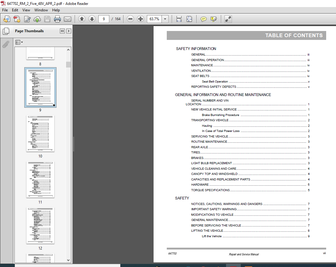
SAFETY INFORMATION
GENERAL iii
GENERAL OPERATION iii
MAINTENANCE iv
VENTILATION iv
SEAT BELTS iv
Seat Belt Operation v
REPORTING SAFETY DEFECTS v
GENERAL INFORMATION AND ROUTINE MAINTENANCE
SERIAL NUMBER AND VIN
LOCATION 1
NEW VEHICLE INITIAL SERVICE 1
Brake Burnishing Procedure 1
TRANSPORTING VEHICLE 2
Hauling 2
In Case of Total Power Loss 2
SERVICING THE VEHICLE 3
ROUTINE MAINTENANCE 3
REAR AXLE 3
TIRES 3
BRAKES 3
LIGHT BULB REPLACEMENT 3
VEHICLE CLEANING AND CARE 4
CANOPY TOP AND WINDSHIELD 4
CAPACITIES AND REPLACEMENT PARTS 4
HARDWARE 5
TORQUE SPECIFICATIONS 5
SAFETY
NOTICES, CAUTIONS, WARNINGS AND DANGERS 7
IMPORTANT SAFETY WARNING 7
MODIFICATIONS TO VEHICLE 7
GENERAL MAINTENANCE 7
BEFORE SERVICING THE VEHICLE 7
LIFTING THE VEHICLE 8
Lift the Vehicle
Lift Rear of Vehicle Only 9
Lift Front of Vehicle Only 9
Lower the Vehicle 9
BODY
GENERAL 11
BODY COMPONENT REPLACEMENT 12
Front Fascia and Front Bumper 12
Rocker Panels 13
Floor Mat 13
Cowl and Instrument Panel 13
Front Splash Guard 14
Seat Back Assembly 15
Fender Liner 15
Rear Body 16
Rear Bumper 17
Bagwell Closeout 17
Floorboard 17
Sweater Basket 18
2 + 2 REAR FACING SEAT AND FOOT REST 19
FRAME 21
BODY CARE MAINTENANCE 22
Cleaning 22
PAINTING 22
Light Scratches 22
Minor Scratches 22
Larger Scratches 23
Complete Panel Repair 23
BATTERIES AND CHARGING
SAFETY 26
BATTERY 26
BATTERY MAINTENANCE 26
At Each Charging Cycle 26
Monthly 27
Electrolyte Level and Water 27
Cleaning Batteries 28
Battery Removal and Installation 28
Prolonged Storage 31
Battery Charging 31
FAULT TESTING 32
Hydrometer 32
Using A Hydrometer 33
BATTERY CHARGER
CHARGER DESCRIPTION 35
UNDERSTANDING THE CHARGER 35
LED DISPLAY INFORMATION 36
LED Operation Codes 36
LED Fault Code 36
MAINTENANCE INSTRUCTIONS 36
REPLACING THE CHARGER WITH DC TO DC CONVERTER 36
Removal 36
Installation 37
BRAKES
GENERAL 39
ROUTINE MAINTENANCE 39
Check Brake Fluid 39
Brake Cable Adjustment 40
REPLACEMENT OF WEAR ITEMS 41
Brake Pad Replacement 41
Rotor Replacement 41
Spindle Replacement 42
Brake Pedal Assembly 42
Bell Crank Bushings 43
MASTER CYLINDER REPLACEMENT 44
Removal 44
Installation 45
BLEEDING BRAKES 45
ELECTRICAL COMPONENTS AND WIRING
MAIN WIRING HARNESS 47
Replacing The Main Wiring Harness
REPLACING ELECTRICAL COMPONENTS 51
Run/Tow Switch 51
Reverse Warning Indicator 52
Speedometer 52
ACCESSORY WIRING HARNESS 56
REPLACING THE ACCESSORY WIRING HARNESS 56
REPLACING ELECTRICAL ACCESSORIES 58
Headlight Replacement 58
Headlight Bulb Replacement 58
Turn signal Bulb Replacement 58
Headlight Switch Replacement 59
Turn signal with Horn Switch Replacement 59
Turn Signal Flasher Unit Replacement 60
Taillight Assembly Replacement 60
Taillight Lens Replacement 60
Taillight Bulb Replacement 60
Horn Replacement 61
Top Mounted Brake Light Replacement 61
Top Mounted Brake Light Bulb Replacement 61
ELECTRONIC SPEED CONTROL
GENERAL 63
ACCELERATOR PEDAL ASSEMBLY 64
Installation 64
SOLENOID REPLACEMENT 65
Solenoid Removal 65
Solenoid Installation 65
CONTROLLER 66
Installation 66
FRONT SUSPENSION AND STEERING
MAINTENANCE 69
Tire Wear Diagnosis 69
Wheel Alignment 70
Wheel Bearing Inspection 71
ROTOR AND HUB ASSEMBLY 71
Removal
Installation 71
Wheel Bearing Packing 72
Wheel Bearing Adjustment 72
Spindle Assembly 73
Struts 73
Control Arm Assembly 74
STEERING WHEEL 75
Installation 75
Steering Column Assembly and Yoke 76
Tie Rod End/Ball Joint 77
Steering Box 78
MOTOR AND MOTOR BRAKE
SPEED SENSOR 81
Removal 81
Installation 81
MOTOR 82
Removal 82
Installation 83
MOTOR BRAKE 84
Removal 84
Installation 84
REAR AXLE
REAR AXLE MAINTENANCE 87
Replacing the Lubricant 87
Fill Procedure 88
REAR AXLE DISASSEMBLY 88
Rear Hub 88
Axle Shaft, Bearing and Seal Removal and Disassembly 89
REAR SUSPENSION
GENERAL 93
SHOCK ABSORBER 93
REAR LEAF SPRING 94
Removal 94
Installation
WHEELS AND TIRES
WHEEL AND TIRE SERVICE 97
Tire Repair 97
Wheel Installation 98
WEATHER PROTECTION
CANOPY TOP AND WINDSHIELD 101
WINDSHIELD 101
Removal 102
Installation 102
CANOPY TOP 104
Removal 104
Installation 104
OPS (OPERATOR PROTECTION SYSTEM) 105
Removal 105
Installation 106
WINDSHIELD WIPER ASSEMBLY 106
Removal 106
Installation 107
FAULT TESTING AND DIAGNOSTICS
DIGITAL VOLT OHM METER 111
FAULT TESTING 111
ACCESSORY WIRING HARNESS 111
POWER SUPPLY 111
Check For Loose or Bare Wires 111
Check Battery Condition 112
REVERSE BUZZER TEST 112
CHARGER RECEPTACLE 112
MOTOR TEST 113
MOTOR BRAKE TEST 113
BRAKE PEDAL TEST 114
KEY SWITCH TEST 115
HOW TO USE THE HANDHELD PROGRAMMER 116
Primary Connection: 4 PIN TYCO 116
Navigation 116
Changing Data Value
Bookmark 116
Main Menu Definitions 117
DIAGNOSTIC FAULTS 125
CONTROLLER RESPONSE DEFINED 131
CONTROLLER PIN VOLTAGES 132
GENERAL SPECIFICATIONS
VEHICLE DIMENSIONS 137
TURNING DIAMETER AND INCLINE INFORMATION 138
PERIODIC SERVICE SCHEDULE 141
LIGHTNING PROTECTION AND GROUNDING
VIDEO PREVIEW OF THE MANUAL:

IMAGES PREVIEW OF THE MANUAL:


PLEASE NOTE:
- This is not a physical manual but a digital manual – meaning no physical copy will be couriered to you. The manual can be yours in the next 2 mins as once you make the payment, you will be directed to the download page IMMEDIATELY.
- This is the same manual used by the dealers inorder to diagnose your vehicle of its faults.
- Require some other service manual or have any queries: please WRITE to us at [email protected]


Koda Brady –
quick and to the point