

CAT Siemens S7-300 Automation System Module Data Operation & Maintenace Manual BI617038 – PDF DOWNLOAD
FILE DETAILS:
CAT Siemens S7-300 Automation System Module Data Operation & Maintenace Manual BI617038 – PDF DOWNLOAD
Language : English
Pages : 587
Downloadable : Yes
File Type : PDF
IMAGES PREVIEW OF THE MANUAL:

DESCRIPTION:
CAT Siemens S7-300 Automation System Module Data Operation & Maintenace Manual BI617038 – PDF DOWNLOAD
Preface:
Purpose of the manual:
The information contained in this manual can be used as a reference to operating, to
functions, and to the technical data of the signal modules, power supply modules and
interface modules of the S7-300.
Refer to the relevant S7-300 or ET 200M manuals to find out how to assemble and wire the
modules.for system installation.
Basic knowledge required
This manual presumes general knowledge in the field of automation engineering.
Range of validity of this manual
The manual describes the components based on the data valid at the time of its release.
SIEMENS reserves the right to include product information for each new module, and for
each module of a later version.
Changes compared to the previous version
Changes / enhancements compared to the previous version described in this manual:
● Various corrections were made
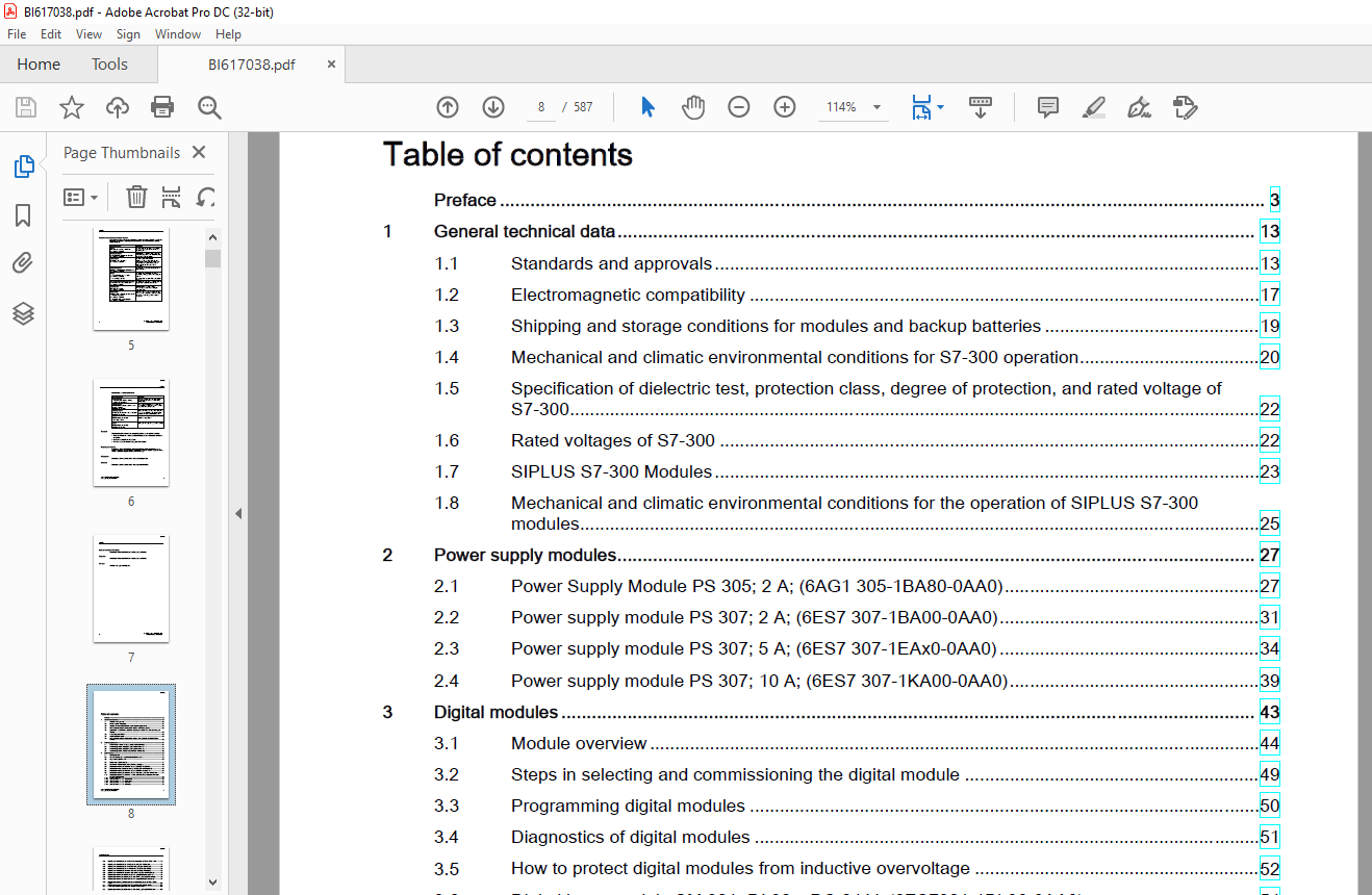
TABLE OF CONTENTS:
CAT Siemens S7-300 Automation System Module Data Operation & Maintenace Manual BI617038 – PDF DOWNLOAD
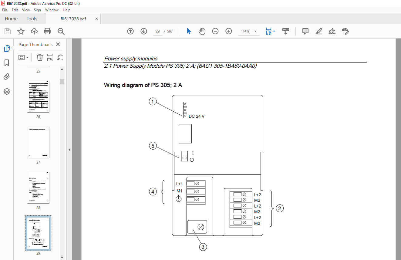
A5E00105505-05-EXT.pdf.....................................................................................................  0
	S7-300 Automation System Module Data...................................................................................  2
	Safety Guidelines......................................................................................................  3
	Preface................................................................................................................  4
	Table of contents......................................................................................................  8
	1 General technical data............................................................................................... 14
		1.1 Standards and approvals........................................................................................ 14
		1.2 Electromagnetic compatibility.................................................................................. 18
		1.3 Shipping and storage conditions for modules and backup batteries............................................... 20
		1.4 Mechanical and climatic environmental conditions for S7-300 operation.......................................... 21
		1.5 Specification of dielectric tests, protection class, degree of protection, and rated voltage of S7-300......... 23
		1.6 Rated voltages of S7-300....................................................................................... 23
		1.7 SIPLUS S7-300 Modules.......................................................................................... 24
		1.8 Mechanical and climatic environmental conditions for the operation of SIPLUS S7-300 modules.................... 26
	2 Power supply modules................................................................................................. 28
		2.1 Power Supply Module PS 305; 2 A; (6AG1 305-1BA80-0AA0)......................................................... 28
		2.2 Power supply module PS 307; 2 A; (6ES7 307-1BA00-0AA0)......................................................... 32
		2.3 Power supply module PS 307; 5 A; (6ES7 307-1EAx0-0AA0)......................................................... 35
		2.4 Power supply module PS 307; 10 A; (6ES7 307-1KA00-0AA0)........................................................ 40
	3 Digital modules...................................................................................................... 44
		3.1 Module overview................................................................................................ 45
		3.2 Steps in selecting and commissioning the digital module........................................................ 50
		3.3 Programming digital modules.................................................................................... 51
		3.4 Diagnostics of digital modules................................................................................. 52
		3.5 How to protect digital modules from inductive overvoltage...................................................... 53
		3.6 Digital input module SM 321; DI 32 x DC 24 V; (6ES7321 1BL00 0AA0)............................................. 55
		3.7 Digital output module SM 321; DI 32 x AC 120 V; (6ES7321 1EL00 0AA0)........................................... 57
		3.8 Digital input module SM 321; DI 16 x DC 24 V; (6ES7321 1BH02 0AA0)............................................. 60
		3.9 Digital input module SM 321; DI 16 x DC 24 V High Speed; (6ES7321 1BH10-0AA0).................................. 62
		3.10 Digital input module SM 321; DI 16 x 24 VDC; with hardware and diagnostics interrupts (6ES7321-7BH01-0AB0).... 64
			3.10.1 Isochronous mode........................................................................................ 68
			3.10.2 SM 321; DI 16 x DC 24 V - Parameters.................................................................... 70
			3.10.3 SM 321; DI 16 x DC 24 V - Diagnostics................................................................... 72
			3.10.4 SM 321; DI 16 x DC 24 V - Behavior...................................................................... 73
			3.10.5 SM 321; DI 16 x DC 24 V - Interrupts.................................................................... 74
		3.11 Digital input module SM 321; DI 16 x DC 24 V; source input; (6ES7321-1BH50-0AA0).............................. 77
		3.12 Digital input module SM 321; DI 16 x UC 24/48 V (6ES7321 1CH00 0AA0).......................................... 79
		3.13 Digital input module SM 321; DI 16 x DC 48-125 V; (6ES7321 1CH20 0AA0)........................................ 81
		3.14 Digital input module SM 321; DI 16 x 120/230 VAC (6ES7321 1FH00 0AA0)......................................... 84
		3.15 Digital input module SM 321; DI 8 x AC 120/230 V; (6ES7321 1FF01 0AA0)........................................ 86
		3.16 Digital input module SM 321; DI 8 x AC 120/230 V ISOL (6ES7321 1FF10-0AA0).................................... 89
		3.17 Digital output module SM 322; DO 32 x DC 24 V/ 0,5 A; (6ES7322 1BL00-0AA0).................................... 91
		3.18 Digital output module SM 322; DO 32 x AC 120/230 V/1 A; (6ES7322 1FL00-0AA0).................................. 94
		3.19 Digital output module SM 322; DO 16 x DC 24 V/ 0,5 A; (6ES7322 1BH01-0AA0).................................... 98
		3.20 Digital output module SM 322; DO 16 x DC 24 V/0,5 A High Speed; (6ES7322-1BH10-0AA0)..........................101
		3.21 Digital output module SM 322; DO 16 x UC 24/48 V; (6ES7322 5GH00-0AB0)........................................104
			3.21.1 Parameters of digital output module SM 322 DO 16 x UC24/48 V............................................107
		3.22 Digital output module SM 322; DO 16 x AC 120/230 V/1 A; (6ES7322 1FH00-0AA0)..................................110
		3.23 Digital output module SM 322; DO 8 x DC 24 V/2 A; (6ES7322 1BF01 0AA0)........................................113
		3.24 Digital output module SM 322; DO 8 x DC 24 V/ 0.5 A; with diagnostics interrupt; (6ES7322-8BF00-0AB0).........116
			3.24.1 SM 322; DO 8 x DC 24 V/0.5 A - Parameters...............................................................121
			3.24.2 SM 322; DO 8 x DC 24 V/0.5 A - Diagnostics..............................................................122
			3.24.3 SM 322; DO 8 x DC 24 V/0.5 A - Behavior.................................................................124
			3.24.4 SM 322; DO 8 x DC 24 V/0.5 A - Interrupts...............................................................124
		3.25 Digital output module SM 322; DO 8 x DC 48-125 V/1,5 A; (6ES7322 1CF00-0AA0)..................................125
		3.26 Digital output module SM 322;DO 8 x AC 120/230 V/2 A; (6ES7322 1FF01-0AA0)....................................129
		3.27 Digital output module SM 322; DO 8 x AC 120/230 V/2 A ISOL (6ES7322-5FF00-0AB0)...............................133
			3.27.1 Parameters of SM 322; DO 8 x AC 120/230 V/2 A ISOL......................................................136
			3.27.2 SM 322; DO 8 x AC 120/230 V/2 A ISOL - Diagnostics......................................................137
			3.27.3 SM 322; DO 8 x AC 120/230 V/2 A ISOL - Interrupts.......................................................137
		3.28 Relay output module SM 322; DO 16 x Rel. AC 120/230 V; (6ES7322 1HH01-0AA0)...................................138
		3.29 Relay output module SM 322; DO 8 x Rel. AC 230 V; (6ES7322 1HF01-0AA0)........................................142
		3.30 Relay output module SM 322; DO 8 x Rel. AC 230V/5A; (6ES7322 5HF00-0AB0)......................................146
			3.30.1 Parameters of SM 322; DO 8 x Rel. AC 230V/5A............................................................151
			3.30.2 SM 322; DO 8 x Rel. AC 230V/5A - Diagnostics............................................................152
			3.30.3 SM 322; DO 8 x Rel. AC 230V/5A - Interrupts.............................................................152
		3.31 Relay output module SM 322; DO 8 x Rel. AC 230 V/5 A; (6ES7322 1HF10-0AA0)....................................153
		3.32 Digital IO module SM 323; DI 16/DO 16 x DC 24 V/0.5 A; (6ES7323 1BL00-0AA0)...................................158
		3.33 Digital IO module SM 323; DI 8/DO 8 x DC 24 V/0.5 A; (6ES7323 1BH01-0AA0).....................................162
		3.34 Programmable digital IO module SM 327; DI 8/DO 8 x DC 24 V/0.5 A (6ES7327-1BH00-0AB0).........................166
			3.34.1 SM 327; DI 8/DX 8 x DC 24 V/0.5 A - Parameters..........................................................170
				3.34.1.1 Structure of data record 1 of SM 327; DI 8/DO 8 x DC 24 V/0.5 A...................................171
	4 Principles of analog value processing................................................................................174
		4.1 Overview.......................................................................................................174
		4.2 Wiring and connecting transducers to analog inputs.............................................................174
			4.2.1 Wiring and connecting electrically isolated transducers..................................................176
			4.2.2 Wiring non-isolated transducers..........................................................................178
		4.3 Wiring and connecting voltage transducers......................................................................180
		4.4 Wiring and connecting current transducers......................................................................181
		4.5 Wiring and connecting resistance thermometers and resistors....................................................182
		4.6 Wiring and connecting thermocouples............................................................................185
			4.6.1 Wiring and connecting thermocouples with internal compensation...........................................188
			4.6.2 Wiring and connecting thermocouples with external compensation...........................................188
		4.7 Wiring and connecting loads/actuators to analog outputs........................................................191
			4.7.1 Wiring and connecting loads/actuators to voltage outputs.................................................193
			4.7.2 Wiring and connecting loads/actuators to current outputs.................................................195
	5 Representation of the analog values of analog modules................................................................196
		5.1 Representation of the values for analog input channels.........................................................197
		5.2 Representation of analog values for analog output channels.....................................................213
		5.3 Setting the measuring method and ranges of analog input channels...............................................216
		5.4 Response of the analog modules.................................................................................218
			5.4.1 Influence of the power supply and operating state........................................................219
			5.4.2 Influence of the range of analog values..................................................................220
			5.4.3 Influence of the operational and basic error limits......................................................221
		5.5 Conversion / cycle time of analog modules......................................................................222
		5.6 Settling and response times of analog output channels..........................................................225
		5.7 Programming analog modules.....................................................................................226
			5.7.1 Parameters of analog input modules.......................................................................226
		5.8 Diagnostics of analog modules..................................................................................227
			5.8.1 Diagnostics messages of analog input modules.............................................................228
			5.8.2 Diagnostics messages of analog output modules............................................................228
			5.8.3 Causes of error and troubleshooting at analog input modules..............................................229
			5.8.4 Causes of error and troubleshooting at analog output modules.............................................229
		5.9 Interrupts of analog modules...................................................................................230
	6 Analog modules.......................................................................................................232
		6.1 Analog module selection and commissioning sequence.............................................................233
		6.2 Module overview................................................................................................234
			6.2.1 Analog input modules.....................................................................................234
			6.2.2 Analog output modules....................................................................................237
			6.2.3 Analog I/O modules.......................................................................................238
		6.3 Analog input module SM 331; AI 8 x 16 Bit; (6ES7331-7NF00-0AB0)................................................239
			6.3.1 Measurement types and ranges.............................................................................244
			6.3.2 Programmable parameters..................................................................................245
			6.3.3 Additional information on SM 331; AI 8 x 16 Bit..........................................................246
		6.4 Analog input module SM 331; AI 8 x 16 Bit; (6ES7331-7NF10-0AB0)................................................248
			6.4.1 Measurement types and ranges.............................................................................253
			6.4.2 Programmable parameters..................................................................................254
			6.4.3 Additional information for SM 331; AI 8 x 16 Bit.........................................................255
		6.5 Analog input module SM 331; AI 8 x 14 Bit High Speed; isochrone; (6ES7331-7HF0x-0AB0)..........................259
			6.5.1 Measurement types and ranges.............................................................................264
			6.5.2 Programmable parameters..................................................................................265
			6.5.3 Isochronous mode.........................................................................................266
			6.5.4 Additional information on SM 331; AI 8 x 14 Bit High Speed, isochrone....................................269
		6.6 Analog input module SM 331; AI 8 x 13 Bit; (6ES7 331-1KF01-0AB0)...............................................270
			6.6.1 Measurement types and ranges.............................................................................278
			6.6.2 Programmable parameters..................................................................................279
			6.6.3 Additional information on SM 331; AI 8 x 13 Bit..........................................................280
		6.7 Analog input module SM 331; AI 8 x 12 bit; (6ES7 331-7KF02-0AB0)...............................................280
			6.7.1 Measurement types and ranges.............................................................................288
			6.7.2 Programmable parameters..................................................................................291
			6.7.3 Additional information on SM 331; AI 8 x 12 Bit..........................................................292
		6.8 Analog input module SM 331; AI 2 x 12 Bit; (6ES7331-7KB02-0AB0)................................................293
			6.8.1 Measurement types and ranges.............................................................................301
			6.8.2 Programmable parameters..................................................................................303
			6.8.3 Additional information on SM 331; AI 2 x 12 Bit..........................................................304
		6.9 Analog input module SM 331; AI 8 x RTD; (6ES7331-7PF01-0AB0)...................................................305
			6.9.1 Measurement types and ranges.............................................................................310
			6.9.2 Programmable parameters..................................................................................311
			6.9.3 Additional information on SM 331; AI 8 x RTD.............................................................313
		6.10 Analog input module SM 331; AI 8 x TC; (6ES7331-7PF11-0AB0)...................................................317
			6.10.1 Measurement types and ranges............................................................................325
			6.10.2 Programmable parameters.................................................................................326
			6.10.3 Additional information on SM 331; AI 8 x TC.............................................................328
		6.11 Analog output module SM 332; AO 8 x 12 Bit; (6ES7332-5HF00-0AB0)..............................................332
			6.11.1 SM 332; AO 8 x 12 Bit - Output ranges...................................................................337
			6.11.2 Programmable parameters.................................................................................338
			6.11.3 Additional information on SM 332; AO 8 x 12 Bit.........................................................339
		6.12 Analog output module SM 332; AO 4 x 16 bit; isochrone; (6ES7332 7ND02-0AB0)...................................339
			6.12.1 SM 332; AO 4 x 16 Bit - Output ranges...................................................................344
			6.12.2 Programmable parameters.................................................................................345
			6.12.3 Isochronous mode........................................................................................346
			6.12.4 Additional information on SM 332; AO 4 x 16 Bit.........................................................347
		6.13 Analog output module SM 332; AO 4 x 12 Bit; (6ES7332 5HD01 0AB0)..............................................348
			6.13.1 Output ranges of SM 332; AO 4 x 12 Bit..................................................................353
			6.13.2 Programmable parameters.................................................................................353
			6.13.3 Additional information on SM 332; AO 4 x 12 Bit.........................................................354
		6.14 Analog output module SM 332; AO 2 x 12 Bit; (6ES7332 5HB01 0AB0)..............................................355
			6.14.1 Output ranges of SM 332; AO 2 x 12 Bit..................................................................360
			6.14.2 Programmable parameters.................................................................................360
			6.14.3 Additional information on SM 332; AO 2 x 12 Bit.........................................................361
		6.15 Analog IO module SM 334; AI 4/AO 2 x 8/8 Bit; (6ES7334 0CE01 0AA0)............................................362
			6.15.1 SM 334; AI 4/AO 2 x 8/8 Bit - Function principle........................................................368
			6.15.2 Measurement and output type of SM 334; AI 4/AO 2 x 8/8 bit..............................................369
			6.15.3 Measurement and output ranges of SM 334; AI 4/ AO 2 x 8/8 bit...........................................369
			6.15.4 Additional information on SM 334; AI 4/AO2 x 8/8 Bit....................................................370
		6.16 Analog IO module SM 334; AI 4/AO 2 x 12 bit; (6ES7334 0KE00 0AB0).............................................370
			6.16.1 Programmable parameters.................................................................................375
			6.16.2 Measurement types and ranges............................................................................376
			6.16.3 Additional information on SM 334; AI 4/ AO 2 x 12 bit...................................................377
	7 Other signal modules.................................................................................................378
		7.1 Module overview................................................................................................378
		7.2 Simulator module SM 374; IN/OUT 16; (6ES7 374-2XH01-0AA0)......................................................379
		7.3 Dummy module DM 370; (6ES7 370-0AA01-0AA0).....................................................................381
		7.4 Position detection module SM 338; POS-INPUT; (6ES7 338 4BC01 0AB0).............................................384
			7.4.1 Isochronous mode.........................................................................................388
			7.4.2 Functions of SM 338; POS-INPUT; encoder value acquisition................................................389
				7.4.2.1 Gray code/binary code converter....................................................................389
				7.4.2.2 Transferred encoder value and scaling..............................................................390
				7.4.2.3 Freeze function....................................................................................391
			7.4.3 Programming SM 338 POS-INPUT.............................................................................392
			7.4.4 Addressing SM 338 POS-INPUT..............................................................................393
			7.4.5 SM 338; POS-INPUT - Diagnostics..........................................................................395
			7.4.6 SM 338; POS INPUT - Interrupts...........................................................................397
	8 Interface modules....................................................................................................400
		8.1 Module overview................................................................................................400
		8.2 Interface module IM 360; (6ES7 360-3AA01-0AA0).................................................................401
		8.3 Interface module IM 361; (6ES7 361-3CA01-0AA0).................................................................403
		8.4 Interface module IM 365; (6ES7 365-0BA01-0AA0).................................................................405
	9 RS 485 Repeater......................................................................................................408
		9.1 Fields of application and properties; (6ES7 972-0AA01-0XA0)....................................................409
		9.2 Design of the RS 485 Repeater; (6ES7 972-0AA01-0XA0)...........................................................410
		9.3 RS 485 Repeater operation in ungrounded and grounded mode......................................................411
		9.4 Technical data.................................................................................................413
	A Parameter sets of signal modules.....................................................................................416
		A.1 Principles of programming signal modules in the user program...................................................416
		A.2 Parameters of digital IO modules...............................................................................417
		A.3 Parameters of digital output modules...........................................................................419
		A.4 Parameters of analog input modules.............................................................................421
		A.5 Parameters of analog input module SM 331; AI 8 x RTD...........................................................425
		A.6 Parameters of SM 331; AI 8 TC..................................................................................434
		A.7 Parameters of analog input module SM 331; AI 8 x 13 Bit........................................................442
		A.8 Parameters of analog input module SM 331; AI 8 x 16 Bit........................................................445
		A.9 Parameters of analog output modules............................................................................452
		A.10 Parameters of analog output module SM 332; AO 8 x 12 Bit......................................................454
		A.11 Parameters of analog IO modules...............................................................................456
	B Diagnostics data of signal modules...................................................................................460
		B.1 Evaluating diagnostic data of signal modules in the user program...............................................460
		B.2 Structure and content of diagnostics data bytes 0 to 7.........................................................461
		B.3 Channel-specific diagnostics data, starting at byte 8..........................................................464
		B.4 Diagnostics data of SM 338; POS-INPUT..........................................................................466
	C Dimensional drawings.................................................................................................468
		C.1 Dimensional drawings of the mounting rails.....................................................................469
			C.1.1 Bus modules..............................................................................................474
		C.2 Dimensional drawings of the power supply modules...............................................................475
		C.3 Dimensional drawings of the interface modules..................................................................478
		C.4 Dimensional drawings of the signal modules.....................................................................480
		C.5 Dimensional drawings of accessories............................................................................481
	E Directive on handling Electrostatic-Sensitive Devices (ESD)..........................................................484
		E.1 Definition of ESD..............................................................................................484
		E.2 Electrostatic charge of the body...............................................................................485
		E.3 Basic protective measures against electrostatic discharge......................................................486
	F Support & Service....................................................................................................  0
	G List of abbreviations................................................................................................488
		G.1 List of abbreviations..........................................................................................488
	Glossary...............................................................................................................490
	 Index.................................................................................................................500
		2..................................................................................................................500
		3..................................................................................................................500
		4..................................................................................................................500
		A..................................................................................................................500
		B..................................................................................................................501
		C..................................................................................................................501
		D..................................................................................................................502
		E..................................................................................................................503
		F..................................................................................................................503
		G..................................................................................................................503
		H..................................................................................................................503
		I..................................................................................................................503
		L..................................................................................................................504
		M..................................................................................................................504
		N..................................................................................................................504
		O..................................................................................................................504
		P..................................................................................................................505
		R..................................................................................................................506
		S..................................................................................................................507
		T..................................................................................................................510
		U..................................................................................................................510
		V..................................................................................................................510
		W..................................................................................................................510
	Product Information A5E00201782-03.....................................................................................512
		Title..............................................................................................................512
			Introduction...................................................................................................512
			Reparameterization steps in RUN mode...........................................................................513
			Notes on the table.............................................................................................514
	Product Information A5E0035293-03......................................................................................518
		Title..............................................................................................................518
		Einsatz der Baugruppen/Module im explosionsgefährdetenBereich Zone 2...............................................519
		Use of subassemblies/modules in a Zone 2 HazardousArea.............................................................522
		Utilisation des modules / coupleurs dans la zone àrisque d'explosion 2.............................................525
		Aplicación de los módulos / tarjetas en áreas conpeligro de explosión, zona 2......................................528
		Impiego di unità/moduli nell'area a pericolo diesplosione zona 2...................................................531
		Gebruik van de componenten/modulen in het explosiefgebied zone 2...................................................534
		Brug af komponenter/moduler i det eksplosionsfarligeområde zone 2..................................................537
		Rakenneryhmien/moduulien käyttöräjähdysvaarannetuilla alueilla, vyöhyke 2..........................................540
		Användning av komponentgrupperna/modulerna iexplosionsriskområde zon 2.............................................543
		Uso de grupos construtivos/módulos em área expostaao perigo de explosão 2..........................................546
		Χρήση των δομικών συγκροτημάτων/μονάδων σεεπικίνδυνη για έκρηξη περιοχή, ζώνη 2....................................549
		Použití konstrukčních skupin / modulů v prostředís nebezpečím výbuchu Zóna 2.......................................552
		Sõlmede/moodulite kasutamine plahvatusohtlikupiirkonna tsoonis 2...................................................555
		Ierīču/moduļu pielietojums sprādzienbīstamasteritorijas zonā 2.....................................................558
		Konstrukcinių grupių / modulių panaudojimassprogioje 2 zonos aplinkoje.............................................561
		A főegységek/modulok alkalmazása a 2. zónarobbanásveszélyes környezetben...........................................564
		Tqegħid tal-Komponenti / Modules fiż-Żona 2, fejnhemm Riskju ta' Splużjoni.........................................567
		Zastosowanie grup konstrukcyjnych / modułów w 2strefie zagrożenia wybuchem.........................................570
		Použitie konštrukčných skupín / modulov v prostredí snebezpečenstvom výbuchu zóny 2................................573
		Uporaba sklopov/modulov v eksplozivno ogroženemobmočju cone 2......................................................576
		Patlama tehlikesi olan Alan 2 bölgesinde ünitegruplarının/modüllerin kullanılması..................................579
		Използване на електронни блокове/модули въввзривоопасната област Зона 2............................................582
		Utilizarea unităţilor constructive/modulelor în domeniulcu potenţial exploziv din zona 2...........................585
VIDEO PREVIEW OF THE MANUAL:
S.V


