

Buell Xb9r Xb12r Firebolt 2004 Factory Service Repair Manual
FILE DETAILS:
LANGUAGE:ENGLISH
PAGES:500+
DOWNLOADABLE:YES
FILE TYPE:PDF
VIDEO PREVIEW OF THE MANUAL:

IMAGES PREVIEW OF THE MANUAL:
SAMPLE PAGE:
Buell Xb9r Xb12r Firebolt 2004 Factory Service Repair Manual
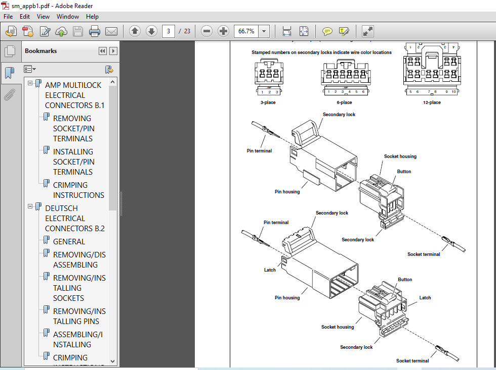
- Deutsch Connectors feature a superior seal to protect electrical contacts from dirt and moisture in harsh environments. The connector also provides superior pin retention. See Figure B-8. This 12-pin connector illustrates the various parts of the Deutsch connector. The following instructions may be followed for all 2-pin through 12-pin Deutsch connectors. Socket housing: alignment tabs and/or external latch, secondary locking wedge, internal seal, wire seal, seal pin.
- NOTE Seal pins or plugs are installed in the wire seals of unused pin and socket locations. If removed, seal pins must be replaced to maintain the integrity of the environmental seal. Pin housing: alignment grooves and/or external latch cover, attachment clip, secondary locking wedge, wire seal, seal pin. REMOVING/DISASSEMBLING Attachment clips are attached to the pin housings of most connectors.
- The clips are then attached to T-studs on the motorcycle frame. T-studs give positive location to electrical connectors and wire harness. Consistent location reduces electrical problems and improves serviceability. 1. Push the connector to disengage small end of slot on attachment clip from T-stud. Lift connector off T-stud. 2. Depress the external latch(es) on the socket housing side and use a rocking motion to separate the pin and socket halves. Two-, three-, four- and six-pin Deutsch connectors have one external latch, while eight- and twelve-pin connectors have two, both of which must be pressed simultaneously to separate the connector halves.
TABLE OF CONTENTS:
Buell Xb9r Xb12r Firebolt 2004 Factory Service Repair Manual
11 General 1-1
12 Fuel and Oil 1-5
13 Maintenance Schedule 1-6
14 Care of Molded-in-Color Body Panels 1-7
15 Battery Maintenance1-8
16 Engine Lubrication System 1-11
17 Brake System Maintenance 1-14
18 Tires and Wheels1-22
19 Clutch 1-23
110 Drive Belt Maintenance1-26
111 Primary Chain 1-29
112 Suspension Damping Adjustments1-31
113 Steering Head Bearings 1-35
114 Spark Plugs1-36
115 Air Cleaner Filter 1-38
116 Throttle Cable and Idle Speed Adjustment1-40
117 Interactive Exhaust Cable Adjustment 1-41
118 Ignition Timing 1-43
119 Headlights 1-45
120 Throttle Position Sensor (TPS)1-47
121 Storage1-48
122 Troubleshooting1-49
MAINTENANCE 1
21 Specifications2-1
22 Tire Specifications 2-4
23 Vehicle Identification Number2-5
24 Wheels 2-6
25 Front Wheel 2-8
26 Rear Wheel 2-15
27 Checking Cast Rim Runout 2-19
28 Tires 2-20
29 Brake Pedal 2-24
210 Front Brake Master Cylinder and Hand Lever 2-25
211 Front Brake Line2-29
212 Front Brake Caliper 2-31
213 Rear Brake Master Cylinder2-34
214 Rear Brake Line2-38
215 Rear Brake Caliper 2-40
216 Front Fork 2-43
217 Fork Clamps, Upper and Lower2-51
218 Steering Head Bearings2-53
219 Swingarm and Brace 2-55
220 Front and Rear Isolator 2-59
221 Frame 2-60
222 Rear Shock Absorber 2-61
223 Throttle Control 2-63
224 Clutch Hand Lever 2-64
225 Headlight Assembly and Support Bracket 2-65
226 Front Modules 2-68
227 Handlebars 2-70
228 Mirrors 2-72
229 Exhaust System2-73
230 Footpeg, Heel Guard, and Mount 2-76
231 Sprocket Cover 2-78
232 Fenders 2-79
233 Belt Guards 2-80
234 Chin Fairing2-82
235 Intake Cover Assembly 2-83
236 Air Scoops 2-84
237 Tail Section 2-85
238 Center Tail Section 2-89
239 Right Tail Section 2-90
240 Front Windscreen 2-92
241 Seat2-93
242 Passenger Seat Lock 2-94
243 Sidestand 2-96
CHASSIS
31 Specifications 3-1
32 Engine 3-6
33 Engine Rotation for Service 3-8
34 Stripping Motorcycle for Engine Service3-19
35 Engine Installation 3-29
36 Cylinder Head 3-45
37 Cylinder and Piston 3-63
38 Lubrication System 3-73
39 Oil Hose Routing and Oil Reservoir 3-74
310 Oil Pressure Indicator Switch 3-75
311 Crankcase Breathing System 3-76
312 Oiling System 3-78
313 Oil Pump 3-79
314 Oil Filter Mount3-82
315 Hydraulic Lifters3-83
316 Gearcase Cover and Cam Gears 3-85
317 Crankcase 3-90
41 Specifications 4-1
42 Dynamic Digital Fuel Injection 4-3
43 Diagnostic Introduction 4-5
44 Checking For Trouble Codes4-6
45 Check Engine Lamp Diagnostics4-8
46 Breakout Box4-10
47 Wiggle Test 4-11
48 Initial Diagnostic Check 4-12
49 Check Engine Lamp Not Illuminated at Key ON4-17
410 Check Engine Lamp On Continuously 4-20
411 Engine Cranks But Will Not Start 4-23
412 No ECM Power4-29
413 Fuel Pressure Test4-32
414 Idle Speed Control 4-37
415 Misfire 4-38
416 Trouble Code 11 4-43
417 Trouble Code 13 4-47
418 Trouble Code 14 4-52
419 Trouble Code 15 4-56
420 Trouble Code 16 4-60
421 Trouble Code 21 4-64
422 Trouble Codes 23 and 32 4-67
423 Trouble Codes 24 and 25 4-71
424 Trouble Code 33 4-74
425 Trouble Code 35 4-77
426 Trouble Code 36 4-80
427 Trouble Code 44 4-84
428 Trouble Codes 52, 53, 54 and 55 4-88
429 Trouble Code 56 4-89
430 Electronic Control Module 4-93
431 Cam Position Sensor and Rotor 4-95
432 Ignition Coil4-99
433 Oxygen Sensor4-101
434 Engine Temperature Sensor 4-102
435 Bank Angle Sensor4-104
436 Intake Air Temperature Sensor4-105
437 Throttle Position Sensor 4-106
51 Specifications 5-1
52 Electric Starter System 5-2
53 Starting System Diagnosis 5-4
54 Starter Activation Circuits 5-8
55 Diagnostics/Troubleshooting5-9
56 Starter System Testing 5-11
57 Starter 5-12
58 Starter Solenoid 5-21
61 Specifications 6-1
62 Primary Cover 6-3
63 Clutch Release Mechanism 6-7
64 Clutch 6-9
65 Primary Chain 6-16
66 Drive Belt System 6-21
67 Transmission6-25
68 Case Disassembly For Transmission Removal 6-26
69 Transmission Disassembly 6-29
610 Transmission Assembly6-36
611 Main Drive Gear 6-38
612 Transmission Right Case Bearings6-41
613 Transmission Left Case Bearings 6-43
614 Transmission Installation 6-44
615 Shifter Shaft6-48
616 Transmission Sprocket6-49
Table
71 Specifications 7-1
72 Ignition System 7-3
73 Ignition/Headlight Key Switch 7-5
74 Spark Plug Cables 7-10
75 Starter Interlock 7-12
76 Interactive Exhaust System (XB12S) 7-19
77 Charging System7-23
78 Alternator7-30
79 Voltage Regulator 7-32
710 Battery Cables 7-33
711 Battery 7-35
712 Headlight 7-42
713 Tail Lamp 7-45
714 License Plate Lamp Assembly7-46
715 Turn Signals 7-47
716 Turn Signal Flasher7-50
717 Handlebar Switches7-51
718 Speedometer Sensor 7-54
719 Instrument Module 7-55
720 Speedometer Performance Check7-56
721 Horn7-61
722 Neutral Indicator Switch7-63
723 Main Fuse and Fuses 7-64
724 Main Wire Harness7-65
725 Interactive Exhaust Actuator Harness 7-72
726 Sprocket Cover Wiring 7
APPENDIX A-TOOLS A-1
APPENDIX B-WIRING B-1
APPENDIX C-METRIC CONVERSIONSC-1
APPENDIX D-HOSE AND WIRE ROUTINGD-1
PLEASE NOTE:
- This is the same manual used by the dealers to diagnose and troubleshoot your vehicle
- You will be directed to the download page as soon as the purchase is completed. The whole payment and downloading process will take anywhere between 2-5 minutes
- Need any other service / repair / parts manual, please feel free to contact [email protected] . We still have 50,000 manuals unlisted


