

Buell Xb12r Firebolt 2008 Factory Service Repair Manual
FILE DETAILS:
LANGUAGE:ENGLISH
PAGES:700+
DOWNLOADABLE:YES
FILE TYPE:PDF
VIDEO PREVIEW OF THE MANUAL:

IMAGES PREVIEW OF THE MANUAL:
DESCRIPTION:
Buell Xb12r Firebolt 2008 Factory Service Repair Manual
GENERAL
This Service Manual has been prepared with two purposes in mind. First, it will acquaint the user with the construction of the Buell product and assist in the performance of basic maintenance
and repair. Secondly, it will introduce to the professional Buell Technician the latest field-tested and factory-approved major repair methods. We sincerely believe that this Service Manual will make your association with Buell products more pleasant and profitable.
HOW TO USE YOUR SERVICE MANUAL
Refer to the table below for the content layout of this manual.
NO. CHAPTER
1 Maintenance
2 Chassis
3 Engine
4 Fuel System
5 Electric Starter
6 Drive/Transmission
7 Electrical
A Appendix A Connector Repair
B Appendix B Wiring
C Appendix C Conversions
D Appendix D Hose and Wire Routing
E Appendix E Active Intake (Japanese Models)
F Appendix F Glossary
Use the TABLE OF CONTENTS (which follows this FOREWORD) and the INDEX (at the back of this manual) to quickly locate subjects. Sections and topics in this manual are sequentially numbered for easy navigation.
Bearings Anti-friction bearings must be handled in a special way. To keep out dirt and abrasives, cover the bearings as soon as they are removed from the package. Wash bearings in a non-flammable cleaning solution. Knock out packed lubricant inside by tapping the bearing against a wooden block.Wash bearings again. Cover bearings with clean material after setting them down to dry. Never use compressed air to dry bearings.
- Coat bearings with clean oil. Wrap bearings in clean paper. When bearings are installed against shoulders, be sure that the chamfered side of the bearing always faces the shoulder. Lubricate bearings and all metal contact surfaces before pressing into place.
- Only apply pressure on the part of the bearing that makes direct contact with the mating part. Install bearings with numbered side facing out. Always use the proper tools and fixtures for removing and installing bearings. Bearings do not usually need to be removed.
- Only remove bearings if necessary. Bushings Do not remove a bushing unless damaged, excessively worn or loose in its bore. Press out bushings that must be replaced. When pressing or driving bushings, be sure to apply pressure in line with the bushing bore.
- Use a bearing/bushing driver or a bar with a smooth, flat end. Never use a hammer to drive bushings. Inspect the bushing and the mated part for oil holes. Be sure all oil holes are properly aligned.
TABLE OF CONTENTS:
Buell Xb12r Firebolt 2008 Factory Service Repair Manual
GENERAL
Servicing a New Motorcycle
Safe Operating Maintenance
Shop Practices
Repair Notes
Safety
Removing Parts
Cleaning
Disassembly and Assembly
Checking Torques on Fasteners with Lock Patches
Magnetic Parts Trays
Repair and Replacement Procedures
Hardware and Threaded Parts
Threadlocking Agents
Wiring, Hoses and Lines
Instruments and Gauges
Bearings
Bushings
Gaskets
Lip Type Seals
O Rings (Preformed Packings)
Gears
Shafts
Part Replacement
Exhaust System Leakage
Cleaning
Part Protection
Cleaning Process
Rust or Corrosion Removal
Bearings
Tool Safety
Air Tools
Wrenches
Pliers/Cutters/Pry bars
Hammers 4
Punches/Chisels 4
Screwdrivers 4
Ratchets and Handles 4
Sockets 4
Storage Units 4
FUEL AND OIL
Fuel 5
Gasoline Blends: Buell Models 5
Engine Lubrication 5
Winter Lubrication 6
MAINTENANCE SCHEDULE
General 7
4 BATTERY MAINTENANCE
General 9
Battery Disconnection and Removal 0
Cleaning and Inspection 0
Charging Battery 0
Safety Precautions 0
Using a Battery Charger 0
Battery Installation and Connection
Storage
5 ENGINE OIL AND FILTER
General
Engine Oil Level Check
Change Engine Oil and Filter
Drain Oil
Change Filter 4
Fill Engine With Oil 4
Clear Oil Cooler 4
Return to Service 5
6 BRAKE SYSTEM MAINTENANCE
General 6
Bleeding Brakes 6
Bleeding Front Brake 7
Bleeding Rear Brake 8
Brake Pedal Adjustment 8
Brake Pad Thickness 9
Brake Rotor Thickness 0
Brake Pad Replacement 0
Front Pad Removal 0
Front Pad Installation 0
Rear Pad Removal
Rear Pad Installation
7 TIRES AND WHEELS
Tire Inflation
Tire Wear
Wheel Bearings 4
8 CLUTCH/TRANSMISSION/PRIMARY
FLUID
Inspection 5
Transmission Fluid 5
Adjustment 6
9 DRIVE BELT MAINTENANCE
General 8
Inspection 8
Rear Sprocket 8
Drive Belt 8
Idler Pulley 8
Cleaning 8
0 PRIMARY CHAIN
Inspection
Adjustment
STEERING HEAD BEARINGS
General
Inspection
Determining Proper Resistance
SPARK PLUGS
Inspection
AIR CLEANER AND EXHAUST SYSTEM
Removal 5
Cleaning and Inspection 6
Installation 6
Exhaust System Leak Check 7
4 THROTTLE CABLE
Throttle Cable Adjustment 8
5 INTERACTIVE EXHAUST CABLE
Adjustment 9
III
TABLE OF CONTENTS
6 HEADLIGHT
Inspection 4
Adjustment: Firebolt 4
Adjustment: Lightning 4
Horizontal Alignment 4
Vertical Alignment 4
Adjustment: Ulysses/Lightning XB STT 4
Horizontal Alignment 4
Vertical Alignment 4
7 WINDSHIELD MAINTENANCE
General 44
8 STORAGE
General 45
Removal From Storage 45
9 TROUBLESHOOTING
General 46
Engine 46
Starter Motor Does Not Operate or Does Not Turn Engine
Over 46
Engine Turns Over But Does Not Start 46
Starts Hard 46
Starts But Runs Irregularly or Misses 46
Spark Plug Fouls Repeatedly 46
Pre Ignition or Detonation (Knocks or Pings) 47
Overheating 47
Valve Train Noise 47
Excessive Vibration 47
Check Engine Light Illuminates During Operation 47
Lubrication System 47
Oil Does Not Return To Oil Tank 47
Engine Uses Too Much Oil Or Smokes Excessively 47
Engine Leaks Oil From Cases, Push Rods, Hoses,
Etc 47
Low Oil Pressure 47
High Oil Pressure 47
Electrical System 48
Alternator Does Not Charge 48
Alternator Charge Rate Is Below Normal 48
Speedometer Operates Erratically 48
Transmission 48
Shifts Hard 48
Jumps Out Of Gear 48
Clutch Slips 48
Clutch Drags Or Does Not Release 48
Clutch Chatters 48
Clutch 48
Slips 48
Drags or Does Not Release 48
Chatters 48
Chassis 48
Irregular/Inadequate Brake Action 48
Handling Irregularities 48
Suspension 49
CHASSIS
SPECIFICATIONS
Firebolt
Lightning
Ulysses
VEHICLE IDENTIFICATION NUMBER
(V I N )
Vehicle Identification Number (V I N )
WHEELS
General 5
Troubleshooting 5
4 FRONT WHEEL
Removal 7
Disassembly 7
Bearing Removal 7
Front Rotor Removal 9
Cleaning and Inspection 9
Assembly 0
Bearing Installation 0
Front Rotor Installation
Installation
5 REAR WHEEL
Removal 5
Cleaning and Inspection 5
Disassembly 5
Assembly 7
Installation 7
6 TIRES
General 9
Specifications 9
Removal 0
Cleaning and Inspection
Installation
Checking Tire Lateral Runout
Checking Tire Radial Runout
Adjustment
Wheel Balancing
7 CHECKING CAST RIM RUNOUT
General 4
Rim Lateral Runout 4
Rim Radial Runout 4
8 FRONT BRAKE MASTER CYLINDER
AND HAND LEVER
Removal 5
Disassembly 5
Brake Hand Lever 5
Front Master Cylinder 6
Cleaning and Inspection 6
Assembly 6
Front Master Cylinder 6
Brake Hand Lever 6
Installation 7
9 FRONT BRAKE LINE
Removal 8
Installation 8
IV TABLE OF CONTENTS
TABLE OF CONTENTS
0 FRONT BRAKE CALIPER
Removal 0
Disassembly 0
Cleaning and Inspection 0
Assembly
Installation
BRAKE PEDAL
Removal
Installation
REAR BRAKE MASTER CYLINDER
Removal: Firebolt/Lightning 4
Removal: Ulysses 5
Disassembly 7
Cleaning and Inspection 7
Assembly 7
Installation: Firebolt/Lightning 8
Installation: Ulysses 8
REAR BRAKE LINE
Removal: Firebolt 40
Installation: Firebolt 40
Removal: Lightning 4
Installation: Lightning 4
Removal: Ulysses 4
Installation: Ulysses 4
4 REAR BRAKE CALIPER
Removal 45
Disassembly 45
Cleaning and Inspection 46
Assembly 46
Installation 46
5 FENDERS
Front Fender: XB R 48
Removal 48
Installation 48
Rear Fender: XB R 48
Removal 48
Installation 48
Front Fender: XB9SX/XB S/XB Scg 48
Removal 48
Installation 48
Rear Fender: XB9SX/XB S/XB Scg 48
Removal 48
Installation 48
Front Fender: XB STT 48
Removal 48
Installation 48
Rear Fender: XB Ss/XB STT/XB X 49
Removal 49
Installation 49
Front Fender: XB X 49
Removal Upper Front Fender 49
Removal Lower Front Fender 49
Installing Upper Front Fender 49
Installing Lower Front Fender 49
6 FRONT FORK: ALL MODELS EXCEPT
XB STT/XB X
General 50
Removal 50
Disassembly 5
Damper Rod Disassembly 5
Cleaning and Inspection 55
Assembly 55
Damper Rod Assembly 55
Fork Assembly 55
Installation 57
7 FRONT FORK: XB STT/XB X
General 58
Removal 58
Disassembly 58
Cleaning and Inspection 6
Assembly 6
Installation 64
8 FORK CLAMPS: UPPER AND LOWER
Removal Firebolt 65
Installation: Firebolt 65
Removal: Lightning/Ulysses 66
Installation: Lightning/Ulysses 66
9 STEERING HEAD BEARINGS
Removal 68
Installation 68
0 FRONT FORK SLIDER PROTECTORS:
XB STT
Replacement: XB STT 7
SWINGARM AND BRACE
General 7
Brace 7
Removal 7
Installation 7
Removal: Swingarm 7
Disassembly 7
Swingarm 7
Cleaning and Inspection 7
Assembly 74
Swingarm 74
Installation: Swingarm 74
FRONT AND REAR ISOLATORS
Front Isolator 76
Removal 76
Installation 76
Rear Isolator 76
FRAME PUCKS
Removal 77
Installation 77
4 FRAME
Removal 78
Installation 78
TABLE OF CONTENTS V
TABLE OF CONTENTS
5 REAR SHOCK ABSORBER
General 79
Removal: Firebolt 8
Removal: Lightning 8
Removal: Ulysses 8
Installation: Firebolt 8
Installation: Lightning 8
Installation: Ulysses 84
6 THROTTLE CONTROL
Removal and Disassembly 85
Cleaning and Inspection 86
Assembly and Installation 86
Throttle Cable Replacement 86
Removal 86
Installation 86
7 CLUTCH CONTROL
General 88
Removal and Disassembly 88
Clutch Cable 88
Assembly and Installation 9
Clutch Cable 9
8 HEADLAMP ASSEMBLY AND
SUPPORT BRACKET
Removal: Firebolt 9
Disassembly: Firebolt 9
Assembly: Firebolt 9
Installation: Firebolt 94
Removal: Lightning/Ulysses 95
Disassembly: Lightning/Ulysses 97
Assembly: Lightning/Ulysses 97
Installation: Lightning/Ulysses 98
9 FAIRING SUPPORT BRACKET:
FIREBOLT
Removal 99
Installation 99
0 DEFLECTORS: XB9SX/XB STT/XB X
Removal and Disassembly 0
Assembly and Installation 0
GRILLE: XB9SX/XB STT/XB X
General 0
Removal and Installation 0
FRONT MODULES:
LIGHTNING/ULYSSES
Removal 0
Installation 04
HANDLEBARS: FIREBOLT
General 05
Removal 05
Right Clip On 05
Left Clip On 05
Installation 05
Right Clip On 05
Left Clip On 05
4 HANDLEBARS: LIGHTNING/ULYSSES
Removal 06
Installation 06
5 MIRRORS
Removal 08
Installation 08
6 FOOTPEG, HEEL GUARD AND MOUNT:
FIREBOLT/LIGHTNING
Rider 09
Wear Peg Removal 09
Footpeg Removal 09
Heel Guard Removal 09
Mount Removal 09
Mount Installation 09
Heel Guard Installation 09
Footpeg Installation 09
Wear Peg Installation 09
Passenger 09
Footpeg Removal 09
Heel Guard Removal 09
Mount Removal 09
Mount Installation 0
Heel Guard Installation 0
Footpeg Installation 0
7 HEEL GUARD AND FOOTPEG
MOUNTS: ULYSSES
Rider Footpegs
Footpeg Removal
Footpeg Installation
Passenger Footpegs
Footpeg Removal
Footpeg Installation
Mount Removal
Mount Installation
Heel Guard Replacement
8 SPROCKET COVER
Removal
Installation
9 BELT GUARDS
Removal 4
Installation 4
40 INTAKE COVER
Removal 5
Installation 5
4 SUBFRAME TAIL ASSEMBLY AND
BODY WORK: FIREBOLT
Disassembly 7
Cleaning 0
Assembly 0
VI TABLE OF CONTENTS
TABLE OF CONTENTS
4 LEFT TAIL SECTION AND BATTERY
PAN: LIGHTNING
Disassembly
Cleaning
Assembly 4
4 CENTER TAIL SECTION: LIGHTNING
Disassembly 6
Assembly 6
44 RIGHT TAIL SECTION: LIGHTNING
Disassembly 7
Assembly 7
45 LEFT TAIL SECTION AND BATTERY
PAN: XB X
Disassembly 8
Cleaning 8
Assembly 9
46 CENTER TAIL LOOP: XB X
Disassembly
Assembly
47 RIGHT TAIL SECTION: XB X
Disassembly
Assembly 4
48 SIDESTAND
General 5
Removal 5
Disassembly 5
Assembly 5
Installation 6
49 FRONT FAIRING,WINDSHIELD, AND
MIRRORS: FIREBOLT
Removal 7
Installation 7
50 WINDSHIELD AND WINDSCREEN:
LIGHTNING AND ULYSSES
Removal: Lightning 8
Installation: Lightning 8
Removal: Ulysses 9
Installation: Ulysses 9
5 NUMBER PLATES: XB STT
General 40
Removal 40
Installation 4
5 AIR SCOOPS
Ram Air Scoop 4
Removal 4
Installation 4
Engine Shroud Air Scoop 4
Removal 4
Installation 4
Oil Cooler Air Scoop 4
Removal 4
Installation 4
5 CHIN FAIRING
Removal 44
Installation 44
54 SEAT
Firebolt 45
Rider Seat 45
Pillion 45
Lightning 45
Removal 45
Installation 46
Ulysses 47
Removal 47
Installation 47
55 SEAT LOCKS
Removal: Lightning 49
Installation: Lightning 49
Removal: XB X 50
Installation: XB X 50
Pillion Lock Removal: XB R 5
Pillion Lock Installation: XB R 5
56 TRIPLE TAIL: XB X
General 5
Removal 5
Disassembly 5
Assembly 5
Installation 54
ENGINE
SPECIFICATIONS
General
ENGINE
Adjustment/Testing 5
General 5
Compression Test 5
Cylinder Leakage Test 5
Diagnosing Smoking Engine or High Oil Consumption 6
ENGINE ROTATION FOR SERVICE
General 7
Disassembly 7
Assembly
4 ENGINE REMOVAL
Disassembly 5
5 ENGINE INSTALLATION
Assembly 5
Engine Preparation for Re installation 5
Installing Engine in Frame 6
TABLE OF CONTENTS VII
TABLE OF CONTENTS
6 CYLINDER HEAD
Removal 7
Rocker Box Assemblies 7
Cylinder Head Assemblies 8
Disassembly 9
Cleaning and Inspection 4
Cylinder Heads 4
Rocker Arm Assemblies 4
Valves 4
Valve Seats 4
Valve Guides 4
Valve Springs 44
Spark Plug Threads 44
Push Rods 44
Replacing Rocker Arm Bushings 44
Replacing Valve Guides 45
Procedure For Using The Neway Valve Seat Cutter 46
Assembly 47
Push Rod Cover Installation 48
Cylinder Head Installation 49
7 CYLINDER AND PISTON
Removal/Disassembly 5
Cleaning and Inspection 5
Checking Gasket Surface 54
Measuring Cylinder Bore 54
Deglazing Cylinder 55
Fitting Piston Rings 55
Connecting Rod Bushing 57
Assembly/Installation 58
8 LUBRICATION SYSTEM
Lubrication 6
9 OIL RESERVOIR AND OIL HOSE
ROUTING
General 6
0 OIL LINE FITTINGS
Removal 64
Installation 64
OIL COOLER
General 66
Removal 66
Installation 66
OIL PRESSURE INDICATOR SWITCH
General 67
Oil Pressure Signal Light 67
Oil Pressure 67
CRANKCASE BREATHING SYSTEM
General 69
Reed Valve Replacement 69
4 OILING SYSTEM
General 7
5 OIL PUMP
General 7
Removal/Disassembly 7
Cleaning and Inspection 75
Assembly/Installation 76
6 HYDRAULIC LIFTERS
General 78
Removal 78
Cleaning and Inspection 78
Installation 79
7 GEARCASE AND CAM GEARS
General 80
Removal and Disassembly 8
Cleaning and Inspection 8
Cam and Pinion Gear Identification, Inspection and
Selection 8
Assembly and Installation 8
8 CRANKCASE
General 84
Disassembly 84
Crankcase Halves 84
Oil Filter Adapter 85
Piston Jets 86
Removal 86
Installation 86
Removing Cylinder Base Studs 86
Flywheel Assembly 86
Pinion Shaft Bearing 89
General 89
Selection 90
Replacement 90
Lapping Pinion Shaft Bearing Outer Race 9
Checking Connecting Rod Side Play 9
Assembly 94
Crankcase Halves 94
FUEL SYSTEM
4 SPECIFICATIONS
General 4
4 AIR CLEANER ASSEMBLY
Removal 4
Inspection 4
Installation 4
4 ELECTRONIC CONTROL MODULE (ECM)
Removal: Firebolt 4 5
Installation: Firebolt 4 5
Removal: Lightning 4 5
Installation: Lightning 4 5
Removal: Ulysses 4 6
Installation: Ulysses 4 6
4 4 THROTTLE POSITION SENSOR (TPS)
Removal 4 8
Installation 4 8
VIII TABLE OF CONTENTS
TABLE OF CONTENTS
4 5 IGNITION COIL
Removal 4 9
Installation 4 9
4 6 OXYGEN SENSOR
General 4 0
Removal 4 0
Installation 4 0
4 7 ENGINE TEMPERATURE SENSOR (ET)
General 4
Removal 4
Installation 4
4 8 BANK ANGLE SENSOR (BAS)
General 4
Removal 4
Firebolt 4
Lightning 4
Ulysses 4
Installation 4 4
Firebolt 4 4
Lightning 4 4
Ulysses 4 5
4 9 INTAKE AIR TEMPERATURE SENSOR
(IAT)
General 4 6
Removal 4 6
Installation 4 6
4 0 COOLING FAN
General 4 7
Removal 4 7
Installation 4 7
4 FUEL TANK VENT VALVE
General 4 8
Removal 4 8
Installation 4 8
4 FUEL CAP RETAINING RING
Removal 4 9
Installation 4 9
4 FUEL PUMP
Draining Fuel Tank 4 0
Removal 4 0
Repair 4
Fuel Pressure Regulator Replacement 4
Low Fuel Level Sensor Replacement 4
Fuel Filter Replacement 4
Fuel Pump Wire Harness Replacement 4 5
Installation 4 6
4 4 THROTTLE BODY
General 4 8
Removal 4 8
Repair 4
Throttle Position Sensor 4
Fuel Injectors 4
Installation 4
Injector Leak Testing 4
4 5 INTAKE LEAK TEST
General 4
Leak Tester 4
Parts List 4
Tester Assembly 4
Tester Adjustment 4
Procedure 4
4 6 EXHAUST SYSTEM
Removal and Disassembly 4 5
Muffler 4 5
Front Muffler Mount 4 5
Rear Muffler Bracket 4 5
Exhaust Header 4 5
Assembly and Installation 4 6
Exhaust Header 4 6
Rear Muffler Bracket 4 7
Front Muffler Mount 4 7
Muffler and Straps 4 7
4 7 EVAPORATIVE EMISSIONS CONTROL
(CA MODELS)
General 4 9
Troubleshooting 4 9
Removal: Firebolt 4 9
Vent Valve 4 9
Canister 4 9
Removal: Lightning/Ulysses 4 9
Vent Valve 4 9
Canister 4 9
Installation: Firebolt 4 9
Vent Valve 4 9
Canister 4 9
Installation: Lightning/Ulysses 4 40
Vent Valve 4 40
Canister 4 40
Hose Routing 4 4
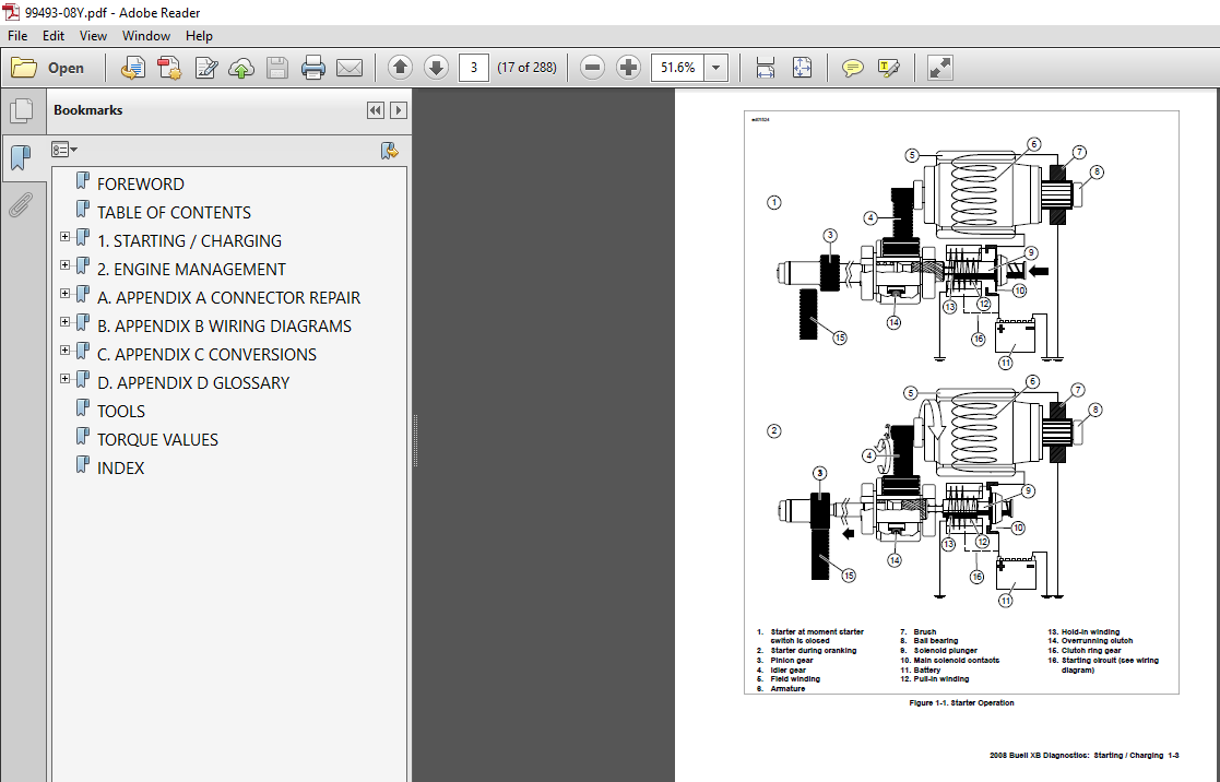
ELECTRIC STARTER
5 SPECIFICATIONS
General 5
5 STARTER
General 5
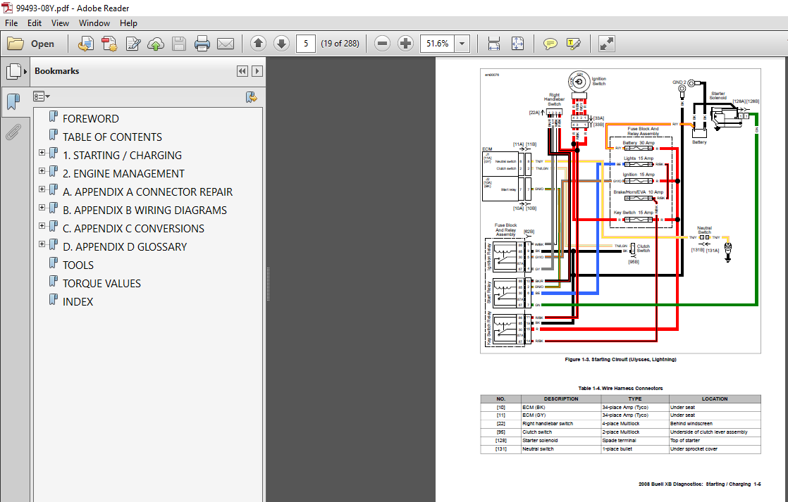
Starter Relay 5
Wiring Diagrams 5
Removal 5
Disassembly, Inspection, and Repair 5
Assembly 5 6
Installation 5 7
5 STARTER SOLENOID
Replacement 5 9
Disassembly 5 9
Assembly 5 9
TABLE OF CONTENTS IX
TABLE OF CONTENTS
DRIVE/TRANSMISSION
6 SPECIFICATIONS
General 6
6 PRIMARY COVER
Removal 6
Primary Chain Adjuster Replacement 6
Installation 6 4
6 CLUTCH RELEASE MECHANISM
Disassembly 6 6
Cleaning and Inspection 6 6
Assembly 6 7
6 4 CLUTCH
General 6 8
Removal 6 0
Clutch Pack Cleaning and Inspection 6
Adjusting Screw Disassembly/Assembly 6
Assembly and Installation 6
6 5 PRIMARY CHAIN
General 6 5
Removal 6 5
Clutch Shell/Hub Inspection 6 6
Clutch Shell Bearing Replacement 6 7
Installation 6 8
6 6 DRIVE BELT AND IDLER PULLEY
General 6
Drive Belt Removal 6
Drive Belt Installation 6
Idler Pulley Removal 6
Idler Pulley Installation 6
6 7 TRANSMISSION
General 6 5
6 8 CASE DISASSEMBLY FOR
TRANSMISSION REMOVAL
General 6 6
Right Crankcase Removal 6 6
6 9 TRANSMISSION DISASSEMBLY
Transmission Removal From Left Crankcase 6 9
Mainshaft/Countershaft 6
Mainshaft Disassembly 6
Cleaning and Inspection 6 4
Countershaft Disassembly 6 4
Cleaning and Inspection 6 4
6 0 TRANSMISSION ASSEMBLY
Mainshaft Assembly 6 6
Countershaft Assembly 6 6
6 MAIN DRIVE GEAR AND BEARING
General 6 8
Removal 6 8
Main Drive Gear Bearing 6 9
Disassembly 6 40
Assembly 6 40
Installation 6 4
Main Drive Gear Ball Bearing 6 4
Main Drive Gear 6 4
Main Drive Gear Seal 6 4
6 TRANSMISSION RIGHT CASE
BEARINGS
Removal 6 45
Countershaft Needle Bearing 6 45
Shifter Drum Bushing 6 45
Installation 6 45
Countershaft Needle Bearing 6 45
Shifter Drum Bushing 6 45
6 TRANSMISSION LEFT CASE
BEARINGS
Removal 6 47
Mainshaft and Countershaft Bearings 6 47
Shift Drum Bearing 6 47
Installation 6 47
Mainshaft and Countershaft Bearings 6 47
Shift Drum Bushing 6 47
6 4 TRANSMISSION INSTALLATION
Installation 6 48
Shifter Forks and Drum Assembly 6 49
Installing Right Crankcase 6 50
6 5 SHIFTER SHAFT
Installation 6 5
6 6 TRANSMISSION SPROCKET
Removal 6 54
Installation 6 55
ELECTRICAL
7 SPECIFICATIONS
General 7
7 IGNITION SYSTEM
General 7
Troubleshooting 7
7 IGNITION/HEADLAMP KEY SWITCH
General 7 5
Removal: Firebolt 7 5
Disassembly: Firebolt 7 6
Assembly: Firebolt 7 6
Installation: Firebolt 7 7
Removal: Lightning 7 7
Disassembly: Lightning 7 9
Assembly: Lightning 7 9
Installation: Lightning 7
Removal: Ulysses 7
Disassembly: Ulysses 7
Assembly: Ulysses 7
X TABLE OF CONTENTS
TABLE OF CONTENTS
Installation: Ulysses 7 4
7 4 SPARK PLUG CABLES
General 7 5
Removal 7 5
Inspection 7 5
Installation 7 5
7 5 CHARGING SYSTEM
General 7 7
Alternator 7 7
Voltage Regulator 7 7
7 6 BATTERY CABLES
Removal 7 9
Installation 7 9
7 7 VOLTAGE REGULATOR
General 7
Removal 7
Installation 7
7 8 ALTERNATOR
Removal and Disassembly 7
Rotor 7
Stator 7
Cleaning and Inspection 7 4
Assembly and Installation 7 4
7 9 HEATED HAND GRIPS: ULYSSES
Heated Hand Grips 7 5
Removal 7 5
Installation 7 5
7 0 HORN
Removal 7 8
Installation 7 8
Troubleshooting 7 9
7 TURN SIGNAL FLASHER
Removal 7 0
Installation 7 0
7 FRONT TURN SIGNALS
Bulbs 7
Repair 7
Connections and Wire Routing 7
Firebolt 7
Removal 7
Installation 7 5
Lightning 7
Removal 7
Installation 7
Ulysses 7
Removal 7
Installation 7 6
7 REAR TURN SIGNALS
Bulbs 7 5
Connections and Wire Routing 7 5
Firebolt 7 5
Removal 7 5
Installation 7 5
Lightning 7 6
Removal 7 6
Installation 7 6
Ulysses 7 7
Remove 7 7
Installation 7 7
7 4 INTERACTIVE EXHAUST SYSTEM
General 7 9
Removal 7 4
Installation 7 4
7 5 HEADLIGHT
General 7 4
Headlight Bulbs: Firebolt 7 4
Removal 7 4
Installation 7 4
Headlight Bulbs: Lightning and Ulysses 7 44
Removal 7 44
Installation 7 45
7 6 TAIL LAMP
Firebolt/Lighting 7 48
Removal 7 48
Installation 7 48
Ulysses 7 49
Removal 7 49
Installation 7 49
7 7 LICENSE PLATE LAMP ASSEMBLY
Lightning 7 50
Removal 7 50
Installation 7 50
Ulysses 7 50
Removal and Disassembly 7 50
Assembly and Installation 7 5
7 8 MAIN FUSE AND FUSES
General 7 5
Fuses 7 5
Main Fuse 7 5
7 9 NEUTRAL INDICATOR SWITCH
General 7 56
Testing 7 56
Removal and Installation 7 56
7 0 CRANKSHAFT POSITION SENSOR
(CKP)
GENERAL 7 57
REMOVAL 7 57
Installation 7 57
7 VEHICLE SPEED SENSOR (VSS)
Removal 7 59
Installation 7 59
TABLE OF CONTENTS XI
TABLE OF CONTENTS
7 INSTRUMENT MODULE
General 7 60
Removal 7 60
Bulb Replacement 7 60
Installation 7 6
7 MAIN WIRE HARNESS
General 7 6
Removal 7 6
Installation 7 70
7 4 INTERACTIVE EXHAUST HARNESS:
XB MODELS
Firebolt 7 78
Removal 7 78
Installation 7 78
Lightning 7 79
Removal 7 79
Installation 7 79
Ulysses 7 80
Removal 7 80
Installation 7 80
7 5 SPROCKET COVER WIRING
General 7 8
Removal 7 8
7 6 AUXILIARY POWER OUTLETS:
ULYSSES
General 7 8
Accessory Load Test 7 8
APPENDIX A CONNECTOR REPAIR
A AMP PLACE CONNECTORS
AMP Place Connector Repair A
General A
Separating Pin and Socket Housings A
Mating Pin and Socket Housings A
Removing Socket Terminals A
Installing Socket Terminal A
Removing Pin Terminal A
Installing Pin Terminal A
A AMP MULTILOCK CONNECTORS
AMP Multilock Connector Repair A
General A
Separating Pin and Socket Housings A
Mating Pin and Socket Housings A
Removing Terminals from Housing A
Inserting Terminals into Housing A 4
Preparing Wire Leads for Crimping A 4
Crimping Terminals to Leads A 5
Inspecting Crimped Terminals A 6
A AUTOFUSE ELECTRICAL
CONNECTORS
Autofuse Connector Repair A 7
General A 7
Disassembly A 7
Assembly A 7
A 4 DELPHI CONNECTORS
Delphi Connector Repair A 8
General A 8
Separating Pin and Socket Housings A 8
Mating Pin and Socket Housings A 8
Removing Socket Terminals A 8
Installing Socket Terminals A 8
A 5 DEUTSCH ELECTRICAL CONNECTORS
Deutsch Connector Repair A 0
General A 0
Separating Pin and Socket Housings A 0
Mating Pin and Socket Housings A 0
Removing Socket Terminals A 0
Installing Socket Terminals A 0
Removing Pin Terminals A
Installing Pin Terminals A
Crimping Terminals A
A 6 DEUTSCH STANDARD TERMINAL
REPAIR
Deutsch Standard Terminal Crimps A 4
Preparing Wire Leads for Crimping A 4
Crimping Terminal to Lead A 4
Inspecting Crimps A 4
A 7 DEUTSCH SOLID BARREL MINI
TERMINAL REPAIR
Deutsch Solid Barrel Terminal Crimps A 5
Preparing Wire Leads For Crimping A 5
Adjusting Crimper Tool A 5
Crimping a Barrel Contact To Wire Lead A 5
Inspecting Crimps A 5
A 8 DEUTSCH MINI TERMINAL REPAIR
Deutsch Mini Terminal Crimps A 7
Preparing Wire Leads for Crimping A 7
Crimping a Mini Terminal to Wire Lead A 7
Inspecting Crimps A 7
A 9 MOLEX CONNECTORS
Molex Connector Repair A 8
Separating Pin and Socket Housings A 8
Mating Pin and Socket Housings A 8
Removing Terminals A 8
Installing Terminals A 8
Crimp Terminal to Lead A 9
Prepare Lead A 9
Prepare Tool A 9
Position Terminal in the Punch/Die A 0
Insert Stripped Lead A 0
Crimp Terminal to Lead A 0
Inspect Crimp A
A 0 PACKARD 50 METRI PACK
CONNECTORS
50 Metri Pack Connector Repair A
XII TABLE OF CONTENTS
TABLE OF CONTENTS
General A
Separating Pin and Socket Housings A
Mating Pin and Socket Housings A
Removing Socket Terminal A
Inserting Socket Terminal A
A PACKARD 80 METRI PACK RELAY
AND FUSE BLOCK CONNECTORS
Fuse Block Repair A 4
Removing Socket Terminals A 4
Installing Socket Terminals A 4
Crimping Terminals A 4
A PACKARD 480 METRI PACK
CONNECTORS
480 Metri Pack Connector Repair A 5
General A 5
Separating Pin and Socket Housings A 5
Mating Pin and Socket Housings A 5
Removing Socket Terminals A 5
Installing Socket Terminals A 5
A PACKARD 6 0 METRI PACK
CONNECTORS
6 0 Metri Pack Connector Repair A 6
General A 6
Separating Pin and Socket Housings A 6
Mating Pin and Socket Housings A 6
Removing Socket Terminal A 6
Installing Socket Terminal A 6
A 4 PACKARD METRI PACK TERMINALS
Metri Pack Terminal Crimps A 7
Matching Terminal To Crimper A 7
Preparing Wire Lead A 7
Crimping Wire Core A 7
Crimping Insulation/Seal A 7
Inspecting Crimps A 8
A 5 PACKARD ECM CONNECTOR
Packard 00W Connector Repair A 9
General A 9
Separating Socket Housing From ECM A 9
Mating Socket Housing To ECM A 9
Removing Socket Terminal A 9
Installing Socket Terminal A 9
Crimping Terminals A 9
A 6 PACKARD MICRO 64 CONNECTORS
Packard Micro 64 Connector Repair A
General A
Separating Pin and Socket Housings A
Mating Pin and Socket Housings A
Removing Terminal A
Installing Terminal A
Preparing Wire Leads for Crimping A
Crimping Terminals A
Inspecting Crimps A
A 7 SEALED SPLICE CONNECTORS
Sealed Splice Connector Repair A 4
General A 4
Preparing Wire Leads A 4
Splicing Wire Leads A 4
Inspecting Seals A 4
APPENDIX B WIRING
B WIRING DIAGRAMS
Connector Locations B
Function/Location B
Place and Color B
Connector Number B
Repair Instructions B
Wiring Diagram Information B
Wire Color Codes B
Wiring Diagram Symbols B
008 Buell Wiring Diagrams B 4
APPENDIX C CONVERSIONS
C LENGTH CONVERSION
Conversion Table C
C FLUID CONVERSION
United States System C
Metric System C
British Imperial System C
C TORQUE CONVERSION
United States System C
Metric System C
APPENDIX D HOSE AND WIRE
ROUTING
D APPENDIX D: HOSE AND WIRE
ROUTING
Firebolt D
Lightning D
Ulysses D 5
APPENDIX E ACTIVE INTAKE
(JAPANESE MODELS)
E ACTIVE INTAKE SYSTEM (JAPANESE
MODELS ONLY)
General E
Active Intake System E
Diagnostic Notes E
Verify Settings E
WOT Check E
Cable E
Adjustment E
Throttle Stop Screw E
Removal E 4
TABLE OF CONTENTS XIII
TABLE OF CONTENTS
Installation E 5
APPENDIX F GLOSSARY
F GLOSSARY
Acronyms and Abbreviations F
REFERENCE MATERIAL
TOOLS I
TORQUE VALUES VII
INDEX XXV
XIV TABLE
PLEASE NOTE:
- This is the SAME exact manual used by your dealers to fix your vehicle.
- The same can be yours in the next 2-3 mins as you will be directed to the download page immediately after paying for the manual.
- Any queries / doubts regarding your purchase, please feel free to contact [email protected]


