

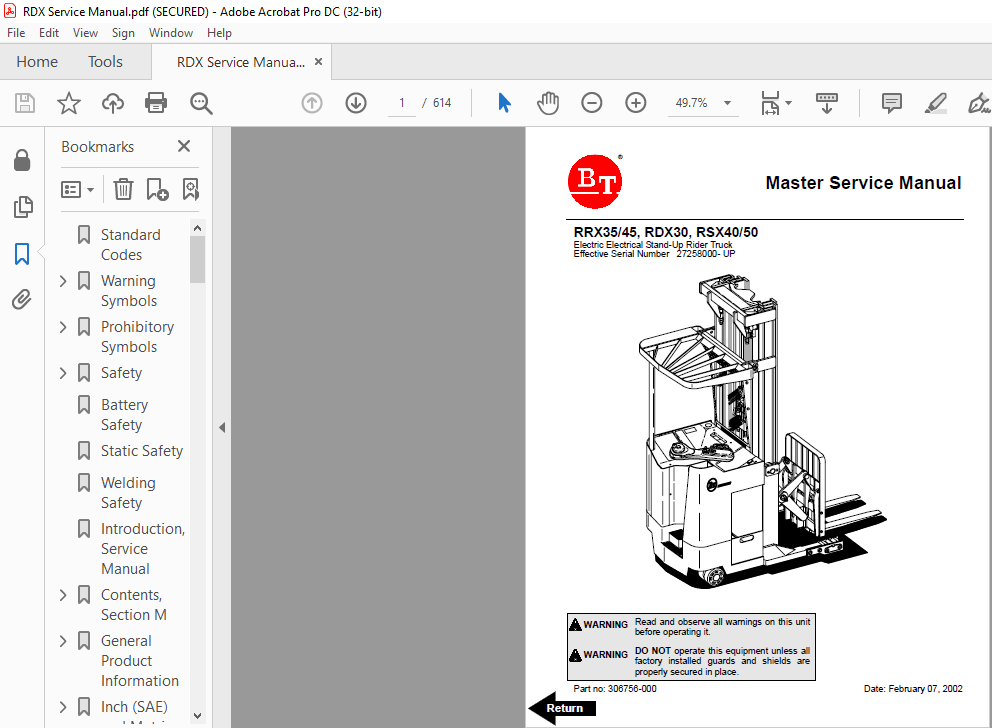
BT Electric Electrical Stand-Up Rider Truck RRX35/45 RDX30 RSX40/50 Master Service Manual 306756-000 – PDF DOWNLOAD
DESCRIPTION:
BT Electric Electrical Stand-Up Rider Truck RRX35/45 RDX30 RSX40/50 Master Service Manual 306756-000 – PDF DOWNLOAD
Introduction, Service Manual :
- The information in this Service Manual covers models RRX35, RRX45, RDX30, RSX40, and RSX50. Federal and State laws require that operators be completely trained in the safe operation of trucks in accordance with OSHA regulation 1910.178.
- An Operator’s Manual is sent with every BT Prime-Mover lift truck when it is manufactured. If the Operator’s Manual is missing from the truck.
- This Service Manual is not a training manual. The information contained in this service manual is intended as a guide to help trained, qualified, and authorized technicians safely service the truck.
- The Service Manual is divided into four separate sections, which cover needed information for servicing the truck types. The main subject for each of the sections are as described below.
SECTION SUBJECT
M MACHINE INFORMATION
P PLANNED MAINTENANCE
S SERVICE INSTRUCTIONS
O OPTIONS
TABLE OF CONTENTS:
BT Electric Electrical Stand-Up Rider Truck RRX35/45 RDX30 RSX40/50 Master Service Manual 306756-000 – PDF DOWNLOAD
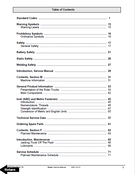
Standard Codes 3
Warning Symbols 17
1 Warning Levels 17
Prohibitory Symbols 18
1 Ordinance Symbols 18
Safety 19
1 General Safety 19
Battery Safety 23
Static Safety 28
Welding Safety 29
Introduction, Service Manual 31
Contents, Section M 33
1 Machine Information 33
General Product Information 35
1 Presentation of the Rider Trucks 35
1 1 Truck Side Views 35
1 2 Open Back Compartment 36
1 3 Intended Truck Application 36
1 4 Prohibited Truck Application 37
1 5 Truck Data 37
1 6 RRX35 Dimensions 38
1 7 RRX45 Dimensions 39
1 8 RDX30 Dimensions 40
1 9 RSX40 Dimensions 41
1 10 RSX50 Dimensions 42
1 11 Data Plate 43
2 Main Components 44
Inch (SAE) and Metric Fasteners 47
1 Introduction 47
2 Nomenclature, Threads 48
3 Strength Identification 49
4 Conversion of Metric and English Units 57
Technical Service Data 59
Ordering Spare Parts 63
Contents, Section P 65
1 Planned Maintenance 65
Introduction, Maintenance 67
1 Jacking Truck Off The Floor 68
1 1 Elevate Rear of Truck 68
1 2 Elevate Either Side of Truck 69
2 Lubricants 70
2 1 Standard 70
2 2 Corrosion 70
2 3 Cold Storage 70
2 4 Freezer Storage 72
Service Schedule 73
1 Planned Maintenance Schedule 73
2 Planned Maintenance Procedures 78
2 1 Services Performed Daily or Every 8 Operating Hours 78
2 1 1 Battery Discharge Indicator with slow down 78
2 1 2 Hydraulic System 78
2 1 3 Frame/Sheet Metal 79
2 1 4 Wheels/Tires 79
2 1 5 Functions/Operations 79
2 2 Services Performed Monthly or Every 120 Operating Hours 79
2 2 1 Inspection 79
2 2 2 Transmission 79
2 2 3 Brakes 79
2 2 4 Battery 80
2 2 5 Electrical Connections 80
2 2 6 Contactor Tips (NOT Sealed) 80
2 2 7 Motor Brushes 80
2 2 8 Drive Motor 80
2 2 9 Hydraulic Reservoir 81
2 2 10 Frame Lube 81
2 2 11 Pivot Points 81
2 3 Services Performed Every 480 or 960 Operating Hours 82
2 3 1 Drive Motor 82
2 4 Services Performed Annually or Every 1440 Operating Hours 83
2 4 1 Inspection 83
2 4 2 Transmission 83
2 4 3 Battery 83
2 4 4 Hydraulic System 84
2 4 5 Brakes 84
2 4 6 Lift and Carriage Chains 84
Lubrication Chart 85
Oil and Grease Specifications 86
1 Approved Oils and Grease 86
2 Grease Location Points 87
3 Mast Adjustment Points 88
Contents, Section S 89
1 Service Instructions 89
Troubleshooting Guidelines 91
1 General 91
2 Electrical 93
2 1 Shorts to Frame Test 93
3 Hydraulic 98
4 Definitions 99
Chassis 101
1 General 101
2 Dash 102
2 1 Removal 102
2 2 Removal 103
3 Motor Compartment Door 103
3 1 Removal 103
3 2 Installation 103
4 Left-Hand Side Panel 104
4 1 Removal 104
5 Operator Compartment Panel 105
5 1 Removal 105
6 Main Card Access Panel 105
6 1 Removal 105
Battery Compartment 107
1 Battery Retainer Plates 108
1 1 Inspection 108
1 2 Removal 108
1 3 Installation 108
2 Battery Rollers 108
2 1 Inspection 108
2 2 Replacement 108
Driver Controls 109
Brake Pedal, RSX40/RRX35 111
1 Pedal Removal 112
2 Pedal Bearing Replacement 113
3 Pedal Adjustment 113
Brake Pedal, RSX50/RRX45/ RDX30 114
1 Pedal Removal 115
2 Pedal Bearing Replacement 116
3 Pedal Adjustment 116
Overhead Guard 117
Decals 119
1 Decal with Protective Sheet 119
2 Decal without Protective Sheet 119
Steering Motor 123
1 Removal 123
2 Installation 123
3 Steering Motor Gear Replacement 124
3 1 Removal 124
3 2 Installation 124
Fan Motor 125
1 Upper Electrical Compartment Fan 125
1 1 Removal 125
1 2 Installation 125
2 Operator Fan 126
Motor Maintenance Schedule/Troubleshooting 127
1 General Information 127
2 Operating Conditions 127
3 Troubleshooting 128
Motor Repair 135
1 Disassembly 135
2 Motor Inspection 137
2 1 External Motor 137
2 2 Brush and Commutator 137
2 3 Bearings 140
2 4 Armature Electrical Check 140
2 5 Frame & Field Service Recommendation 141
2 6 Assembly/Testing 142
Pump Motor 143
1 Mounting Points 143
1 1 Removal 144
1 2 Installation 145
2 Repair 147
Drive Motor 151
1 Mounting Points 151
1 1 Removal 152
1 2 Installation 153
2 Repair 154
Transmission 157
1 Mounting Points 157
1 1 Fluid Changing Procedure 158
1 2 Removal 158
1 3 Installation 159
2 Repair 161
3 Disassemble 163
4 Assembly 167
5 Axle Sealing Ring 176
5 1 Disassembly 176
5 2 Assembly 177
6 Leakage 178
6 1 Top Cover 178
6 2 Lower Cover 179
7 Wheel Bolt 180
Electromagnetic Brake 181
1 Removal 181
2 Installation 183
3 Adjustments 184
4 Coil Check On Brake 185
5 Electromagnetic Brake, Armature and Magnetic Coil 185
5 1 Removal 185
5 2 Installation 186
6 Brake Friction Plate 186
6 1 Inspection 186
6 2 Replacement 186
Drive Wheel 187
1 Removal 188
2 Installation 188
3 Tire Pressing Procedure 189
Non-Braking Caster Wheel, RRX35/ RSX40 191
1 Caster Pivot 193
1 1 Removal 193
2 Thrust Bearing 195
2 1 Removal 195
2 2 Installation 196
3 Caster Springs 197
3 1 Adjustment 197
3 2 Removal 197
3 3 Installation 198
4 Caster Stops 199
4 1 Adjustment 199
Non-Braking Caster Assembly, RRX35/RSX40 201
1 Removal 202
2 Installation 202
Braking Caster Wheel, RRX45/RDX30/ RSX50 203
1 Removal 205
1 1 Caster Brake Adjustment 205
Braking Caster Assembly, RRX45/ RDX30/RSX50 207
1 Removal 209
2 Installation 210
Load Wheels, Sizes 4 X 3, 5 X 4, and 5 X 3 211
1 Removal 213
2 Installation 214
Load Wheels, Size 10 5 X 3 5 215
1 Removal 216
2 Installation 216
Steering Arm / Wheel / Lever 217
1 Control Pod 219
1 1 Removal 219
1 2 Installation 219
2 Steering Wheel 220
2 1 Removal 220
2 2 Installation 220
3 Steering Tach 221
3 1 Removal 221
3 2 Installation 221
Steering Bearing 223
1 Removal 224
2 Installation 224
Electrical Functions 225
1 General 225
1 1 Directional/Speed Control Lever 225
1 2 Main Electronic Card 226
2 Start Up 229
3 Steering Components 233
3 1 Steering System 233
3 2 Wheel Direction Sensors 237
4 Brake Release 239
5 Direction Selection 241
6 Travel Request, Forks First 243
7 Travel Request, Forks Trailing 247
8 Plug Braking 252
8 1 Directional/Speed Control Lever Method 252
8 2 Brake Pedal Method 253
9 12-Volt Power Supply 256
10 7 35-Volt Power Supplies 257
11 Limit Switches 260
11 1 Truck Travel Speed Limiting 260
11 2 Mast Staging Speed Limiting 262
12 Height Indicator 264
12 1 Height Preset Selector 265
13 Drive Motor Brush Wear Indicator Switches 266
14 Pump Motor Brush Indicator Switch 267
15 Safety Check 268
16 Shunt Power Cable 270
Electrical Symbols 277
Electrical Schematics (Serial numbers 27163000-28105000) 279
1 Circuit Diagram 1(11) 279
2 Circuit Diagram 2(11) 280
3 Circuit Diagram 3(11) 281
4 Circuit Diagram 4(11) 282
5 Circuit Diagram 5(11) 283
6 Circuit Diagram 6(11) 284
7 Circuit Diagram 7(11) 285
8 Circuit Diagram 8(11) 286
9 Circuit Diagram 9(11) 287
10 Circuit Diagram 10(11) 288
11 Circuit Diagram 11(11) 289
Electrical Schematics (Serial numbers 28105001-28126000) 291
1 Circuit Diagram 1(12) 291
2 Circuit Diagram 2(12) 292
3 Circuit Diagram 3(12) 293
4 Circuit Diagram 4(12) 294
5 Circuit Diagram 5(12) 295
6 Circuit Diagram 6(12) 296
7 Circuit Diagram 7(12) 297
8 Circuit Diagram 8(12) 298
9 Circuit Diagram 9(12) 299
10 Circuit Diagram 10(12) 300
11 Circuit Diagram 11(12) 301
12 Circuit Diagram 12(12) 302
Electrical Schematics (Serial numbers 28126001-31285000) 303
1 Circuit Diagram 1(12) 303
2 Circuit Diagram 2(12) 304
3 Circuit Diagram 3(12) 305
4 Circuit Diagram 4(12) 306
5 Circuit Diagram 5(12) 307
6 Circuit Diagram 6(12) 308
7 Circuit Diagram 7(12) 309
8 Circuit Diagram 8(12) 310
9 Circuit Diagram 9(12) 311
10 Circuit Diagram 10(12) 312
11 Circuit Diagram 11(12) 313
12 Circuit Diagram 12(12) 314
Electrical Schematics (Serial numbers 31285001-UP) 315
1 Circuit Diagram 1(12) 315
2 Circuit Diagram 2(12) 316
3 Circuit Diagram 3(12) 317
4 Circuit Diagram 4(12) 318
5 Circuit Diagram 5(12) 319
6 Circuit Diagram 6(12) 320
7 Circuit Diagram 7(12) 321
8 Circuit Diagram 8(12) 322
9 Circuit Diagram 9(12) 323
10 Circuit Diagram 10(12) 324
11 Circuit Diagram 11(12) 325
12 Circuit Diagram 12(12) 326
Battery 327
1 Removal 327
2 Installation 327
3 Battery Maintenance 328
3 1 Battery Inspection and Care 328
3 2 Battery Exterior Cleaning 329
3 3 Charging 329
4 Storage 330
5 Battery History Record 330
Light Assemblies 331
1 Overhead Guard Lights (Option) 331
1 1 Removal 331
1 2 Installation 331
2 Warning Lights (Option) 332
2 1 Removal 332
2 2 Installation 333
3 Working Lights (Option) 333
3 1 Removal 333
3 2 Installation 333
4 Travel Alarm (Option) 334
4 1 Removal 334
4 2 Installation 334
5 Operator Fan (Option) 335
5 1 Removal 336
5 2 Installation 336
Horn 337
1 Removal 337
2 Installation 337
Start/Stop Switches 339
1 General 339
1 1 Test/Inspection 339
2 Key Switch (S17) 339
2 1 Inspection 339
2 2 Removal 340
2 3 Installation 340
3 Emergency Disconnect Switch (S21) 341
3 1 Inspection 341
3 2 Removal 341
3 3 Installation 342
Battery Connector 343
1 Location 343
2 Inspection 343
3 Installation 344
Mast Switch (S31) 345
1 General 345
1 1 Test/Inspection 345
1 2 Adjustment 347
1 3 Removal 348
1 4 Installation 348
Control Cable and Harness 349
1 Fuses 349
2 Wiring 350
2 1 Harness 350
2 2 Power Cables 351
Contactors 353
1 General 353
1 1 Resistance Testing 353
1 2 Contactor Tip Inspection 353
2 Direction Contactors 354
2 1 Removal 355
2 2 Installation 355
3 Lift Bypass Contactor (RRX45/RSX50/RDX30) 356
3 1 Removal 357
3 2 Installation 357
4 Main Contactor 358
4 1 Removal 359
4 2 Installation 359
Transistor Panel (Drive) 361
1 Motor Connections 362
Transistor Panel (Lift) 363
2 Circuit Check, Drive Only 365
Micro Switches 367
1 General 367
2 Lift Limit Override Switch (S33) Optional 368
2 1 Removal 368
2 2 Installation 368
3 Optional Light and Fan Switches (S96, S97 and S99) 369
3 1 Removal 369
3 2 Installation 369
Main Electronic Card 371
1 Connectivity to Truck 371
2 Transistor Controller Replacement 372
3 Removal 376
4 Installation 376
5 Display 382
6 Time 383
7 Effect on Truck 383
8 Running time 384
9 RV2 Adjustment Procedure 384
10 Adjustment Procedures for Setting Brake Switch and Brake Transducer 385
11 Battery Discharge Indicator Parameter Adjustment 386
12 A5 Jumper Harness Kit Installation (Serial numbers 28126000 – below) 392
13 Warning\Caution Codes 395
14 Error Codes 397
14 1 E102 Troubleshooting Procedures 399
14 1 1 Power Circuit Checks 399
14 1 2 Reference Circuit Value Checks (LED #4) 401
15 Programming Parameter 403
Switches and Sensors 413
1 General 413
1 1 Test/Inspection 413
2 Platform (Right Foot) Switch (S108) 413
2 1 Removal 414
2 2 Installation 414
3 Staging Switch (S45) 415
3 1 Adjustment 416
3 2 Removal 416
3 3 Installation 416
4 Wheel Direction Sensor 417
4 1 Adjustment 417
4 2 Removal 418
4 3 Installation 418
5 Steer Proximity Sensors A and B (S66 and S67) 419
5 1 Adjustment 419
5 2 Removal 420
5 3 Installation 420
6 Drive Motor Speed(S64)/Direction Sensors (S125) 421
6 1 Removal 421
6 2 Installation 422
Hydraulic System 423
1 Operation 423
1 1 Supply 425
1 2 Lifting 426
1 3 Lowering 427
1 4 Reach 429
1 5 Retract 431
1 6 Reach Relief (RRX35 Only) 432
1 7 Reach Impact (RRX35 Only) 433
1 8 Tilt Up 435
1 9 Tilt Down 437
1 10 Side Shifting Right 439
1 11 Side Shifting Left 441
2 RRX35 Hydraulic Schematic 444
3 RRX45 Hydraulic Schematic 445
4 RDX30 Hydraulic Schematic 446
5 RSX40 Hydraulic Schematic 447
6 RSX50 Hydraulic Schematic 448
Hydraulic Fluid 449
1 Hydraulic Fluid Selection 449
2 Changing Hydraulic System Fluid 449
3 System Draining 450
4 Refilling System 451
5 Bleeding Hydraulic System 452
Hydraulic Tank 454
1 Removal 455
2 Installation 456
Hydraulic Filter Assembly 458
1 Hydraulic Filter 459
1 1 Removal 459
1 2 Installation 459
2 Hydraulic Filter Adapter 460
2 1 Removal 460
2 2 Installation 460
Hydraulic Pump 462
1 Removal 462
2 Repair 462
Control Valve 463
1 Removal 463
2 Installation 463
Control Valve Assembly 468
3 Repair 470
3 1 Proportional Pre-Pressure Reducing Valve 470
3 2 Valve Assembly SWR14 470
3 3 Pressure Limiting Valve Assembly 471
3 4 Setting Lift/Auxiliary Pressure Relief with a Rated Load 471
3 5 Hydraulic Lowering Rate Adjustment 472
3 6 Recondition Seal Kit 473
Staging Cylinder, Three Stage Mast 475
1 Bearing Removal 476
2 Disassembly 477
3 Assembly 477
4 Installation 477
Freelift Cylinder, Three Stage Mast 479
1 Removal 481
2 Disassembly 482
3 Assembly 482
4 Installation 482
Reach Cylinder Assembly 483
1 Removal 485
2 Disassembly 486
3 Inspection 487
4 Assembly 488
5 Installation 489
Tilt Cylinder Assembly, RRX35/RSX40/ RSX50 491
1 Removal 492
2 Disassembly 493
3 Inspection 494
4 Assembly 495
5 Installation 496
Tilt Cylinder Assembly, RRX45/RDX30 497
1 Removal 499
2 Disassembly 500
3 Inspection 501
4 Assembly 502
5 Installation 503
Mast, 3 Stage 505
1 Shimming Carriage with Mast on Truck 509
2 Three Stage Mast 511
2 1 Removal 511
2 2 Disassembly 512
2 3 Assembly 513
2 4 Installation 515
3 Lift Chain 516
3 1 Lift Chain Adjustment 516
3 2 Lift Chain Maintenance 516
3 3 Lift Chain Inspection 516
3 3 1 Wear 517
3 3 2 Rust and Corrosion 517
3 3 3 Cracked Plates 518
3 3 4 Protruding or Turned Pins 520
3 3 5 Chain Side Wear 521
3 3 6 Chain Anchors and Sheaves 521
3 3 7 Lift Chain Lubrication 521
3 4 Lift Chain Replacement 523
Lifting Gear (Crosshead) 525
1 Lifting Gear Repair 527
1 1 Removal 527
1 2 Disassembly 528
1 3 Assembly 528
1 4 Installation 528
Sideshifter, RRX35/45/RDX30 529
1 Mounting Instructions 531
1 1 Installation 531
2 Operation and Maintenance 532
2 1 Lower Slides 532
2 2 Upper Slides 533
2 3 Cylinder 533
Sideshifter, RRX35/45/RSX40/50/RDX30 535
1 Mounting Instructions 537
1 1 Installation 537
2 Operation 538
3 Maintenance 538
3 1 Carriage Removal 539
3 2 Upper Pad Replacement 539
3 3 Lower Pad Replacement 540
3 4 Cylinder 541
4 Troubleshooting 542
4 1 No Sideshifting 542
4 2 Sideshifting Very Slow 542
4 3 Irregular Sideshifting 542
Single Reach, RRX35 543
1 Maintenance 549
1 1 Inspection 549
1 2 Adjustment 550
2 Reach Repair 554
2 1 Removal 554
2 1 Disassembly 554
2 1 1 Front Frame Removal 554
2 1 2 Outer Arm Removal 555
2 1 3 Inner Arm Removal 555
2 1 4 Rear Frame Removal 555
2 1 5 Reach Cylinder Removal 556
2 2 Assembly 556
2 2 1 Reach Cylinder Installation 556
2 2 2 Rear Frame Installation 556
2 2 3 Inner Arm Installation 557
2 2 4 Outer Arm Installation 557
2 2 5 Front Frame Installation 558
3 Carriage Bumpers 558
3 1 Reach Adjustment 558
4 Fork Carriage Pivot Pins 560
5 Carriage Roller Bearings 560
5 1 Removal 560
5 2 Installation 560
Single Reach, RRX45 561
1 Maintenance 561
2 Reach Repair 569
2 1 Disassembly 569
2 1 1 Forward Frame Removal 569
2 1 2 Outer Arm Removal 569
2 1 3 Inner Arm Removal 570
2 1 4 Rear Frame Removal 570
2 1 5 Reach Cylinder Removal 571
2 2 Assembly 571
2 2 1 Reach Cylinder Installation 571
2 2 2 Rear Frame Installation 571
2 2 3 Inner Arm Installation 572
2 2 4 Outer Arm Installation 572
2 2 5 Front Frame Installation 573
3 Fork Carriage Pivot Pins 573
4 Carriage Roller Bearings 574
4 1 Removal 574
4 2 Installation 574
Double Reach Mechanism, RDX30 575
1 576
Rod 576
24 576
Bearing 576
46 576
Bearing, 3 stage 576
2 576
Arm 576
25 576
Ring, Nilos 576
47 576
Cap, bearing 576
3 576
Bearing, thrust 576
26 576
Set, bearing 576
48 576
Screw 576
4 576
Bearing 576
27 576
Spacer 576
49 576
Bearing 576
5 576
Arm 576
28 576
Tilt cylinder assembly 576
50 576
Cap 576
6 576
Pin, roll 576
29 576
Screw 576
51 576
Screw 576
7 576
Pin 576
30 576
Pin 576
52 576
Block, bumper 576
8 576
Frame, fork 576
31 576
Screw, set 576
53 576
Bumper 576
9 576
Screw 576
32 576
Arm 576
54 576
Screw, socket head 576
10 576
Frame, forward 576
33 576
Nut, lock 576
55 576
Screw, socket head 576
11 576
Bearing 576
34 576
Arm 576
56 576
Lockwasher 576
12 576
Shim 576
35 576
Arm 576
57 576
Bushing 576
13 576
Arm 576
36 576
Pin 576
58 576
Bracket 576
14 576
Nut 576
37 576
Screw 576
59 576
Shield 576
15 576
Pin, cotter 576
38 576
Reach cylinder assembly 576
60 576
Screw, cap 576
16 576
Nut, slotted 576
39 576
Fitting, grease 576
61 576
Manifold 576
17 576
Washer 576
40 576
Frame, rear 576
62 576
Control valve 576
18 576
Ring, Nilos 576
41 576
Washer, shim 576
63 576
Cover 576
19 576
Cone, bearing 576
42 576
Screw 576
64 576
Screw, cap 576
20 576
Race, bearing 576
43 576
Bar, wear 576
65 576
Nut, flanged 576
21 576
Ring, retainer 576
44 576
Shim 576
66 576
Washer 576
22 576
Shim 576
45 576
Shim 576
67 576
Shim 576
23 576
Arm 576
1 Theory of Operation 577
2 Maintenance 577
3 Troubleshooting 577
4 Repair 577
5 Rebuild 577
Forks 579
1 Removal 581
2 Inspection 581
3 Installation 582
Load Indicator 583
Load Indicator 585
1 Pulse Sensor 587
1 1 Repair 587
1 2 Cable 587
1 2 1 Removal 587
1 2 2 Installation 587
1 3 Pulley 588
1 3 1 Removal 588
Height Indicator and Preset Selector 589
1 General 590
2 Operation 590
3 Preset Height 591
4 Display 592
5 Display Symbols Description 593
6 Programming 594
6 1 Programming a Level 594
6 1 1 Collection Level 594
6 1 2 Leaving Level 594
6 2 Erasing Programmed Levels 595
6 2 1 Automatic Operations 595
6 2 2 Collecting a Load 595
6 2 3 Leaving a Load 596
6 3 Parameters 597
Load Backrest 603
1 Removal 606
2 Installation 606
IMAGES PREVIEW OF THE MANUAL:

VIDEO PREVIEW OF THE MANUAL:

PLEASE NOTE:
- This is the same manual used by the dealers to diagnose and troubleshoot your vehicle
- You will be directed to the download page as soon as the purchase is completed. The whole payment and downloading process will take anywhere between 2-5 minutes
- Need any other service / repair / parts manual, please feel free to contact [email protected] . We still have 50,000 manuals unlisted
S.V


