

BT REFLEX RR B/E RR B/E CC Service Manual 232808-040 – PDF DOWNLOAD
DESCRIPTION:
BT REFLEX RR B/E RR B/E CC Service Manual 232808-040 – PDF DOWNLOAD
Valid from machine number: 930971-
Order number: 232808-040
Introduction, maintenance – P1 :
All points in the service program shall be included to attain the highest level of safety and minimum possible truck downtime. The service intervals are for guidance only and do not need to be followed strictly.
- The truck driver can adapt these to local conditions, but it is important that the intervals meet the truck manufacturer’s minimum requirements.
- The service intervals are based on the operating times and can be adapted to most normal 8 hour shifts. The service interval may be shortened if the truck is used more frequently or in more demanding situations, e.g. cold store, dusty or corrosive environments.
Safety regulations during maintenance work :
Only persons trained in servicing and repairing this type of truck are qualified to carry out service and repair work.
•Do not carry out any maintenance work on the truck unless you have the correct training and knowledge to do so.
•Keep the area where servicing work is done clean. Oil or water makes the floor slippery
•Never wear loose objects or jewellery when working on the truck.
TABLE OF CONTENTS:
BT REFLEX RR B/E RR B/E CC Service Manual 232808-040 – PDF DOWNLOAD
1- Contents 3
2- Technical data – M4 15
2 1 General tightening torque 19
2 1 1 Galvanised, non-oiled bolts 19
2 1 2 Untreated, oiled bolts 19
3- Introduction, maintenance – P1 21
3 1 Safety regulations during maintenance work 21
3 2 Cleaning and washing 22
3 2 1 Cleaning the exterior 22
3 2 2 Cleaning the motor compartment 23
3 2 3 Electrical components 23
3 3 Safe lifting 23
3 4 Opening motor compartment 24
3 4 1 RR B 1-8 24
3 5 Cab tilting 25
3 5 1 RR E 1-8 25
3 5 2 RR E 2-8 CC 27
4- Preventive maintenance – P2 29
4 1 Maintenance Schedule 29
4 1 1 RR B/E 1-8 29
4 1 2 RR B/E 2-8 CC 39
5- Oil and grease specification – P3 49
6- Tools – P4 51
6 1 Super Seal connector 51
6 1 1 AMP connector 52
6 1 2 AMP microtimer 53
6 1 3 Diverse tools 54
7- Cab heating/ventilation – 0630 61
7 1 General 61
7 2 Air conditioning unit 61
7 2 1 Ventilation 61
7 2 2 Main heater 61
7 2 3 Auxiliary heater 61
7 2 4 Temperature 61
7 2 5 Air direction 62
7 2 6 Fuses 62
7 2 7 Air filter 62
7 2 8 Emergency exit (12) 63
7 2 9 Lighting 63
8- Driver protection – 0840 65
8 1 General 65
8 2 Tilt Stops 66
8 2 1 Inspection and Adjustment 66
8 2 2 Removing the tilt stops 67
9- Electric pump motor -1710 69
9 1 General 69
9 2 Dismantling the pump motor 69
9 3 Dismantling and assembling the pump motor 70
9 3 1 Dismantling 70
9 3 2 Assembling 70
9 4 Bearing replacement 71
9 4 1 Dismantling 71
9 4 2 Assembling 72
9 5 Installation instructions for external temperature sensor 73
10- Electric steering motor – 1730 77
10 1 General 77
10 2 Replacing the steering motor 77
10 2 1 Dismantling 77
10 2 2 Assembling 77
10 3 Dismantling and assembling the carbon brushes 78
11- Electric drive motor – 1760 79
11 1 General 79
11 2 Dismantling the drive motor 79
11 3 Dismantling and assembling the drive motor 80
11 3 1 Dismantling the drive motor 80
Removing the gear wheel 80
Removing the brakes 80
11 3 2 Assembling the drive motor 81
Assembling the brakes 81
Assembling the gear wheel 81
11 4 Bearing replacement 82
11 4 1 Dismantling 82
11 4 2 N-side 82
D-side 82
11 4 3 Assembling 83
N-side 83
D-side 83
11 5 Installation instructions for external temperature sensor 84
12- Mechanical drive gear unit – 2550 87
12 1 General 87
12 2 Components/data for the drive assembly/transmission 87
12 2 1 Component placement 88
12 2 2 Technical data 90
12 2 3 Dismantling the transmission 90
12 3 Replacing the drive motor/drive transmission 91
12 3 1 Dismantling the drive motor 91
12 3 2 Dismantling the gear wheel 91
12 3 3 Dismantling the drive transmission 91
12 3 4 Assembling the transmission 92
12 3 5 Installing the drive motor 93
12 3 6 Assembling the gear wheel 93
12 4 Checking/replacing the oil 94
12 4 1 Checking/refilling the oil 94
12 4 2 Changing the Oil 94
12 5 Repairs 95
12 5 1 Replacing the drive shaft sealing ring 95
Dismantling 95
Assembling 96
12 5 2 Leakage from the upper cover 97
12 5 3 Leakage from the lower cover 97
12 5 4 Replacing wheel bolts 98
13- Travel brake system – 3100 1 99
Without support arm brakes 99
13 1 General 99
13 2 Operating description 99
13 2 1 Releasing the accelerator 100
13 2 2 Travel direction selector 100
13 2 3 Pressing down the brake pedal 101
13 2 4 Parking brake 102
13 2 5 Emergency brake 102
13 3 Electromechanical disc brake, drive motor 103
13 4 Disassembly 104
13 5 Inspection 104
13 6 Assembly 105
13 7 Maintenance 106
13 7 1 Adjusting the play 106
13 7 2 Wear 107
13 7 3 Checking the braking force 107
14- Travel brake system – 3100 2 109
With support arm brake 109
14 1 General 109
14 2 Operating description 109
14 2 1 Releasing the accelerator 110
14 2 2 Travel direction selector 110
14 2 3 Pressing down the brake pedal 110
14 2 4 Parking brake 110
14 2 5 Emergency braking 111
14 3 Electromechanical disc brake, drive motor 112
14 4 Removal 113
14 5 Inspection 113
14 6 Assembly 114
14 7 Maintenance 115
14 7 1 Adjusting the play 115
14 7 2 Wear 116
14 7 3 Checking the braking force 116
14 8 Multiple disc brake, support arm 118
14 8 1 Assembling 118
14 8 2 Dismantling 119
14 8 3 Inspection 120
14 8 4 Assembling 120
14 9 Maintenance 120
14 9 1 Adjusting the play 121
15- Drive wheel – 3530 123
15 1 General 123
15 2 Dismantling the drive wheel 123
15 3 Assembling the drive wheel 123
16- Fork/support arm wheel – 3550 1 125
16 1 General 125
16 2 Dismantling the wheel 126
16 3 Assembling the wheel 127
16 4 Dismantling/assembling the wheel bearings 129
16 4 1 265 mm wheel and 300 mm wheel without brakes 129
Dismantling the bearing 129
Assembling bearings 129
16 4 2 300 mm wheel with brake and 350 mm wheel 130
Dismantling the bearing 130
Assembling bearings 130
17- Fork/support arm wheel – 3550 2 131
Valid for T-code 403-404 131
17 1 General 131
17 2 Dismantling the wheel 131
17 3 Assembling the drive wheel 132
17 4 Dismantling the wheel bearings 132
17 5 Assembling the wheel bearings 132
18- Mechanical steering system – 4100 133
18 1 General 133
18 2 Replacing the steering generator 133
18 2 1 Dismantling 133
18 2 2 Assembling 133
19- Steering angle sensor – 4350 135
19 1 General 135
19 2 Procedure 135
19 1 1 Adjustment of the steering angle sensor 136
20- Electrical system – 5000 137
20 1 Electrical Panel 137
20 2 List of symbols and wiring diagrams 138
20 2 1 List of symbols 138
20 2 2 Wiring diagram 141
20 3 Component list 157
20 3 1 Figure 1 163
20 3 2 Figure 2 163
20 3 3 Figure 3 164
20 3 4 Figure 4 164
20 3 5 Figure 5 165
20 3 6 Figure 6 166
20 3 7 Figure 7 166
20 3 8 Figure 8 167
20 3 9 Figure 9 168
20 3 10 Figure 10 169
20 3 11 Figure 11 170
20 3 12 Figure 12 170
20 4 Functional description 171
20 4 1 Truck not started up 171
20 4 2 Truck started up 172
20 4 3 Selection of travel direction 173
On the operating console 173
On the left-hand handle 173
On the accelerator 173
20 4 4 Driving 174
20 4 5 Steering 175
20 4 6 Steering wheel indicator 175
20 4 7 Braking 176
Auto-brakes 176
Motor brakes (electric) 176
Foot brake 176
Parking brake 176
20 4 8 Fork lift 177
20 4 9 Maximum height 177
20 4 10 Maximum height 178
20 4 11 Fork lowering 178
20 4 12 Mast out/in 179
20 4 13 Fork tilt up/down 179
20 4 14 Hydraulic function 4 179
20 4 15 Hydraulic function 5 180
20 4 16 Cab tilt 180
20 4 17 Height indication 181
20 4 18 Height pre-set 181
20 4 19 Weighing 181
20 4 20 Driver identification 182
Without pin code 182
With pin code 182
21- Battery – 5110 183
21 1 Battery dimensions 183
21 2 Setting the battery parameters on RR trucks fitted with Hawker Evolution gel batteries 184
21 2 1 General 184
21 2 2 Battery recommendation 184
21 2 3 Battery installation 184
21 2 4 Recommended parameter setting for ventilation regulated batteries 185
21 2 5 Instructions for verifying the parameter setting 185
22- Transistor panel – 5460 187
22 1 Frequency converter 187
22 1 1 General description 187
22 1 2 Terminal connections and pole bolts 188
22 1 3 Technical data 189
22 1 4 Programming 189
23- Electronic card – 5710 191
23 1 General description 191
23 2 Terminal connections and voltages on A5 192
23 2 1 10X 192
23 2 2 20X 193
23 2 3 30X 193
23 2 4 40X 194
23 2 5 50X 194
23 2 6 60X 195
23 2 7 70X 195
23 2 8 80X 196
23 2 9 90X 196
23 3 Adjusting the lowering speed 197
23 4 Display and programming 198
23 4 1 Keyboard 198
Clock 199
Driver parameters 1-7 199
23 5 Parameter settings for all parameters 200
Clock 201
Parameters 201
23 5 1 Parameter 1 205
23 5 2 Parameter 2 205
23 5 3 Parameter 3 205
23 5 4 Parameter 4 205
23 5 5 Parameter 5 205
23 5 6 Parameters 6 and 7 205
23 5 7 Parameter 11 205
23 5 8 Parameter 12 205
23 5 9 Parameters 13 to 14 205
23 5 10 Parameters 15 and 16 206
23 5 11 Parameters 17 and 18 206
23 5 12 Parameter 19 206
23 5 13 Parameter 20 207
23 5 14 Parameter 21 207
23 5 15 Parameter 22 208
23 5 16 Parameter 23 208
23 5 17 Parameter 24 208
23 5 18 Parameter 25 208
23 5 19 Parameter 26 208
23 5 20 Parameter 27 208
23 5 21 Parameter 28 208
23 5 22 Parameter 29 208
23 5 23 Parameter 30 209
23 5 24 Parameter 31 209
23 5 25 Parameter 37 209
23 5 26 Parameter 38 209
23 5 27 Parameter 39 210
23 5 28 Parameters 40 to 42 210
23 5 29 Other parameters 210
23 6 Operating Time 211
23 6 1 Installing a new card in the truck 211
23 7 Warning Codes 212
23 8 Error codes 213
23 8 1 Error mode 213
23 8 2 Safety logic 214
23 9 Warning codes without registration 215
23 10 Warning codes with registration 236
23 11 Error codes 255
23 11 1 Error codes with registration 256
24- Keyboard 285
24 1 General 285
24 2 Display 285
24 2 1 Description of the keyboard symbols 286
24 3 Function 287
24 3 1 Function 0 287
24 3 2 Function 1 287
24 3 3 Function 2 287
24 3 4 Function 3 288
24 4 Programming 288
24 4 1 LED status 288
24 4 2 Driver codes 289
25- Hydraulics – 6000 291
25 1 General 291
25 2 Symbols 291
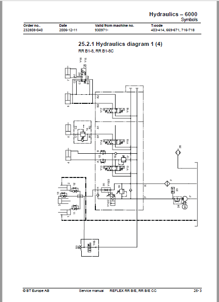
25 2 1 Hydraulics diagram 1 (4) 293
25 2 2 Hydraulics diagram 2 (4) 294
25 2 3 Hydraulics diagram 3 (4) 295
25 2 4 Hydraulics diagram 4 (4) 296
25 3 List of symbols 297
25 3 1 Component placement 1 (3) 299
25 3 2 Component placement 2 (3) 300
25 3 3 Component placement 3 (3) 301
25 4 Adjusting fork lowering 302
25 5 Adjusting the maximum lifting capacity 303
26- Hydraulic pump – 6140 305
26 1 General 305
26 2 Replacing the hydraulic pump 305
26 2 1 Dismantling 305
26 2 2 Assembling 306
27- Hydraulic connections – 6230 307
27 1 General 307
27 2 Tightening torque for hydraulic connections 307
27 2 1 Conical connection with O-ring 307
27 2 2 Tredo seal 308
27 2 3 Pipe coupling 308
27 2 4 Connection screwed into aluminium 308
27 2 5 Connection screwed into steel 309
Pressure class L 309
28- Mast mounted hose reel – 6370 311
28 1 General 311
28 2 Assembling 311
28 3 Check after assembly 312
29- Main lift cylinder – 6610 313
29 1 General 313
29 2 Tools 313
29 3 Dismantling the lift cylinders from the mast 314
29 4 Dismantling the cylinder 314
29 4 1 Dismantling the rod seal, guide ring, guide ring holder and locking ring in lift cylinder 315
29 4 2 Fit the locking ring, rod seal, guide ring and guide ring holder in the lift cylinder 315
29 4 3 Dismantling and assembling the hose rupture valve 316
29 5 Assembling the cylinder 316
29 5 1 Assembling the cylinder in the mast 316
30- Free lift cylinder – 6620 317
30 1 General 317
30 2 Tools 317
30 3 Dismantling 318
30 3 1 Dismantling the cylinder 319
30 4 Dismantle the rod seal and support ring 319
30 4 1 Assembling the rod seal and support ring 319
30 5 Dismantling the piston 320
30 5 1 Fitting the piston in the free lift cylinder 320
30 6 Dismantling and assembling the hose rupture valve 320
30 7 Assembling the cylinder 321
30 8 Assembly 321
31- Reach cylinder – 6650 323
31 1 General 323
31 2 Assembling and dismantling the reach cylinder 323
31 3 Dismantling 323
31 3 1 Dismantling the cylinder 324
31 3 2 Dismantle the rod seal and the support ring 324
31 3 3 Assembling the rod seal and the support ring 324
31 3 4 Dismantling the ram 325
31 3 5 Assembling the ram 325
31 3 6 Assembling the cylinder 325
31 4 Assembling 325
32- Tilt cylinder – 6660 1 327
32 1 General 327
32 2 Mast with valve on the fork carriage 327
32 2 1 Dismantling the fork carriage 327
32 2 2 Dismantling the cylinder 328
32 2 3 Dismantling the rod seal 328
32 2 4 Dismantling the ram 329
32 2 5 Assembling the ram 329
32 2 6 Assembling the rod seal 329
32 2 7 Assembling the cylinder 329
32 2 8 Assembling the fork carriage 330
32 3 Mast without valve on the fork carriage 331
32 3 1 Dismantling the fork carriage 331
32 3 2 Dismantling the cylinder 332
32 3 3 Dismantling the rod seal 332
32 3 4 Dismantling the ram 332
32 3 5 Assembling the ram 332
32 3 6 Assembling the rod seal 333
32 3 7 Assembling the cylinder 333
32 3 8 Assembling the fork carriage 333
33- Tilt cylinder – 6660 2 335
33 1 General 335
33 2 Dismantling the cylinder from the truck 335
33 3 Dismantling and assembling the cylinder 336
33 3 1 Dismantling the cylinder 336
33 3 2 Dismantle the seals and the support ring 336
33 3 3 Assembling the rod seal and the support ring 337
33 3 4 Dismantling the ram 337
33 3 5 Assembling the ram 337
33 3 6 Assembling the cylinder 337
33 4 Refitting the cylinder in the truck 338
34- Main mast -7100 339
34 1 General 339
34 2 List of tools 339
34 3 Transporting the truck 340
34 4 Assembling the mast 341
34 5 Dismantling the mast 346
34 6 Adjusting the play 347
34 6 1 Adjusting the mast play 350
Lateral play 350
34 6 2 Radial play 351
34 7 Assembly 351
34 8 Problem with the mast rollers 352
34 9 Adjusting the distance between the forks and floor 353
35- Main lift chain system – 7120 355
35 1 General 355
35 2 Checking the chain setting 355
35 3 Chain inspection 355
35 3 1 Noise 355
35 3 2 Surface rust 355
35 3 3 Rusty links 355
35 3 4 Stiff links 356
35 3 5 Bolt rotation 356
35 3 6 Loose bolts 356
35 3 7 Outline wear 357
35 3 8 Stretching 358
35 3 9 Damage 359
35 3 10 Damaged discs 359
35 3 11 Damaged bolts 359
35 3 12 Dirty chain 359
35 4 Cleaning 359
35 5 Lubrication 360
36- Lifting devices – 7400 361
36 1 General 361
36 1 1 Inspection intervals 361
36 1 2 Inspection 361
36 1 3 Surface cracks 361
36 1 4 Difference in height between the fork tips 361
36 1 5 Position locks 361
36 1 6 Legible markings 361
36 1 7 Fork blade and shaft 362
36 1 8 Assembly aid on fork 362
36 1 9 Repairs and testing 362
Repairs 362
Testing the yield point 362
Fork 363
Fixed extended fork 363
36 2 Extended forks with adjustable fork length 364
36 3 Manual telescopic forks 366
36 3 1 Assembly 366
36 3 2 Maintenance 367
36 4 Hydraulic telescopic forks 368
36 4 1 Assembly instructions 368
Telescopic forks with separate flow dividers 369
Commissioning of telescopic forks with separate flow dividers 370
Telescopic forks with integrated flow dividers 371
Commissioning of telescopic forks with integrated flow dividers 373
36 5 Maintenance 373
36 5 1 Maintenance 373
36 6 Troubleshooting, telescopic forks with separate flow dividers 374
36 6 1 Troubleshooting for telescopic forks with integrated flow dividers 376
36 6 2 Instructions for replacing hydraulic parts 378
Disassembly 378
Assembly 378
36 7 Fork carriage 380
36 7 1 Checking the fork carriage’s wearing strip 380
36 7 2 Lubrication 381
36 8 Fork spread unit 382
36 8 1 Servicing of fork spread unit 382
Replacing bearings 384
37- Battery charger – 8340 385
37 1 General 385
37 2 Installation 386
37 3 Functional description 386
37 3 1 Display functions 386
37 3 2 Charging process 386
37 3 3 Shutdown conditions 387
37 3 4 Delayed power on and charging 387
37 3 5 Extra charging 387
37 3 6 Equalised charging 388
37 3 7 Current and voltage characteristics 388
37 3 8 Safety shutdowns 388
37 3 9 Display and keyboard 389
Reading of analogue measurement values 389
Error indication and error messages 390
Reading statistics from the previous charge 391
Reading of long term statistics 392
Storing parameters 392
Reading parameters 393
Battery specific parameters 393
Charger specific parameters 394
Mains voltage codes 394
Other functions 394
Changing parameters 395
37 3 10 Acid circulation 395
General 395
BTM with acid circulation 395
Pump type APE, VPM 396
Pump type API 396
37 4 Service and maintenance 396
37 4 1 Basic programming, code 30 396
37 4 2 Resetting the statistics, code 31 396
37 4 3 Calibrating the measurement value 397
Calibrating the current’s zero value and temperatures, code 21 397
Calibrating the battery voltage’s measurement value, code 20 397
Calibrating the charging current, code 25 398
Calibrating the mains voltage display, code 26 398
37 4 4 Calibrating and programming API 398
Calibrating zero pressure 398
Calibrating the pressure 398
Programming the alarm limits 398
Programming the API function 399
37 4 5 Adjusting the charging characteristics 399
37 4 6 Trouble shooting 400
Error message, analysis and action 400
Errors without indication 401
37 4 7 Trouble shooting acid circulation 401
37 4 8 Service measures 401
Switching to the timer charger 402
Replacing the display card 402
Replacing the computer board 403
Replacing the mother board 403
Replacing the diodes 403
37 4 9 Preventive maintenance 403
38- Extra Lighting – 9360 405
39- Extra warning light/alarm – 9370 407
39 1 General 407
39 2 Wiring diagram 409
40- Positioning equipment – 9390 411
40 1 General 411
40 2 Height indication 412
40 3 Function 413
40 4 Display 414
40 5 Height pre-set 415
40 6 Function 416
40 7 Display 417
40 7 1 Description of the display symbols 418
40 8 Assembly of height pre-set 419
40 9 Programming 419
40 9 1 Programming a level 419
Collect level 419
Leave level 420
40 9 2 Deleting programmed levels 420
40 10 Automatic driving 421
40 10 1 Collect load 421
40 10 2 Depositing a load 422
40 10 3 Inspection 422
40 11 Parameters 423
40 11 1 Parameter 1 423
40 11 2 Parameter 2 423
40 11 3 Parameter 3 424
40 11 4 Parameter 4 424
40 11 5 Parameter 5 424
40 11 6 Parameter 7 425
40 11 7 Parameter 8 425
40 11 8 Parameter 9 425
40 12 Programming parameters 426
40 13 Error codes 428
41- TV equipment – 9390 429
41 1 General 429
41 2 Camera mounted on fork 429
41 2 1 Colour camera A51 430
41 2 2 Colour monitor A50 430
41 2 3 Voltage converter A10 432
42- Truck log system, code lock – 9420 433
42 1 General 433
42 2 SD 16 433
42 2 1 Login with code (5-digit) 433
42 2 2 Logout 433
42 3 Components 434
If the truck does not start: 436
42 4 I/O Module 436
43- Extra equipment – 9500 437
43 1 Dry powder extinguisher 437
In the event of fire, the powder extinguisher should be employed as follows: 437
43 1 1 Regular checks of the powder extinguisher – truck driver 438
43 1 2 Inspection of powder extinguisher in service inspection of the truck 438
44- Instructions for destruction 439
44 1 General 439
44 2 Procedure 439
44 3 Abbreviations 440
44 4 Sorting 440
44 5 Frame/chassis (0300) 441
44 5 1 Dismantling 441
Material handling 441
44 6 Operator’s seat, cushion (0620) 442
44 6 1 Dismantling 442
Material handling 442
44 7 Cab heating/ventilation (0630) 443
44 7 1 Dismantling 443
Material handling 443
44 8 Driver controls (0640) 444
44 8 1 Dismantling 444
Material handling 444
44 9 Interior fittings RR-B (0680) 445
44 9 1 Dismantling 445
Material handling 446
44 10 Interior fittings RR-E (0680) 447
44 10 1 Dismantling 447
Material handling 448
44 11 Interior fittings RR-B-CC (0680) 449
44 11 1 Dismantling 449
Material handling 450
44 12 Interior fittings RR-E-CC (0680) 451
44 12 1 Dismantling 451
Material handling 452
44 13 Rollover guard/head guard (0810) 453
44 13 1 Dismantling 453
Material handling 453
44 14 Finger protectors (0820) 453
44 14 1 Dismantling 453
Material handling 453
44 15 Finger/foot protectors (0820) 454
44 15 1 Dismantling 454
Material handling 454
44 16 Finger/foot protectors (0820) 455
44 16 1 Dismantling 455
Material handling 455
44 17 Electric motors (1700) 456
44 17 1 Dismantling 456
Material handling 456
44 18 Electric fan motor (1740) 457
44 18 1 Dismantling 457
Material handling 457
44 19 Drive unit, final gear (2500) 458
44 19 1 Dismantling 458
Material handling 458
44 20 Wheels (3500) 459
44 20 1 Dismantling 459
Material handling 459
44 21 Electric steering system (4300) 460
44 21 1 Dismantling 461
Material handling 461
44 22 General electric equipment (5100) 462
44 22 1 Dismantling 462
Material handling 462
44 23 Manöversystem, körfunktion (5300) 463
44 23 1 Dismantling 463
Material handling 463
44 24 Power system, drive function (5400) 464
44 24 1 Dismantling 464
Material handling 464
44 25 Control system, operation function (5500) 465
44 25 1 Dismantling 465
Material handling 465
44 26 Steering/protective electronics (5700) 466
44 26 1 Dismantling 466
Material handling 466
44 27 Hydraulic unit (6100) 467
44 27 1 Dismantling 468
Material handling 468
44 28 Hydraulic system, fitted on the chassis (6200) 469
44 28 1 Dismantling 470
Material handling 470
44 29 Hydraulic system, fitted on the mast (6300) 471
44 29 1 Dismantling 471
Material handling 471
44 30 Hydraulcylindrar (6600) 472
44 30 1 Dismantling 473
Material handling 473
44 31 Main mast (7100) 474
44 31 1 Dismantling 474
Material handling 474
44 32 Lift fork (7410) 475
44 32 1 Dismantling 475
Material handling 475
44 33 Optional electric equipment (9300) 475
44 33 1 Dismantling 475
Material handling 475
44 34 Radio/CD player (9330) 476
44 34 1 Dismantling 476
Material handling 476
44 35 Extra work light (9360) 477
44 35 1 Dismantling 477
Material handling 477
44 36 Optional electric equipment (9400) 478
44 36 1 Dismantling 478
Material handling 478
44 37 Optional electric equipment (9400) 479
44 37 1 Dismantling 479
Material handling 479
IMAGES PREVIEW OF THE MANUAL:

VIDEO PREVIEW OF THE MANUAL:

PLEASE NOTE:
- This is the SAME manual used by the dealers to troubleshoot any faults in your vehicle. This can be yours in 2 minutes after the payment is made.
- Contact us at [email protected] should you have any queries before your purchase or that you need any other service / repair / parts operators manual.
S.V


