

Bobcat 325 328 Service Manual 6901138 – PDF DOWNLOAD
FILE DETAILS:
Bobcat 325 328 Service Manual 6901138 – PDF DOWNLOAD
Language : English
Pages : 800
Downloadable : Yes
File Type : PDF
Size: 28.4 MB
DESCRIPTION:
Bobcat 325 328 Service Manual 6901138 – PDF DOWNLOAD
FOREWORD
This manual is for the Bobcat excavator mechanic. It provides necessary servicing and adjustment procedures for the Bobcat excavator and its component parts and systems. Refer to the Operation & Maintenance Manual for operating instructions, starting procedure, daily checks, etc
A general inspection of the following items must be made after the excavator has had service or repair:
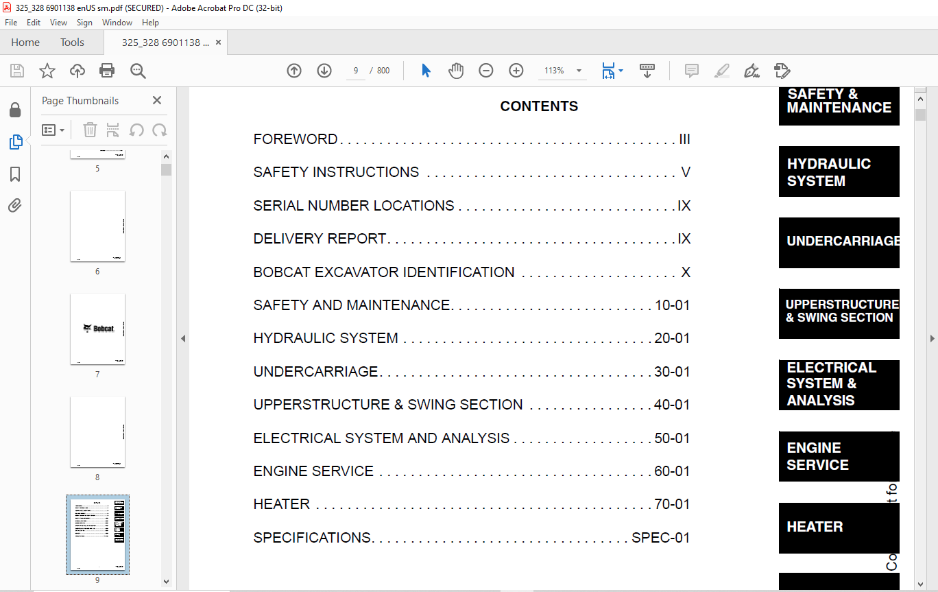
TABLE OF CONTENTS:
Bobcat 325 328 Service Manual 6901138 – PDF DOWNLOAD
MAINTENANCE SAFETY 3
ALPHABETICAL INDEX 5
CONTENTS 9
FOREWORD 11
SAFETY INSTRUCTIONS 13
Fire Prevention 15
SERIAL NUMBER LOCATIONS 17
Bobcat Excavator Serial Number 17
Engine Serial Number 17
DELIVERY REPORT 17
BOBCAT EXCAVATOR IDENTIFICATION 18
SAFETY AND MAINTENANCE 19
LIFTING AND BLOCKING THE EXCAVATOR 21
Procedure 21
SWING LOCK 23
Operation 23
LIFTING THE EXCAVATOR 25
Procedure 25
OPERATOR CAB (ROPS / TOPS) (IF EQUIPPED) 27
Emergency Exit 27
Cab Door 27
Front Window 27
TRANSPORTING THE EXCAVATOR 29
Procedure 29
TAILGATE 31
Opening And Closing The Tailgate (Early Models) 31
Adjusting The Bumper (Early Models) 31
Adjusting The Tailgate Latch (Early Models) 32
Opening And Closing The Tailgate (Later Models) 32
Adjusting The Tailgate Latch (Later Models) 33
Adjusting The Bumper (Later Models) 33
SERVICE SCHEDULE 35
Chart 35
AIR CLEANER SERVICE 37
Daily Check 37
Replacing The Filters 37
HEATER AIR FILTERS (WITH CAB OPTION ONLY) 39
Recirculation Filter 39
Fresh Air Filter 39
ENGINE COOLING SYSTEM 41
Cleaning The Cooling System 41
Checking The Coolant Level 41
Replacing The Coolant 42
FUEL SYSTEM 45
Fuel Specification 45
Filling The Fuel Tank 45
Removing Water From The Fuel Filter 45
Fuel Filter 45
Removing Air From The Fuel System 46
Draining The Fuel Tank 46
ENGINE LUBRICATION SYSTEM 47
Checking Engine Oil 47
Replacing Oil And Filter 47
HYDRAULIC SYSTEM 49
Checking And Adding Fluid 49
Replacing the Hydraulic Filter 49
Replacing the Case Drain Filter 50
Replacing the Hydraulic Fluid 50
Diagnostic Couplers 51
LUBRICATING THE EXCAVATOR 53
Procedure 53
TRAVEL MOTOR 55
Checking Oil Level 55
Draining The Travel Motor 55
SPARK ARRESTOR MUFFLER (IF EQUIPPED) 57
Cleaning The Spark Arrestor Muffler 57
HYDRAULIC SYSTEM 59
HYDRAULIC/HYDROSTATIC SCHEMATICS 65
HYDRAULIC SYSTEM INFORMATION 70
Glossary Of Hydraulic / Hydrostatic Symbols 70
Troubleshooting Chart 74
BOOM CYLINDER 78
Checking The Boom Cylinder 78
Removal And Installation 80
Parts Identification 82
Disassembly 83
Assembly 85
ARM CYLINDER 88
Checking The Arm Cylinder 88
Removal And Installation 90
Parts Identification 91
Disassembly 92
Assembly 94
BOOM OFFSET CYLINDER 98
Checking The Boom Offset Cylinder 98
Removal And Installation 100
Parts Identification 102
Disassembly 103
Assembly 105
BUCKET CYLINDER 108
Checking The Bucket Cylinder 108
Removal And Installation 110
Parts Identification 111
Disassembly 112
Assembly 114
BLADE CYLINDER 118
Checking The Blade Cylinder 118
Removal And Installation 120
Parts Identification 121
Disassembly 122
Assembly 124
MAIN RELIEF VALVES 128
Testing And Adjusting The Main Relief Valves (S/N 232312386 & Below, 232412117 & Below, 232412128 And 232412129) 128
Testing And Adjusting The Main Relief Valves (S/N 232312387 & Above, 232412118-232412127 And 232412130 & Above) 132
PORT RELIEF VALVES 136
Testing And Adjusting Port Relief Valve Pressure (S/ N 232312386 & Below And 232412117 & Below, 232412128 And 232412129) 136
Testing Port Relief Valve Pressure (S/N 232312387 & Above And 232412118-232412127 And 232412130 & Above) 137
CROSSPORT RELIEF VALVES 140
Testing And Adjusting The Crossport Relief Valves 140
SYSTEM PRESSURES AT GAUGE PORT SPECIFICATIONS 140
PRESSURE REDUCING VALVE (S/N 232312386 & BELOW AND 232412117 & BELOW, 232412128 AND 232412129) 142
Testing And Adjusting The Pressure Reducing Valve 142
PRESSURE REDUCING VALVE (S/N 232312387 & ABOVE AND 232412118-232412127 AND 232412130 & ABOVE) 144
Testing And Adjusting The Pressure Reducing Valve 144
HYDRAULIC CONTROL VALVE (S/N 232312386 & BELOW, 232412117 & BELOW, 232412128 AND 232412129) 148
Description 148
Removal And Installation 148
Control Valve Identification 152
Disassembly 153
Right Travel Valve Section Disassembly And Assembly 154
Boom Offset Valve Section Disassembly And Assembly 157
Boom Valve Section Disassembly And Assembly 160
Left Travel Valve Section Disassembly And Assembly 163
Arm Valve Section Disassembly And Assembly 165
Bucket Valve Section Disassembly And Assembly 168
Auxiliary Valve Section Disassembly And Assembly 170
Boost Valve Section Disassembly And Assembly 173
Blade Valve Section Disassembly And Assembly 175
Swing Valve Section Disassembly And Assembly 177
Assembly 179
HYDRAULIC CONTROL VALVE (S/N 232312387 & ABOVE, 232412118-232412127 AND 232412130 & ABOVE) 186
Description 186
Removal And Installation 186
Control Valve Identification 192
Disassembly 193
Right Travel Valve Section Disassembly And Assembly 194
Boom Offset Valve Section Disassembly And Assembly 200
Boom Valve Section Disassembly And Assembly 206
Left Travel Valve Section Disassembly And Assembly 210
Arm Valve Section Disassembly And Assembly 215
Bucket Valve Section Disassembly And Assembly 219
Auxiliary Valve Section Disassembly And Assembly 223
Boost Valve Section Disassembly And Assembly 227
Blade Valve Section Disassembly And Assembly 231
Swing Valve Section Disassembly And Assembly 236
Assembly 240
HYDRAULIC PUMP 248
Description 248
Torque Adjustment 248
Testing The Piston Pump 249
Testing The Gear Pump 251
Testing The Auxiliary Hydraulic Flow 253
Removal And Installation 254
Coupler Removal And Installation 255
Gear Pump Parts Identification 256
Piston Pump Parts Identification 257
Disassembly 258
Gear Pump Disassembly 259
Gear Pump Assembly 262
Piston Pump Disassembly 264
Piston Pump Assembly 272
Assembly 281
MANIFOLD ASSEMBLY/ACCUMULATOR (S/N 232311950 & BELOW AND 232411763 & BELOW) 282
Manifold Description 282
Removal And Installation 282
MANIFOLD ASSEMBLY (S/N 232311950 & BELOW AND 232411763 & BELOW) 286
Parts Identification 286
Disassembly 287
Assembly 295
MANIFOLD ASSEMBLY/ACCUMULATOR (S/N 232311951 & ABOVE AND 232411764 & ABOVE) 304
Manifold Description 304
Removal And Installation 304
MANIFOLD ASSEMBLY (S/N 232311951 & ABOVE AND 232411764 & ABOVE) 308
Parts Identification 308
Disassembly 309
Assembly 319
TRAVEL MOTOR 332
Removal And Installation 332
Parts Identification 334
Disassembly 335
Assembly 342
SWIVEL JOINT 352
Removal And Installation (With The Upperstructure Removed) 352
Removal And Installation (Through Bottom Access Cover) 352
Parts Identification 354
Description 355
Disassembly 355
Assembly 356
SWING MOTOR 360
Removal And Installation 360
Parts Identification 363
Disassembly 364
Assembly 366
Cross Port Relief Valve Parts Identification 371
Cross Port Relief Valve Disassembly 372
Cross Port Relief Valve Assembly 374
SWING MOTOR DRIVE CARRIER 376
Removal And Installation 376
Parts Identification 377
Disassembly 378
Assembly 380
CONTROL PATTERN SELECTOR VALVE 384
Removal And Installation 384
Parts Identification 384
Disassembly 385
Assembly 386
RIGHT CONTROL LEVER (JOYSTICK) (S/N 232312386 & BELOW, 232412117 & BELOW, 232412128 AND 232412129) 388
Testing 388
Handle Removal And Installation 389
Joystick Assembly, Removal And Installation 393
Parts Identification 395
Disassembly 396
LEFT CONTROL LEVER (JOYSTICK) (S/N 232312386 & BELOW, 232412117 & BELOW, 232412128 AND 232412129) 400
Testing 400
Handle Removal And Installation 401
Joystick Assembly Removal And Installation 404
Parts Identification 407
Disassembly 408
LEFT CONTROL LEVER (JOYSTICK) (S/N 232312387 & ABOVE, 232412118-232412127 AND 232412130 & ABOVE) 412
Testing 412
Handle Removal And Installation 413
Joystick Assembly Removal And Installation 416
Parts Identification 418
Disassembly 419
Assembly 423
RIGHT CONTROL LEVER (JOYSTICK) (S/N 232312387 & ABOVE, 232412118-232412127 AND 232412130 & ABOVE) 430
Testing 430
Handle Removal And Installation 431
Joystick Assembly Removal And Installation 435
Parts Identification 437
Disassembly 438
Assembly 442
HYDRAULIC FILTER 448
Removal And Installation 448
HYDRAULIC RESERVOIR 450
Removal And Installation 450
OIL COOLER 452
Removal And Installation 452
DIRECT TO TANK VALVE 454
Removal And Installation 454
Disassembly And Assembly 455
BUILD UP VALVE 456
Description 456
Removal And Installation 456
Disassembly And Assembly 456
CASE DRAIN FILTER 458
Removal And Installation 458
UNDERCARRIAGE 460
BLADE 462
Removal And Installation 462
TRACKS 464
Track Lug Height 464
Adjustment 464
Rubber Track Removal And Installation 467
Steel Track Removal And Installation 469
TRACK FRAME 472
Disassembly And Assembly 472
Recoil Spring Disassembly And Assembly 474
TRACK DAMAGE IDENTIFICATIONS 478
Cutting Of Steel Cords 478
Abrasion Of Embedded Metals 479
Separation Of Embedded Metals 480
Separation Of Embedded Metals Due To Corrosion 481
Cuts On The Lug Side Rubber 482
Cracks On The Lug Side Rubber Due To Fatigue 483
Lug Abrasion 484
Cracks And Cuts On The Lug Side Rubber 485
Abrasion Of The Track Roller Side 486
Cuts On The Edges Of Track Roller Side 487
TRACK IDLER 490
Parts Identification (S/N 232311036 & Below And 232411019 & Below) 490
Disassembly (S/N 232311036 & Below And 232411019 & Below) 491
Assembly (S/N 232311036 & Below And 232411019 & Below) 493
Parts Identification (S/N 232311037 & Above And 232411020 & Above) 497
Disassembly (S/N 232311037 & Above And 232411020 & Above) 498
Assembly (S/N 232311037 & Above And 232411020 & Above) 500
TRACK ROLLER 504
Parts Identification (S/N 232311036 & Below And 232411019 & Below) 504
Disassembly (S/N 232311036 & Below And 232411019 & Below) 505
Assembly (S/N 232311036 & Below And 232411019 & Below) 507
Parts Identification (S/N 232311037 & Above And 232411020 & Above) 511
Disassembly (S/N 232311037 & Above And 232411020 & Above) 512
Assembly (S/N 232311037 & Above And 232411020 & Above) 513
SWING CIRCLE GEAR 516
Removal And Installation 516
Swing Bearing Removal 518
Swing Bearing Installation 519
Alignment Pins (Not Threaded) 521
UPPERSTRUCTURE & SWING SECTION 522
UPPERSTRUCTURE 526
Removal And Installation 526
Swing Bearing Removal 528
Swing Bearing Installation 529
Alignment Pins (Not Threaded) 531
ROPS CANOPY 534
Removal And Installation 534
CAB 538
Removal And Installation 538
Door Removal And Installation 541
Front Window Removal And Installation 542
Lower Front Window Removal And Installation 544
Right Side Rear Sliding Window Removal And Installation 545
Right Side Front Sliding Window Removal And Installation 546
Right Side Panel And Window Assembly Removal And Installation 547
Door, Left Side, Rear And Upper Front Window Removal And Installation 550
STANDARD SEAT AND SEAT MOUNT 552
Removal And Installation 552
SUSPENSION SEAT AND SEAT MOUNT 554
Removal And Installation 554
RIGHT CONSOLE 556
Console Cover Removal And Installation 556
Console Base Removal And Installation 557
LEFT CONSOLE 562
Lower Console Cover Removal And Installation 562
Upper Console Cover Removal And Installation 564
Compression Spring Removal And Installation 565
Lock Lever Removal And Installation 566
Upper Console Removal And Installation 567
Console Switch Removal And Installation 569
Disassembly And Assembly 570
Console Base Removal And Installation 572
ENGINE SPEED CONTROL 574
Removal And Installation 574
BLADE CONTROL 576
Lever Removal And Installation 576
Linkage Removal And Installation 577
Linkage Bar Removal And Installation 579
Lower Linkage Removal And Installation 580
RIGHT PEDAL AND LINKAGE 584
Pedal Removal And Installation 584
Right Pedal Disassembly And Assembly 585
Linkage Removal And Installation 587
Adjustment 590
TRAVEL CONTROLS 592
Removal And Installation 592
Disassembly And Assembly 593
Adjustment 596
FLOOR MAT AND FLOOR PANELS 598
Removal And Installation 598
FUEL TANK 600
Removal And Installation 600
HORN 606
Removal And Installation 606
SWING FRAME 608
Boom Swing Bracket Removal And Installation 608
Boom Swing Bracket Hose Installation 612
Bushing Removal 613
Bushing Installation 614
BOOM 616
Removal And Installation 616
Boom Bushing Removal And Installation 617
ARM 618
Removal And Installation 618
Arm To Boom Bushing Removal And Installation 618
Arm To Bucket And Bucket Link Bushing Removal And Installation 619
BUCKET 620
Bucket Teeth Removal And Installation 620
Bucket Side Cutting Edge Removal And Installation 621
TAILGATE 622
Removal And Installation 622
Release Rod Removal And Installation 623
Latch Removal And Installation 624
Release Rod Removal And Installation (Early Models) 624
Latch Removal And Installation (Early Models) 625
Latch Removal And Installation (Later Models) 626
X-CHANGE™ 628
Removal And Installation 628
Disassembly 630
Assembly 635
RIGHT SIDE COVER 642
Removal And Installation 642
ELECTRICAL SYSTEM & ANALYSIS 644
ELECTRICAL SCHEMATIC 646
ELECTRICAL SYSTEM INFORMATION 647
Glossary Of Electrical Symbols 647
Troubleshooting Chart 651
Description 652
Fuse Location 652
BATTERY 653
Servicing 653
Removal And Installation 654
Using A Booster Battery (Jump Starting) 655
ALTERNATOR 657
Adjusting The Alternator Belt 657
Description 657
Tests 658
Alternator Output Test 658
Full Field Test 659
Alternator Regulator Test 659
Removal And Installation 660
Disassembly And Assembly 662
STARTER 663
Removal And Installation 663
Parts Identification 664
Disassembly 665
Inspection And Repair 670
Assembly 673
LIGHTS 679
Removal And Installation 679
Disassembly And Assembly 680
FUEL LEVEL SENDER 681
Removal And Installation 681
Testing 681
DIAGNOSTICS SERVICE CODE 683
Number Codes List 683
ENGINE SERVICE 685
TROUBLESHOOTING 687
Chart 687
MUFFLER 689
Removal And Installation 689
AIR CLEANER 691
Removal And Installation 691
RADIATOR 693
Removal And Installation 693
ENGINE COMPONENTS AND TESTING 697
Valve Clearance Adjustment 697
Engine Compression Checking 697
Fuel Shutoff Solenoid Adjustment 699
Fuel Shutoff Solenoid Removal And Installation 699
Fuel Injection Pump Check 700
Fuel Injection Pump Removal And Installation 701
Fuel Injection Pump Timing 702
Fuel Injector Nozzles Removal And Installation 703
Checking The Injector Nozzle 705
Glow Plug Removal And Installation 706
Glow Plug Checking 707
ENGINE 709
Removal And Installation 709
ENGINE FLYWHEEL 715
Removal And Installation 715
Flywheel Ring Gear 717
RECONDITIONING THE ENGINE 719
Cylinder Head Removal And Installation 719
Cylinder Head Disassembly And Assembly 720
Cylinder Head Servicing 721
Cylinder Head Top Clearance 722
Valve Guide, Checking 722
Reconditioning The Valve And Valve Seat 724
Valve Spring 725
Rocker Arm And Shaft Checking 726
Timing Gearcase Cover Removal And Installation 726
Idler Gear And Camshaft Removal And Installation 729
Idler Gear And Shaft Servicing 731
Timing Gears Checking Backlash 732
Fuel Camshaft Removal And Installation 732
Fuel Camshaft Governor 733
Crankshaft Gear Removal And Installation 733
Oil Pump Removal And Installation 734
Oil Pump Service 734
Engine Oil Pressure, Checking 735
Relief Valve 736
Piston And Connecting Rod Removal And Installation 736
Piston And Connecting Rod Servicing 738
Connecting Rod Alignment 740
Crankshaft And Bearings Removal And Installation 741
Crankshaft And Bearings, Servicing 743
Cylinder Bore, Checking 745
Water Pump Removal And Installation 745
Water Pump Disassembly And Assembly 746
Fan Removal And Installation 746
HEATER 749
HEATER UNIT 751
Removal And Installation 751
Disassembly And Assembly 752
HEATER COIL 753
Removal And Installation 753
HEATER FAN 755
Removal And Installation 755
Disassembly And Assembly 756
Resistor Removal And Installation 757
Wire Connector Removal And Installation 758
HEATER VALVE 761
Removal And Installation 761
SPECIFICATIONS 763
HYDRAULIC EXCAVATOR SPECIFICATIONS (325) 765
Machine Dimensions 765
Lifting Capacity 766
Weights 766
Controls 766
Engine 767
Electrical 767
Hydraulic System 767
Swing System 768
Hydraulic Cylinders 768
Drive System 768
Brakes 768
Undercarriage 768
STD Track 769
Capacities 769
Digging Force 769
HYDRAULIC EXCAVATOR SPECIFICATIONS (325 W/LONG ARM KIT & 328) 770
Machine Dimensions 770
Lifting Capacities 771
Weights 771
Controls 771
Engine 772
Electrical 772
Hydraulic System 772
Swing System 773
Hydraulic Cylinders 773
Drive System 773
Brakes 773
Undercarriage 773
STD Track 774
Capacities 774
Digging Force 774
ENGINE SPECIFICATIONS 775
Fuel Injection Nozzles 775
Fuel Injection Pump 775
Cylinder Head 775
Valves 775
Valve Springs 776
Valve Timing 776
Rocker Arms 776
Camshaft 776
Tappet 776
Cylinders 777
Piston Rings 777
Pistons 777
Connecting Rods 777
Oil Pump 777
Crankshaft 778
Thermostat 778
Timing Gear 779
Engine Bolt Torque 779
Crankshaft Re-Grind Data 780
TORQUE SPECIFICATIONS 781
Torque For General SAE Bolts 781
Torque For General Metric Bolts 782
HYDRAULIC CONNECTION SPECIFICATIONS 783
O-Ring Face Seal Connection 783
Straight Thread O-Ring Fitting 783
Tubelines And Hoses 783
Flare Fitting 783
O-Ring Flare Fitting 784
Port Seal Fitting 786
HYDRAULIC FLUID SPECIFICATIONS 787
Specifications 787
FUEL, COOLANT AND LUBRICANTS 789
Chart 789
CONVERSIONS 791
Decimal And Millimeter Equivalents 791
U S To Metric Conversion 792
SMR 793
325/328-1 793
325/328-2 795
325/328-3 797
325/328-4 799
IMAGES PREVIEW OF THE MANUAL:

VIDEO PREVIEW OF THE MANUAL:
PLEASE NOTE:
- This is the SAME MANUAL used by the dealerships to diagnose your vehicle
- No waiting for couriers / posts as this is a PDF manual and you can download it within 2 minutes time once you make the payment.
- Your payment is all safe and the delivery of the manual is INSTANT – You will be taken to the DOWNLOAD PAGE.
- So have no hesitations whatsoever and write to us about any queries you may have : heydownloadss @gmail.com
S.M


