
Bobcat 1600 Loader Service Manual 6566906 (6-12) – PDF DOWNLOAD
FILE DETAILS:
Bobcat 1600 Loader Service Manual 6566906 (6-12) – PDF DOWNLOAD
Language : English
Pages : 282
Downloadable : Yes
File Type : PDF
IMAGES PREVIEW OF THE MANUAL:

DESCRIPTION:
Bobcat 1600 Loader Service Manual 6566906 (6-12) – PDF DOWNLOAD
FOREWORD:
This manual is for the Bobcat loader mechanic. It provides necessary servicing and adjustment procedures for the Bobcat loader and its component parts and systems. Refer to the Operation & Maintenance Manual for operating instructions, starting procedure, daily checks, etc.
SAFETY INSTRUCTIONS:
Safety Alert Symbol: This Safety Symbol is used for important safety messages. When you see this
symbol follow the safety message to avoid personal injury or death.
1. The Delivery Report is used to assure that complete instructions have been given to the new owner and that the
machine is in safe operating condition.
2. The Operation & Maintenance Manual delivered with the loader gives operating information as well as routine
maintenance and service procedures. It is a part of the loader and must stay with the machine when it is sold.
3. The loader has machine signs (decals) which instruct on the safe care and operation. The signs and their locations
are shown in the Operation & Maintenance Manual. Replacement signs are available from Bobcat loader dealers.
4. The FIEI Manual delivered with the loader gives general safety information.
5. The Service Manual and Parts Manual are available from Bobcat loader dealers for use by mechanics to do shop–type
service and repair work.
Wear tight fitting clothing and any other required safety apparel when operating or servicing the loader.
Wear safety glasses when maintaining or servicing the loader.
Exhaust gases can kill, vent engine exhaust outdoors.
Know where fire extinguishers and first aid kits are located and how to use them.
Do not run the Bobcat loader where exhaust, arcs, sparks or hot components can contact flammable material, explosive
dust or gases.
Check fuel and hydraulic tubes, hoses and fittings for damage and leakage. Never use open flame or bare skin to check
for leaks. Tighten or replace any parts that show leakage. Always clean fluid spills. Do not use gasoline or diesel fuel for
cleaning parts. Use commercial nonflammable solvents.
Clean the loader before doing any welding. Cover rubber hoses, battery and all other flammable parts. Keep a fire
extinguisher near the loader when welding.
Have good ventilation when welding or grinding painted parts. Wear a dust mask when grinding painted parts. Toxic dust
and gas can be produced.
Stop the engine and let it cool before adding fuel. No smoking!
Use the preocedure in this manual for connecting battery.
Use the procedure in this manual for cleaning the spark arrestor muffler after each 100 hours of operation.
TABLE OF CONTENTS:
Bobcat 1600 Loader Service Manual 6566906 (6-12) – PDF DOWNLOAD
MAINTENANCE SAFETY 3
CONTENTS 5
FOREWORD 7
SAFETY INSTRUCTIONS 9
SERIAL NUMBER LOCATIONS 10
LOADER SERIAL NUMBER 10
ENGINE SERIAL NUMBER 10
DELIVERY REPORT 10
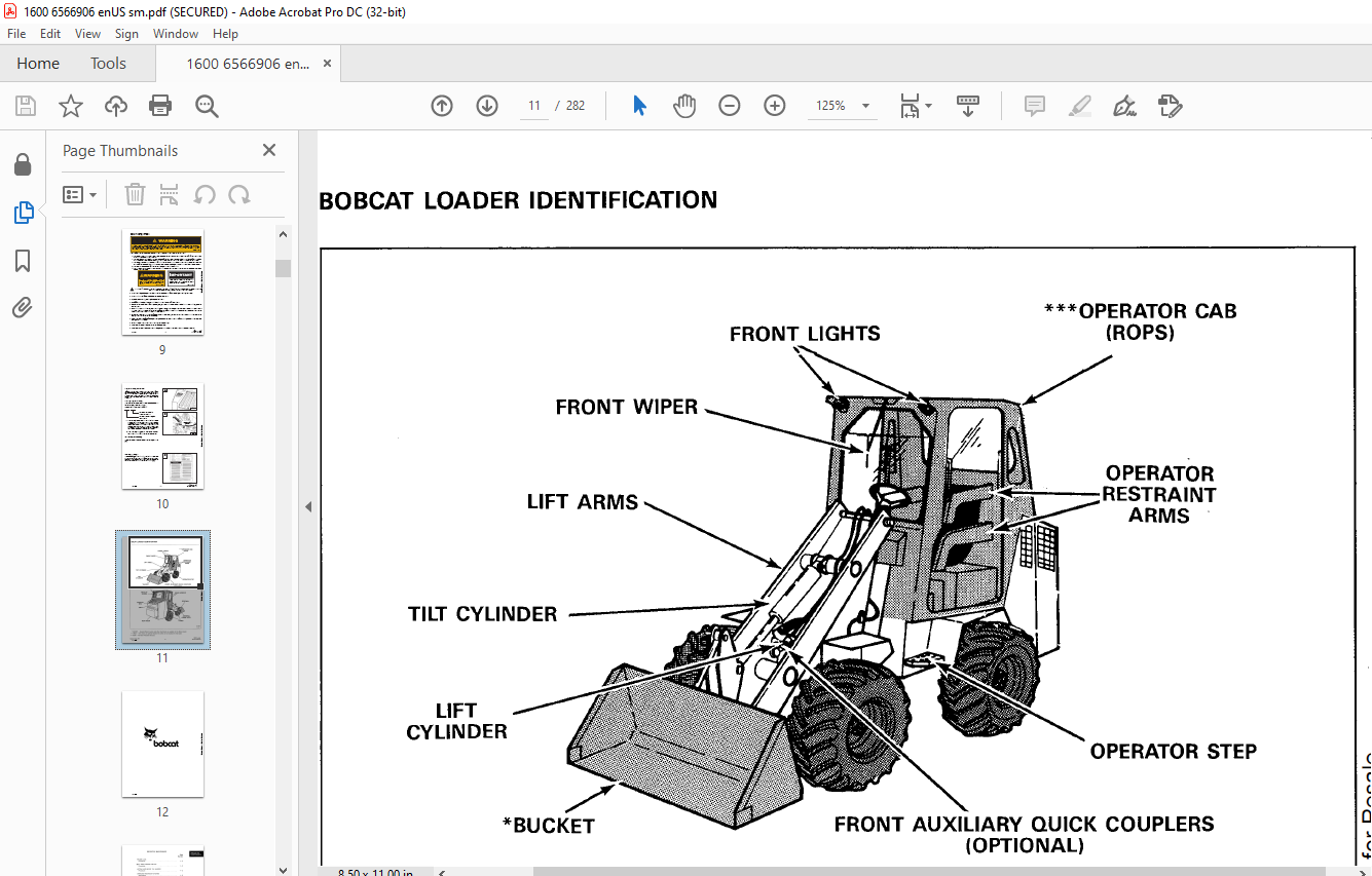
BOBCAT LOADER IDENTIFICATION 11
PREVENTIVE MAINTENANCE 13
SERVICE SCHEDULE 15
LIFTING AND BLOCKING THE LOADER 16
Procedure 16
LIFT ARM SUPPORT DEVICE 17
Procedure 17
FRAME LOCK 17
Procedure 17
TRANSPORTING THE BOBCAT LOADER 18
Procedure 18
OPERATOR RESTRAINT SYSTEM 19
Description 19
Inspection Of The Operator Restraint System 19
Serviceing The Operator Restraint System 19
USING AND EXTRA BATTERY (JUMP STARTING) 20
Procedure 20
HYDRAULIC SYSTEM 21
HYDRAULIC/HYDROSTATIC SCHEMATICS 23
HYDRAULIC SYSTEM (S/N 12001 & ABOVE) 47
TROUBLESHOOTING 49
HYDRAULIC SYSTEM INFORMATION 50
Flare Connections 50
O-Ring Face Seal Connection 50
Straight Thread O-Ring Fitting 50
Tubelines And Hoses 50
LIFT CYLINDER 51
Checking The Lift Cylinder 51
Removal And Installation 51
TILT CYLINDER 52
Checking The Tilt Cylinder 52
Removal And Installation 52
STEERING CYLINDER 53
Checking The Steering Cylinder 53
Removal And Installation 53
HYDRAULIC CONTROL VALVE 54
Check The Main Relief Valve 54
Main Relief Valve Removal And Installation 54
Removal And Installation 55
HYDRAULIC PUMP 56
Checking Output Of The Hydraulic Pump 56
Removal And Installation 57
BUCKET POSITION VALVE (S/N 12026 & BELOW) 58
Removal And Installation 58
Disassembly And Assembly 58
BUCKET POSITION VALVE (S/N 12027 & ABOVE) 60
Removal And Installation 60
STEERING CONTROL VALVE 62
Checking Steering Relief Valve 62
Removal And Installation 63
Disassembly 64
Inspection 66
Assembly 67
PORT BLOCK 71
Removal And Installation 71
Disassembly And Assembly 71
PRIORITY VALVE 72
Removal And Installation 72
Disassembly And Assembly 72
Adjustment Of Steering Relief Valve 72
HYDRAULIC / HYDROSTATIC FLUID RESERVOIR 73
Removal And Installation 73
HYDRAULIC SYSTEM (S/N 11999 & BELOW) 75
HYDRAULIC CONTROL VALVE 77
Checking The Main Relief Valve 77
Mian relief Valve Removal And Installation 78
Checking Output Of The Hydraulic Pump 79
Removal And Installation 80
STEERING CONTROL VALVE 81
Checking Steering Relief Valve 81
PORT BLOCK 82
Removal And Installation 82
Cold Weather By-Pass Valve 82
Servo Relief Valve 82
Charge Relief Valve 82
OIL COOLER 83
Removal And Installation 83
Oil Cooler Service 83
HYDROSTATIC SYSTEM 85
HYDROSTATIC SYSTEM (S/N 12001 & ABOVE) 87
TROUBLESHOOTING 89
HYDROSTATIC SYSTEM INFORMATION 90
High Pressure Relief Replenishing Valves Function 90
CENTERING MECHANISM 91
Foot Pedal Angle Adjustment 91
Removal And Installation 91
Centering Mechanism Spring Replacement 91
Adjusting The Springs In The Centering Mechanism 93
Micro Switch Adjustment 94
HYDROSTATIC MOTOR 95
Removal And Installation 95
TWO SPEED VALVE 96
Removal And Installation 96
Disassembly And Assembly 97
HYDROSTATIC PUMP 98
Checking Charge Pressure 98
Checking The High Pressure Relief Replenishing Valve 98
Neutral Adjustment 99
Removal And Installation 100
HYDROSTATIC SYSTEM (S/N 11999 & BELOW) 103
TROUBLESHOOTING 105
SERVO CONTROL 106
Neutral Adjustment 106
Removal And Installation 107
Disassembly And Assembly 108
Servo Control Pressure 109
CENTERING MECHANISM 110
Removal And Installation 110
Centering Mechanism Spring Replacement 111
Adjusting The Springs in The Centering Mechanism 112
Neutral Safety Switch Adjustment 113
HYDROSTATIC MOTOR 114
Removal And Installation 114
Manifold Block 114
HYDROSTATIC PUMP 116
Checking Charge Pressure 116
Replenishing Valves 116
Removal And Installation 117
DRIVE SYSTEM 119
TROUBLESHOOTING 121
DRIVE SHAFT 122
Removal And Installation 122
AXLE AND DIFFERENTIAL 123
Rear Axle Removal And Installation 123
Front Axle Removal And Installation 124
Wheel RPM 125
Hub Removal 126
Hub Installation 129
Differential Disassembly 131
Ring Gear Removal 132
Ring Gear Installation 134
Pinion Shaft And Drop Gear Removal 134
Assembly Procedure Explanation 136
Checking Differential Assembly End Play (Without Pinion Shaft Installed) 137
Pinion Shaft Installation 138
Differential Assembly Installation 142
BRAKE (S/N 12001 & ABOVE) 147
Removal And Installation 147
Disassembly And Assembly 147
BRAKE VALVE 153
Removal And Installation 153
Disassembly And Assembly 153
BRAKE (S/N 11242 – 11999) 154
Removal And Installation 154
Disassembly And Assembly 154
Moving The Loader 156
BRAKE (S/N 11241 & bELOW) 157
Removal And Installation 157
Disassembly And Assembly 157
Removing Air From The Brake System 158
MAIN FRAME 159
OPERATOR CAB 161
Removal And Installation 161
REAR DOOR 162
Door Latch Adjustment 162
Removal And Installation 162
LIFT ARMS 163
Removal And Installation 163
BOB-TACH 164
Removal And Installation 164
FLOOR PANEL 165
Removal And Installation 165
SEAT AND SEAT PAN 166
Removal And Installation 166
STEERING COLUMN COVER 167
Removal And Installation 167
TUBELINE COVER 168
Removal And Installation 168
FUEL TANK 168
Removal And Installation 168
LOADER FRAME DISASSEMBLY AND ASSEMBLY 169
Description 169
Seperating The Front Section From The Center Section 169
Connecting The Front Section To The Center Section 171
Seperating The Rear Section From The Center Section (S/N 11999 & Below Only) 171
Rear Section Service Procedures (S/N 11999 & Below Only) 175
Connecting The Rear Section To The Center Section (S/N 11999 & Below Only) 176
ELECTRICAL SYSTEM 177
ELECTRICAL SCHEMATICS 180
ELECTRICAL SYSTEM INFORMATION 197
Description 197
TROUBLESHOOTING 197
BATTERY 198
Checking The Battery 198
Removal And Installation 198
DIODES 198
Checking The Diodes 198
ALTERNATOR (DELCO) 199
Alternator Belt Adjustment 199
Checking Alternator Wiring Harness 199
Checking Alternator Output 200
Checking Alternator Regulator 200
Removal And Installation 200
Disassembly And Assembly 201
MELROE ALTERNATOR 204
Checking The Alternator Output 204
Checking The Alternator Regulator 204
Removal And Installation 205
Disassembly And Assembly 206
STARTER 209
Checking The Starter 209
Removal And Installation 209
Disassembly And Assembly 210
Inspection 211
Replacing The Brushes 211
ENGINE SERVICE 213
TROUBLESHOOTING 215
VALVE CLEARANCE 216
Adjustment 216
ENGINE COMPRESSION 217
Checking 217
FUEL FILTER 218
Water Trap 218
Fuel Filter Element 218
REMOVING AIR FROM THE FUEL SYSTEM 219
Procedure 219
ENGINE SHUT-OFF SOLENOID 219
Removal And Installation 219
THROTTLE TENSION ADJUSTMENT 219
Procedure 219
FUEL INJECTION PUMP 220
Removal And Installation 220
Checking The Injection Pump 221
Timing The Injection Pump 221
FUEL INJECTOR NOZZLES 222
Removal And Installation 222
Checking The Injector Nozzles 223
GLOW PLUGS 224
Removal And Installation 224
Checking The Glow Plug 224
ENGINE 225
Removal And Installation 225
RADIATOR AND OIL COOLER 228
Removal And Installation 228
Oil Cooler Removal And Installation 229
MUFFLER 230
Removal And Installation 230
BLOWER HOUSING 230
Removal And Installation 230
ENGINE FLYWHEEL AND U-JOINT 231
Removal And Installation 231
Flywheel Ring Gear 231
CYLINDER HEAD 232
Removal Of The Cylinder Head 232
Disassembly Of The Cylinder Head 233
Servicing The Cylinder Head 233
Assembly Of The Cylinder Head 235
Installing The Cylinder Head 235
TIMING GEAR COVER 236
Removal And Installation 236
TIMING GEAR, CAMSHAFT AND OIL PUMP 238
Removal And Installation 238
Oil Pump Service 239
Servicing The Camshaft 240
CRANKSHAFT AND PISTONS 241
Piston And Crankshaft Removal And Installation 241
Crankshaft Service 243
Service The Connecting Rods And Pistons 244
CYLINDER LINERS 247
Checking The Cylinder Liners 247
WATER PUMP 248
Disassembly And Assembly 248
TECHNICAL DATA 249
LOADER SPECIFICATIONS (S/N 11999 & BELOW) 251
Operation And Performance 251
Engine 251
Loader Hydraulics 252
Electrical 252
Drive System 252
Capactities 252
Tires 252
LOADER SPECIFICATIONS (S/N 12001 & ABOVE) 253
Operation And Performance 253
Engine 253
Loader Hydraulics 254
Electrical 254
Drive System 254
Capacities 254
Tires 254
ENGINE SPECIFICATIONS 255
Fuel Injection Nozzles 255
Fuel Injection Pump 255
Cylinder Head 255
Valves 255
Valve Springs 255
Rocker Arms 255
Camshaft 256
Cylinders 256
Piston Rings 256
Pistons 256
Crankshaft 256
Oil Pump 257
Engine Bolt Torque 257
TORQUE SPECIFICATIONS 258
Engine Group 258
Hydrostatic Controls (S/N 11999 & Below) 260
Hydrostatic System (S/N 12001 & Above) 261
Hydrostatic System (S/N 11999 & Below) 263
Hydraulic Controls 264
Steering Controls And Rear Door 265
Drive System 266
Lift Arm & Bob-Tach Group 267
Frame & Articulation Unit Group 268
DECIMAL AND MILLIMETER EQUILAVENTS 269
U S TO METRIC CONVERSION 269
STANDARD TORQUE SPECIFICATIONS FOR BOLTS 270
SERVICE MANUAL REVISIONS 271
1600-1 271
1600-2 273
1600-3 275
1600-4 277
1600-5 279
1600-6 281
VIDEO PREVIEW OF THE MANUAL:
PLEASE NOTE:
- This is the same manual used by the dealers to diagnose and troubleshoot your vehicle
- You will be directed to the download page as soon as the purchase is completed. The whole payment and downloading process will take anywhere between 2-5 minutes
- Need any other service / repair / parts manual, please feel free to contact [email protected] . We still have 50,000 manuals unlisted
S.V


