

Aichi TZ20A SERVICE MANUAL SME-327A – PDF DOWNLOAD
IMAGES PREVIEW OF THE MANUAL:
DESCRIPTION:
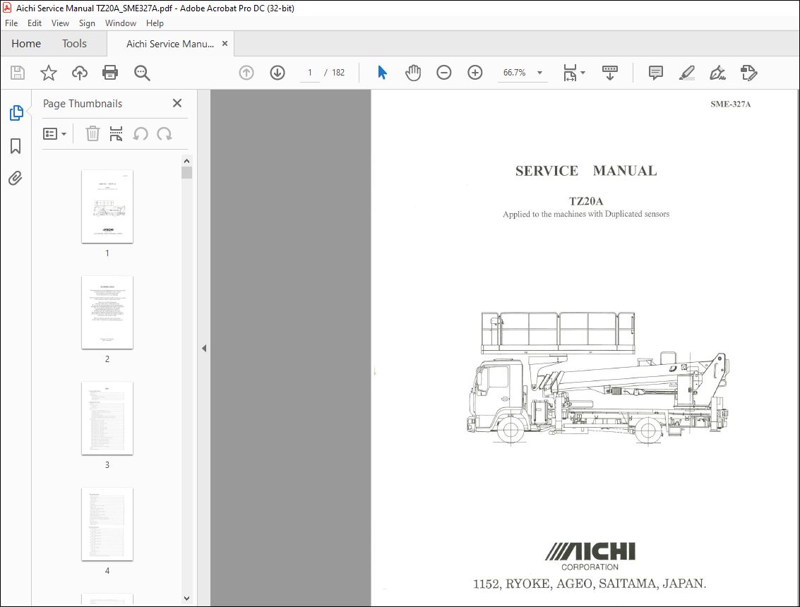
Aichi TZ20A SERVICE MANUAL SME-327A – PDF DOWNLOAD
This manual describes correct adjustments and servicing procedures
for TZ20A AERIAL PLATFORM in order to ensure
the most effective use of superb performance
and excellent features for your satisfaction.
Read this manual carefully and understand the descriptions correctly
before making any repairs or maintenance works.
Always be sure of the following items
when performing repairs or maintenance works.
• Use only the spare parts approved by the manufacturer,
particularly for load-supporting and safety-related components.
• Do not make any modifications to the machine
without obtaining the manufacturer’s approval.
The design check, the manufacturing check as well as
the practical test should be conducted by the approved agent,
if the modification which would affect the stability, strength or
performance of the machine is made.
Please, note that the numerical values in this manual
may be subject to change due to engineering improvement!
TABLE OF CONTENTS:
Aichi TZ20A SERVICE MANUAL SME-327A – PDF DOWNLOAD
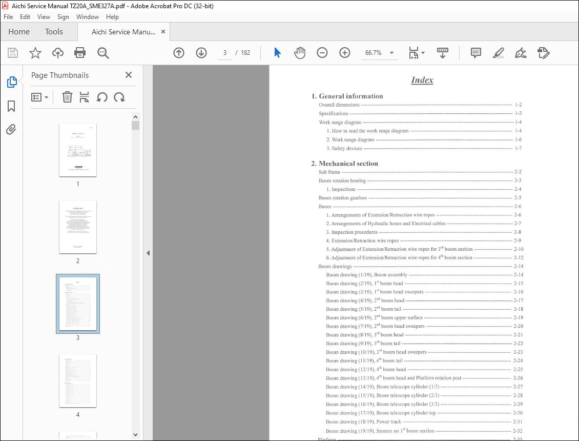
1. General information
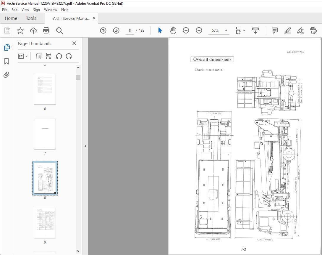
Overa1 dimensions I 2
Specifications I 3
Work range diagram 1 4
I. How to read the work range diagram 1 4
2. Work range diagram 1 6
3. Safety devices I 7
2. Mechanical section
Sub frame 2 2
Boom rotation bearing 2 3
1. Inspections 2 4
Boom rotation gearbox 2 5
Boom 2 6
I. Arrangements of Extension/ Retraction wire ropes 2 6
2. Arrangements of Hydraulic hoses and Electrical cables 2 7
3. Inspection procedures 2 8
4. Extension/Retraction wire ropes 2 9
5. Adjustment of Extension/Retraction wire ropes for 3rd boom section 2 1 O
6. Adjustment of Extension/Retraction wire ropes for 4th boom section 2 12
Boom drawings 2 14
Boom drawing ( l /19), Boom assembly 2 14
Boom drawing (2/19), I st boom head 2 15
Boom drawing (3/19), I st boom head sweepers 2 16
Boom drawing ( 4/19), 2nd boom head 2 17
Boom drawing (5/19), 2nd boom tail 2 18
Boom drawing (6/ I 9), 2nd boom upper surface 2 19
Boom drawing (7/19), 2nd boom head sweepers 2 20
Boom drawing (8/19), 3rd boom head 2 2 I
Boom drawing (9/19), 3rd boom tail 2 22
Boom drawing ( I 0/19), 3rd boom head sweepers 2 23
Boom drawing ( 11/ 19), 4th boom tail 2 24
Boom drawing ( 12/19), 4th boom head 2 25
Boom drawing ( 13/19), 4th boom head and Platform rotation post 2 26
Boom drawing ( 14/ I 9), Boom telescope cylinder ( I /3) 2 27
Boom drawing (15/19), Boom telescope cylinder (2/3) 2 28
Boom drawing ( 16/ 19), Boom telescope cylinder (3/3) 2 29
Boom drawing ( 17 / 19), Boom telescope cylinder top 2 30
Boom drawing ( 18/ 19), Power track 2 3 I
Boom drawing ( I 9/ I 9), Sensors on I st boom section 2 32
PI at form 2 3 3
Platform rota ti on gearbox 2 34
3. Hydraulic section
H ydrau I ic o i I reservoir 3 2
High pressure I ine filter 3 3
Last chance filter 3 4
Outrigger con tro I va Ive 3 5
Ma in contro I va Ive 3 6
S wive I joint 3 8
Jack cy Ii nder 3 1 0
Double pilot check valve for Jack cylinder 3 1 I
Outrigger cy Ii nder 3 13
Pilot check valve for Outrigger cylinder 3 14
Boom elevation cylinder 3 15
Double holding valve for Elevation cylinder 3 16
Boom telescope cylinder 3 18
Double holding valve for Telescope cylinder 3 19
Platform !eve I ing cylinder 3 21
Double holding valve for Platform leveling cylinder 3 22
Double pilot check valve for Platform leveling cylinder 3 23
Stop va Ive 3 24
Boom rotation motor 3 2 5
Platform rotation motor 3 2 6
Emergency pump 3 27
4. Electrical section
CPU board (M4 A) 4 2
I . Input / Output characteristics 4 3
CPU box (M2 D) 4 4
I. Input / Output characteristics 4 5
CPU box (M I C 1) 4 6
I. Input / Output characteristics 4 7
CPU box (MI C 2) 4 8
I. Input / Output characteristics 4 9
CPU box (M2E) 4 10
I. Input / Output characteristics 4 11
CPU box (M2A) 4 I 2
I. Input / Output characteristics 4 13
Main Power box 4 14
I . Relay (CR I and CR 2) 4 15
2. Relay ( CR 3 CR 8) 4 16
3. Charge relay 4 17
4. Diode board (PCA 115) 4 18
Upper contro I box 4 19
Re lay board (PCA 13 5) 4 20
Joystick controller (for Elevation and Horizontal control) 4 21
Joystick controller (for Boom telescope, Boom rotation and Platform rotation) 4 22
Foot switch 4 2 3
Lower control box 4 24
Voice alarm board 4 2 6
Contro I select key switch 4 2 8
Boom angle sensor 4 29
Boom/Platform relative angle sensor 4 30
Boom length sensors 4 3 I
Load sensor ( for Elevation cy I inder) 4 32
Load sensor ( for Leveling cylinder) 4 33
Load sensor AMP 4 3 4
Pressure sensors 4 3 5
Slip ring and Boom rotation sensor 4 36
Boom rotation sensor 4 3 8
Boom rotation sensing limit switches 4 39
Slip ring and Platform rotation sensor 4 40
Platform rotation sensor 4 4 2
Outrigger extension sensors 4 4 3
Outrigger extension indicator 4 44
PI atf orm ti It sensor 4 4 5
Proximity switch 4 46
Extension wire rope failure limit switches ····· 4 47
Boom fu II retraction I imit switch 4 48
Inter I oc k sys tern 4 4 9
Storage posture sensing system 4 5 0
Error code and their countermeasures 4 51
5. Electric circuit for individual system
Engine start and stop system 5 2
Boom elevation / Horizontal contro I system 5 3
Boom telescope / Ve11ical control and Storage sensing system 5 4
Boom rota ti on system 5 5
Platform rotation and Interlock system 5 6
Platform leveling and Platform level adjust system 5 7
Boom auto storage system 5 8
Load moment Ii miter 5 9
Interference I im it system 5 1 0
Emergency pump system 5 11
Accelerator, Panel light and Work light system 5 12
6. Inspections and Adjustments
Inspection procedures of Load moment limiter 6 2
I. Inspection of Outrigger extension indicator 6 3
2. Inspection of work radius 6 4
3. Inspection of Boom rotation limit angle 6 6
1 ns pect ion data sheet 6 7
7. Appendix
Hydra u Ii c circuit diagram 7 2
Locations of Hydrau I ic components 7 3
Electrica I circuit diagram (Platform) 7 4
Electrical circuit diagram (Turntable) 7 5
Electrical circuit diagram (Sub frame) 7 6
Electrical wiring chart (Platform) 7 7
Electrical wiring chart (Platform rotation post) 7 8
Electrical wiring chart (Turntable) 7 9
Electrical wiring chart (Sub frame) 7 1 O
Electrical wiring chart (Chassis) 7 11
Locations of Electrical components 7 12
Tightening torque standard 7 13
8. Inspection manual
Dai I y inspection procedures 8 2
Daily inspection check sheet 8 4
Procedures of Periodical inspections 8 6
Withstand voltage tests 8 11
Function tests 8 11
Periodical inspection check sheet 8 12
Withstand voltage tests check sheet 8 14
Function tests check sheet 8 14
Major alterations and repairs 8 15
VIDEO PREVIEW OF THE MANUAL:
PLEASE NOTE:
- This is the SAME MANUAL used by the dealerships to diagnose your vehicle
- No waiting for couriers / posts as this is a PDF manual and you can download it within 2 minutes time once you make the payment.
- Your payment is all safe and the delivery of the manual is INSTANT – You will be taken to the DOWNLOAD PAGE.
- So have no hesitations whatsoever and write to us about any queries you may have : heydownloadss @gmail.com
I.G


