

1991 GMC Light Duty Truck Fuel And Emissions Service Manual – PDF DOWNLOAD
DESCRIPTION:
1991 GMC Light DutyT ruck Fuel And Emissions Service Manual – PDF DOWNLOAD
FOREWORD
This Service Manual replaces Section 6C and 6E for 2.5L, 2.8L, 4.3L, 5.0L, 5.7L, and 7.4L gasoline engines with throttle body injection and supplements the following shop manuals:
• X-9132 10-30 Series R-V-P Light Duty Truck Service Manual
• X-9129 10 Series S-T Light Duty Truck Service Manual
• X-9130 10 Series M-Van Light Duty Truck Service Manual
• X-9131 10-30 Series C-K Light Duty Truck Service Manual
• X-9157 10-30 Series G Light Duty Truck Service Manual This manual includes the general description of a system, diagnosis and on-vehicle service procedures for the fuel control and emissions used on light duty truck with a throttle body injection fuel control system. Wiring diagrams for the above vehicles are also published in a separate “Truck Wiring Diagram” booklet. This manual should be kept in a handy place for ready reference. If properly used, it will meet the needs of technicians and vehicle owners.
CAUTION:
- These vehicles contain some parts dimensioned in the metric system as well as in the customary system. Some fasteners are metric and are very close in dimension to familiar customary fasteners in the inch system. It is important to note that, during any vehicle maintenance procedures, replacement fasteners must have the same measurements and strength as those removed, whether metric or customary.
- (Numbers on the heads of metric bolts and on surfaces of metric nuts indicate their strength. Customary bolts use radial lines for this purpose, while most customary nuts do not have strength markings.) Mismatched or incorrect fasteners can result in vehicle damage or malfunction, or possibly personal injury.
- Therefore, fasteners removed from the vehicle should be saved for re-use in the same location whenever possible. Where the fasteners are not satisfactory for re-use, care should be taken to select a replacement that matches the original. For information and assistance, see your authorized dealer. NOTICE: No part of this publication may be reproduced, stored
CAUTION:
- To reduce the chance of personal injury and/or property damage, the following instructions must be carefully observed. Proper service and repair are important to the safety of the service technician and the safe, reliable operation of all motor vehicles. If part replacement is necessary, the part must be replaced with one of the same part number or with an equivalent part.
- Do not use a replacement part of lesser quality. The service procedures recommended and described in this service manual are effective methods of performing service and repair. Some of these procedures require the use of tools specially designed for the purpose. Accordingly, anyone who intends to use a replacement part, service procedure or tool, which is not recommended by the vehicle manufacturer, must first determine that neither his safety nor the safe operation of the vehicle will be jeopardized by the replacement part, service procedure or tool selected.
- It is important to note that this manual contains various Cautions and Notices that must be carefully observed in order to reduce the risk of personal injury during service or repair, or the possibility that improper service or repair may damage the vehicle or render it unsafe. It is also important to understand that these “Cautions” and “Notices” are not exhaustive, because it is impossible to warn of all the possible hazardous consequences that might result from failure to follow these instructions.
GENERAL
- All engines in this manual have a Computer Command Control system, with Electronic Control Module (ECM), or a Powertrain Control Module (PCM) to control the Throttle Body Injection (TBI) fuel system. The ECM/PCM varies the air/fuel ratio. In addition, the ECM/PCM controls the ignition timing system as well as other emission control systems such as the exhaust gas recirculation system.
- It is important to review the emission sections and ECM/PCM wiring diagrams for a specific engine to determine what is controlled by the ECM/PCM and what systems are non-ECM/PCM controlled.
- • This section has a brief description of systems used to control fuel and emissions. • Abbreviations that are used in driveability and emissions are listed at the end of the manual.
- • Wiring harness service information, for harnesses used with the ECM/PCM, is also provided in the computer command control section. • Special tools used to diagnose and repair a system are illustrated at the end of the manual. VISUAL/PHYSICAL UNDERHOOD INSPECTION One of the most important checks that must be done as part of any diagnostic procedures or finding the cause of an emissions test failure, is a careful visual/physical underhood in sp ection . This can often lead to fixing a problem without further steps.
- Inspect all vacuum hoses for correct routing, pinches, cuts, or disconnects. Be sure to inspect hoses that are difficult to see beneath the a ir cleaner, compressor, generator, etc. Inspect all the wires in the engine compartment for correct and good connections, burned or chafed spots, pinched wires, or contact with sharp edges or hot e x h au s t manifolds. This visual/physical inspection is very important. It must be done carefully and thoroughly.
TABLE OF CONTENTS:
1991 GMC Light DutyT ruck Fuel And Emissions Service Manual – PDF DOWNLOAD
GENERAL ……………………………………………………… 1
VISUAI7PHYSICAL UNDERHOOD INSPEC. . . . 1
BASIC ELECTRIC CIRCUITS ………………………… ….. 1
EMISSIONS ………………………………………………. ….. 1
MAINTENANCE S C H ED U L E ………………………… ….. 1
VEHICLE EMISSION CONTROL
INFORMATION LABEL …………………………… ….. 1
SECTION DESCRIPTION ………………………………….. 1
Driveability Symptoms ………………………… ….. 1
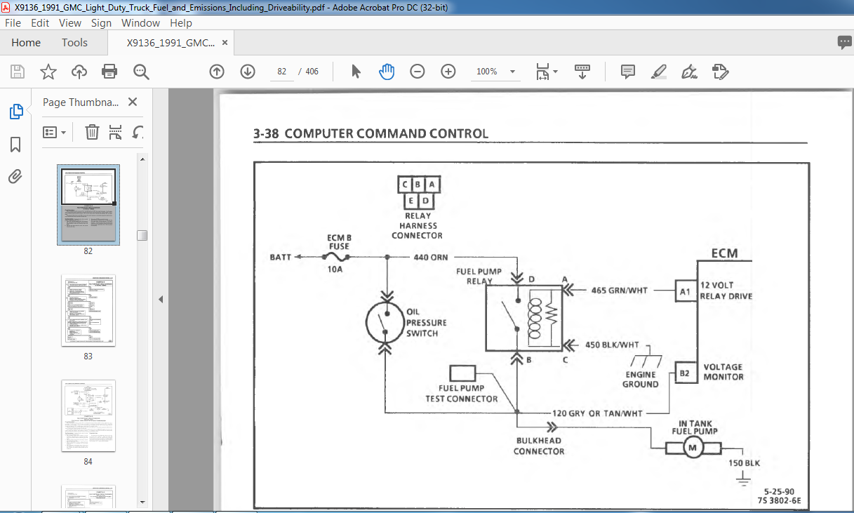
Computer Command Control
(Using “Scan” Tool Diagnosis) ………….. ….. 1
Fuel Control System ……………………………… ….. 1
Evaporative Emission Control ……………………. 1
Ignition/Electronic Spark Timing ………….. ….. 1
Electronic Spark Control …………………………… 1
Air Management ………………………………….. ….. 1
Exhaust Gas Recirculation ……………………. ….. 1
Torque Converter Clutch and Manual
Transmission Shift Light Control ……….. ….. 1
Positive Crankcase Ventilation (PCV) . . . . 1-4
Thermostatic Air Cleaner (THERMAC) . . . 1-4
Special T o o l s ……………………………………………….1-4
Abbreviations ………………………………………….. ..1-4
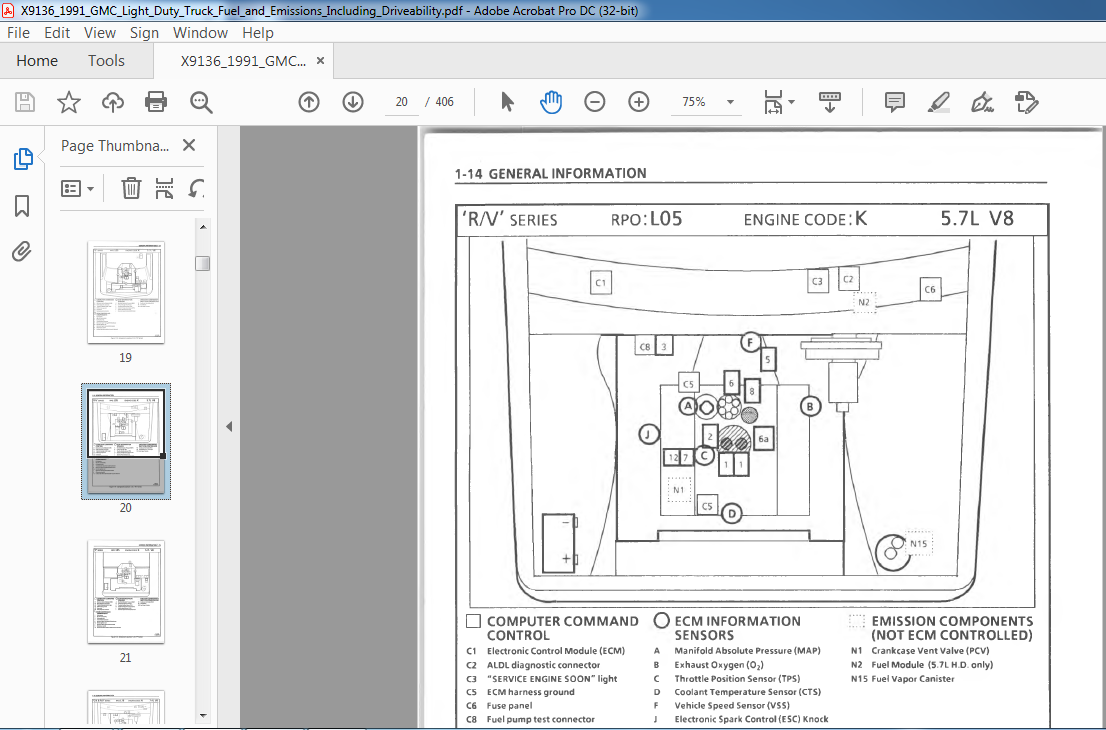
COMPONENT LOCATIONS ……………………………..1-4
2.5 L-S Series …………………………………………….1-5
2 .8 L -S Series …………………………………………….1-6
4.3 L – S/T Series ……………………………………….. ..1-7
4.3L-C/K Series ……………………………………….. ..1-8
4.3L – G Series ……………………………; …………….1-9
4.3L – M, L Series …………………………………….. ..1-10
4.3L-PSeries ………………………………………….. ..1-11
5.0L/5.7L-OK Series ……………………………….. ..1-12
5.7L-G Series ………………………………………….. ..1-13
5.7L – R/V Series ……………………………………….. ..1-14
5.7L-PSeries ………………………………………….. ..1-15
7.4L – OK & R/V Series ……………………………….. 1-16
7 .4L-G Series ………………………………………….. .. 1-17
7.4L-PSeries ………………………………………….. ..1-18
VIDEO PREVIEW OF THE MANUAL:
IMAGES PREVIEW OF THE MANUAL:
PLEASE NOTE:
- This is the SAME exact manual used by your dealers to fix your vehicle.
- The same can be yours in the next 2-3 mins as you will be directed to the download page immediately after paying for the manual.
- Any queries / doubts regarding your purchase, please feel free to contact [email protected]
S.M


Kasen –
Helpful