

Workhorse W Series Truck Shop Manual 2010 – 2012
FILE DETAILS:
LANGUAGE:ENGLISH
PAGES:1650+
DOWNLOADABLE:YES
FILE TYPE:PDF
VIDEO PREVIEW OF THE MANUAL:

IMAGES PREVIEW OF THE MANUAL:

DESCRIPTION:
Workhorse W Series Truck Shop Manual 2010 – 2012
GENERAL INFORMATION OBJECTIVES OF THIS SECTION:
- This section is intended to provide information regarding the safety warnings provided on the 2007 W Series Workhorse chassis. Be sure to fully understand all instructions and procedures before beginning to service components. Observe all Caution and Warning safety alerts that precede instructions or procedures.
- These alerts help to avoid damage to components, serious personal injury, or both. Follow all established maintenance and service, installation, and diagnostics guidelines. Use special tools when required to help avoid serious personal injury and damage to components.
GENERAL PRECAUTIONS :
Read and understand all of the safety precautions and warnings before performing any repair. This list contains the general safety precautions that must be followed to provide personal safety. Special safety precautions are included in the procedures when they apply.
TABLE OF CONTENTS:
Workhorse W Series Truck Shop Manual 2010 – 2012
GENERAL INFORMATION 4
Objectives Of This Section 4
Safety Alerts and Supplemental Information 4
WCC Product and Service Information
Access 5
Special Tool / Equipment Reference
Information 5
SAFETY PRECAUTIONS 6
General Precautions 6
Personal Injury Precautions 6
Environmental Precautions 9
TORQUE SPECIFICATIONS 9
SPECIFICATIONS 4
Fastener Tightening Specifi cations 4
Special Tool and Equipment List 4
Refrigerant Oil Specifi cations 6
COMPONENT LOCATOR 6
CONNECTOR END VIEWS 7
DESCRIPTION AND OPERATION 11
A/C System Description 11
Air Distribution System Description 11
Refrigeration System Description 11
Heater System Description12
Odor Description 12
Handling Refrigerant R-134a13
Handling Compressor Oil 14
Handling of Refrigerant Lines and Fittings 14
Maintaining Chemical Stability 15
Thermal Expansion Valve Description 15
Evaporator Description 16
Condenser Description 16
Heater Core Description 16
Receiver/Dryer Description 17
Compressor Description 17
Control Assembly Description 17
Relays and Sensors Description 17
Auxiliary Engine Coolant Fan A/C Pressure
Switch 17
A/C Compressor High Pressure Cutoff Switch 17
A/C Compressor Refrigerant Pressure Switch 18
A/C Compressor Relay18
DIAGNOSTIC INFORMATION AND PROCEDURES 19
Scan Tool Output Controls 19
PCM Scan Tool Output Controls 19
Scan Tool Data List 20
PCM Scan Tool Data List 81L (L18) 20
Scan Tool Data Defi nitions – Tech II 21
Symptoms – HVAC Systems – Manual 22
Visual/Physical Inspection 22
Intermittent 22
Symptom List 22
HVAC Compressor Clutch Does Not Engage
(Gas Engines) 23
Test Description 23
HVAC Compressor Clutch Does Not Engage
(W42 with 45L (L6I) Engine) 31
Normal Operation 31
Possible Causes31
HVAC Compressor Clutch Does Not Disengage
(Gas Engines) 33
Refrigerant System Checks36
HFC-134a Pressure-Temperature Relationship 37
Leak Testing 37
Service Ports/Access Valves 39
Air Conditioning (A/C) Evaporator Core 39
Air Conditioning (A/C) Compressor Block 40
When Leak Cannot Be Found 40
Odor Diagnosis40
Repair Instructions 42
Odor Correction 42
Refrigerant Recovery and Recharging 43
Compressor Replacement (Gas Engines)44
Compressor Replacement (W42 with 45L (L6I)
Engine) 46
Compressor Oil Balancing (Delphi) 47
Draining 47
Balancing48
Compressor Leak Testing 48
WORKHORSE CUSTOM CHASSIS
Compressor Pressure Relief Valve 51
Compressor Control Switches 51
Compressor Sealing Washers Replacement 52
Compressor Hose Assembly Replacement 53
Evaporator Tube Replacement54
Receiver Dehydrator and Evaporator Hose
Assembly 55
Receiver/Dryer Replacement 56
Compressor Relay Replacement 57
Condenser Fan Replacement 58
Condenser Replacement (Commercial) 58
Condenser Replacement (Motorhome) 59
Heater Hoses Replacement 59
Sealing Washer Replacement 60
GENERAL INFORMATION 4
Objectives Of This Section 4
Safety Alerts and Supplemental Information 4
WCC Product and Service Information Access 4
Special Tool / Equipment Reference Information 4
INTRODUCTION 5
System Confi guration 5
Steering Column And Housing 6
Power Steering Gear 6
Design Of The Power Steering Gear 6
Operation Of The Power Steering Gear 7
Operation Of The Hydraulic Steering Limiter 9
Alignment Of Steering Gear 10
Installation And Assembly 11
Prepare Parts For Assembly 11
Clean Ground Or Polished Parts 12
Clean Rough Parts 12
Dry Cleaned Parts 12
Prevent Corrosion On Cleaned Parts 12
Maintenance 13
External Leaks 13
Filter Change 13
Steering Fluid Change 14
Steering Fluid Filling 14
Steer Axle Performance 15
Installation 15
Prepare Parts For Assembly 15
Inspect Parts 16
LUBRICATION AND MAINTENANCE 16
Schedules And Specifi cations 16
Specifi cation 16
Maintenance 17
Filter Change 17
Steering Fluid Change 17
POWER STEERING PUMP 18
Initial Inspection 18
Inspect Parts 19
Functional Test 19
REMOVAL AND DISASSEMBLY 20
Steering Pump Removal 20
Steering Pump Disassembly 21
Installation 21
Prepare Parts For Assembly 21
Clean Ground Or Polished Parts 22
Clean Rough Parts 22
Dry Cleaned Parts 22
Prevent Corrosion On Cleaned Parts 22
Inspect Parts 22
Fastener Adhesives 22
Adjustments 23
TROUBLESHOOTING 24
FINAL INSPECTION 25
Road Test 25
STEERING COLUMN SERVICE 25
Diagnostic Information And Procedures 25
Symptoms – Steering Wheel and Column 25
Visual/Physical Inspection25
Intermediate Steering Shaft Replacement 25
Steering Steering Wheel And Column 27
Steering Column Accident Damage Inspection 27
Steering Column Trim Covers Replacement 29
Ignition Switch Replacement 30
Ignition Lock Cylinder Replacement 31
Ignition Lock Cylinder Case Replacement 33
Multifunction Switch Replacement 33
Shift Lever Replacement 34
WCC © 2010 Workhorse Custom Chassis — All Rights Reserved
Linear Shift Assembly Replacement 35
Tilt Lever Replacement 37
Steering Wheel Replacement 37
Tilt Spring Replacement 37
Turn Signal Cancel Cam and Upper Bearing Inner
Race Replacement 38
Fastener Tightening Specifi cations 4
Wheel Alignment Specifi cations 4
Tire/Wheel Runout Specifi cations 4
INTRODUCTION 5
Objectives Of This Section 5
Description and Operation 5
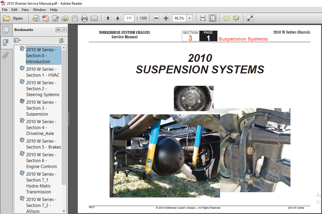
SUSPENSION SYSTEM DESCRIPTION 6
Suspension System Components 6
Parabolic Leaf Springs 6
Like-Air™ Auxiliary Springs 6
Bilstein® Premium Shock Absorbers 6
Heavy-duty Integral Stabilizer Bar 6
Weight Ratings 8
Gross Vehicle Weight Rating (GVWR) 8
Gross Combination Weight Rating (GCWR) 8
Gross Axle Weight Rating (GAWR) 8
Curb Weight 9
Wet Weight 9
Payload 9
Center of Gravity 9
Weight Distribution 9
Weighing a Coach 10
Proper Loading 13
Loading Conditions and Corrections 13
Wheel Bearing Description and Operation 14
Standard Front Wheel Bearings 14
Timken UniPack Wheel Bearings 14
Tire and Wheels Description and Operation 15
General Description 15
Tire Infl ation Description 15
Tire Chain Usage Description 15
Replacement Tires Description 16
All Seasons Tires Description 17
P-Metric Sized Tires Description 17
Tire Placard Description 18
Wheels Description 18
Wheel Repair Description 18
Wheel Alignment Description 19
Camber Description 19
Caster Description 19
Lead/Pull Description 20
Memory Steer Description 20
Setback Description 20
Toe Description 20
Wander Description 21
Diagnostic Information and Procedures 21
Suspension System Diagnosis 21
Shock Absorber Bench Test (Non-Spiral Groove) 25
Wheel Bearing Diagnosis 25
Tapered Roller Bearing Diagnosis 25
Timken Wheel Bearing Diagnosis 31
Tire and Wheel Diagnosis 31
Preliminary Alignment Inspection 34
Preliminary Alignment Inspection (Front Wheel
Alignment Requirements) 35
Wheel Alignment Procedures 35
REPAIR INSTRUCTIONS 35
Suspension System Repairs 35
Wheel Stud Replacement 35
Front Wheel Hub, Bearing, and Seal Replacement
(Standard Wheel Bearing) 36
Front Wheel Hub, Bearing, and Seal Assembly
Replacement (Timken UniPack) 39
Wheel Bearing Adjustment (Standard Bearings) 40
Wheel Bearing Adjustment 42
Hub Cap Replacement 45
WORKHORSE CUSTOM CHASSIS
WCC © 2010 Workhorse Custom Chassis — All Rights Reserved
Adding Lubricant to the Hub Caps 45
Front Stabilizer Shaft Replacement 45
Rear Stabilizer Shaft Replacement 46
Steering Knuckle/King Pin Replacement 46
Shock Absorber Replacement 50
Like-Air Auxiliary Spring Replacement 51
Front Leaf Spring Replacement 51
Rear Leaf Spring Replacement 53
Front Axle Replacement 55
Tire and Wheel Repairs 56
Tire and Wheel Removal and Installation 56
Tire Mounting and Dismounting 57
Tire Rotation 59
Wheel Alignment Adjustments 60
Front Toe Adjustment 60
FASTENER TIGHTENING SPECIFICATIONS 4
Rear Drive Axle 4
Propeller Shaft Runout Specifi cations 5
Lubrication Specifi cations 6
Rear Wheel Bearing Adjustment Specifi cations 6
Lubrication 7
Universal Joints 7
Center Bearings 7
DESCRIPTION AND OPERATION 8
Propeller Shaft 8
Balancing Information 8
Propeller Shaft Phasing 8
Universal Joints 9
Center Bearing 9
Rear Axle 9
Leak at Front Slip Yoke 11
Roughness or Vibration (Above 35 mph) 11
Roughness or Vibration (General Diagnosis) 12
Ping, Snap, or Click Noise 15
Knock or Clunk Noise 15
Scraping Noise 15
Squeak Noise 16
Shudder on Acceleration at Low Speed 16
Noise Diagnosis 17
Rear Axle 17
External Noise 17
Road Noise 17
Tire Noise 17
Tire Noise Test 18
Engine and Transmission Noises 18
Front Wheel Bearing Noise 18
Body Boom Noise or Vibration 18
Rear Axle Noise 19
Rear Wheel Bearing Noise 19
Differential Side Gear and Pinion Noise 19
Gear Noise 19
Wheel Bearings Diagnosis 21
REPAIR INSTRUCTIONS 26
Propeller Shaft 26
Propeller Shaft Replacement (One-Piece) 26
Two-Piece Propeller Shaft Replacement 27
Three-Piece Propeller Shaft Replacement 28
Center Bearing Replacement 31
Rear Axle (M80 Axles) 32
Ring Gear Removal 34
Servicing Standard Differential Case Assembly 34
Case Disassembly 35
Case Reassembly 35
Drive Pinion Removal 36
Ring & Pinion Gear Assembly Theory 39
Establishing Pinion Gear Depth Using Service Tool
Gages 40
Assembly Of Differential 47
Applying RTV Silicone Gasket Sealer To Cover
Plate 52
Rear Axle (S110, S135/S150 Axles) 52
Yoke Replacement 52
Universal Joints Replacement 53
Axle Shaft Replacement 53
Oil Seal And/Or Bearing Replacement 54
Wheel Stud Replacement 55
Vent Hose Replacement 56
Inspection Before Disassembly 56
Drive Axle Disassemble 56
Axle Housing Inspection 58
Differential Inspection 59
WORKHORSE CUSTOM CHASSIS
Service Manual
WCC 2010 W Series
SECTION
4
PAGE
3 Axle & Driveline
2010 W Series Chassis
TOC
© 2010 Workhorse Custom Chassis — All Rights Reserved
Pinion and Ring Gear Inspection 59
Bearings Inspection 60
Shims Inspection 60
Pinion Depth Adjustment 60
Pinion Depth Adjustment 61
Differential Case Assembly 63
Determining Total Shim Pack Size 63
Pinion Installation 65
Differential to Axle Housing Assemble 66
Backlash Adjustment 68
Adjustments Affecting Tooth Contact 71
Drive Axle Final Assembly 72
Ring Gear and Pinion Tooth Contact Pattern
(Spicer Dana S110 – 118 inch and S135/S150 –
14 Inch) 72
Gear Tooth Contact Pattern Check Procedure 72
Correct Gear Patterns For Gleason Cut Gears 73
Lubricant Change 73
Axle Shaft Replacement (Spicer Dana S110 – 118
inch and S135/S150 – 14 Inch) 74
Pinion Bearings Replacement (Spicer Dana S110 –
118 inch and S135/S150 – 14 Inch)75
Pinion and Ring Gear Replacement (Spicer Dana
S110 – 118 Inch and S135/S150 14 Inch) 78
Differential Replacement (Spicer Dana S110 – 118
inch and S135/S150 – 14 Inch) 81
Differential Carrier Replacement (Spicer Dana
S110 – 118 inch and S135/S150 – 14 Inch) 83
Differential Overhaul (Spicer Dana S110 – 118 inch
and S135/S150 – 14 Inch) 84
Backlash Adjustment (Spicer Dana S110 – 118
inch and S135/S150 – 14 Inch) 85
Rear Hub and Bearing Replacement (Spicer Dana
S110 – 118 inch and S135/S150 – 14 Inch) 86
Axle Replacement (Spicer Dana S110 – 118 inch
and S135/S150 – 14 Inch) 88
Cleaning And Inspection 89
Gear Set Identifi cation (Spicer Dana S110 – 118
inch and S135/S150 – 14 Inch) 90
FASTENER TIGHTENING SPECIFICATIONS 6
BRAKE SYSTEM SPECIFICATIONS 7
BRAKE LATHE SPECIFICATIONS (AMMCO)7
BRAKE LATHE SPECIFICATIONS (ACCU-TURN) 7
INTRODUCTION 8
Objectives Of This Section 8
Description and Operation 8
SERVICE BRAKE SYSTEM DESCRIPTION 8
Service Brake System Components 9
Master Cylinder, Reservoir, and Fluid Level Sensor 9
Hydraulic Brake Boosters 9
Master Cylinder 10
Basic Operation of Hydro-Max™ Booster Assembly
and Master Cylinder 12
Hydraulic Fluids 16
Brake Fluid Tubing, Hoses and Fittings 16
Booster Fluid Tubing, Hoses and Fittings 16
Booster Fluid Source 17
Pedal Stop and Proper Spring Load 17
Hydro-Max™ Brake System Diagnosis 18
Hydro-Boost™ Hydraulic Brake Booster 18
System Description 18
Master Cylinder 18
Reservoir and Cover 18
Power Steering Pump 18
Power Piston and Accumulator 19
Brake Fluid and Brake Fluid Handling 22
Substandard Or Contaminated Brake Fluid 22
Flushing the Brake Hydraulic System 23
Normal Operation Noises 23
BRAKE SYSTEM TESTING 24
External Conditions that Affect Brake Performance 24
Tires 24
Vehicle Loading 24
Front Wheel Bearings 24
Front End Alignment 25
Brake Fluid Leaks 25
Brake Hose And Pipe Inspection 25
DIAGNOSTICS AND TROUBLESHOOTING 26
Service Brake System 26
Master Cylinder Diagnosis 26
Brake Hose and Pipe Diagnosis 26
General Brake System Diagnosis 26
Excessive Pedal Effort 26
Pedal Pulsation (Brake Roughness or Chatter) 27
Leaky Caliper 27
No Braking Effect or Excessive Pedal Travel 27
Brake Noise Diagnosis – Chatter 27
Brake Noise Diagnosis – Scraping 28
Brake Noise Diagnosis – Groan 28
Brake Noise Diagnosis – Rattle 28
Brake Noise Diagnosis – Squeal 28
BRAKE ROTORS 28
Hub and Rotor Assemblies 28
Brake Calipers and Pads 29
Brake Rotor Thickness Variation Check 29
Brake Rotor Lateral Runout Check 29
Brake Rotor Tolerance 30
Bosch Hydraulic Brake Diagnosis 30
Warning Light and Buzzer Do Not Shut Off 31
Booster Backup Pump Runs Continuously 31
Booster Backup Pump Does Not Run 31
Brake Pedal Feels Spongy, Soft or Springy 31
Brake Pedal Feels Very Hard 31
Potential Master Cylinder and Booster Leak Points 31
Brake Drag 32
TOC
WORKHORSE CUSTOM CHASSIS
Service Manual
WCC 2010 W Series
SECTION
5
PAGE
3 Brakes
2010 W Series Chassis
TOC
© 2010 Workhorse Custom Chassis — All Rights Reserved
Antilock Brake System (ABS) Diagnostics 32
MAINTENANCE AND REPAIR 32
Setup Procedures 32
Brake Actuation Linkage – Bell Crank Service 33
Caliper Replacement (Brembo 52mM Caliper) 34
Caliper Removal (Brembo 52mm Caliper) 34
Caliper Installation (Brembo 52mm Caliper) 34
Caliper Replacement (Brembo 68mm Caliper) 35
Caliper Removal (Brembo 68mm Caliper) 35
Caliper Installation (Brembo 68mm Caliper) 35
Brake Caliper Replacement (Bosch ZOH-T Caliper) 36
Brake Caliper Removal 36
Brake Caliper Installation 37
Brake Caliper Replacement
(Meritor Quadraulic Caliper) 39
Brake Pad Replacement 39
Brake Pad Replacement (Brembo 52mm Caliper) 39
Brake Pad Replacement (Brembo 68mm Caliper) 43
Brake Pad Replacement (Bosch ZOH-T Caliper) 44
Brake Pad Replacement
(Meritor Quadraulic Caliper) 45
Bleed Screw Replacement 46
Seal and Dust Boot Replacement
(Brembo 52mm Caliper) 46
Seal and Dust Boot Replacement
(Brembo 68mm Caliper) 49
Seal and Dust Boot Replacement
(Bosch ZOH-T Caliper) 50
Seal and Dust Boot Replacement
(Meritor Quadraulic Caliper) 51
Caliper Piston Replacement (Brembo 52mm Caliper) 52
Caliper Piston Replacement (Brembo 68mm Caliper) 55
Caliper Piston Replacement (Bosch ZOH-T Caliper) 57
Caliper Piston Replacement
(Meritor Quadraulic Caliper) 58
Caliper Guide Pin and Dust Boot Replacement
(52mm Caliper) 60
Caliper Guide Pin and Dust Boot Replacement
(68mm Caliper) 60
Guide Pin and Boot Replacement
(Bosch ZOH-T Caliper) 61
Caliper Mounting Bolt Replacement 62
Brake Rotor Replacement 62
Brake Rotor Removal 62
Brake Rotor Installation 62
Refi nishing Brake Rotors 63
Burnishing the Rotors and Pads 65
PARK BRAKE SYSTEM 65
Lever Actuated Park Brake System Components 66
Automatic Apply Park Brake System Components 66
J72 Park Brake Description 66
Actuator Assembly 70
PARK BRAKE SYSTEM DIAGNOSIS72
Park Brake Does Not Hold 72
Park Brake Will Not Release 73
COMPONENT REPLACEMENT (J72 Park Brake) 74
Park Brake Assembly Replacement 74
Park Brake Actuator Assembly Replacement 75
Park Brake System Diagnostics 76
Park Brake System Check 76
System Adjustment Procedures (Manual Apply
Park Brake) 76
Park Brake Cable Adjustment 76
Park Brake Service (Manual Apply Park Brake) 77
Park Brake Shoe Replacement 77
Park Brake Pedal Replacement 78
Park Brake Lever Replacement 79
WORKHORSE CUSTOM CHASSIS
Service Manual
WCC 2010 W Series
SECTION
5
PAGE
4 Brakes
2010 W Series Chassis
TOC
© 2010 Workhorse Custom Chassis — All Rights Reserved
Park Brake Pull Switch Replacement 81
Park Brake Cable Replacement (Pedal Type) 81
Park Brake Cable Replacement (Lever Type) 82
Park Brake Drum Replacement 82
Park Brake Drum Backing Plate Replacement 84
Automatic Apply Park Brake Assembly Replacement 84
Automatic Apply Park Brake Pump/Reservoir
Assembly Replacement 85
ANTILOCK BRAKE SYSTEM (ABS) 86
Antilock Brake System (ABS) Components 87
ABS Electronic Control Unit (ECU) 87
Modulator Assembly 87
Wheel Speed Sensors 88
Sensor Spring Clip 88
Tooth Wheel 88
ABS Indicator Lamp 89
ABS Diagnostic Procedures 89
System Diagnostics 89
Valve, Pump and Retarder Relay Activation 91
Retarder Relay Activation on WABCO Antilock
Brake System 91
Reset Memorized 92
Fault Information Screen 93
ABS Indicator Lamp Activation 93
Standard System Testing 94
System Requirements and Component Tests 94
Standard Component Testing 96
Component Removal and Installation 100
Sensors 100
Wheel Speed Sensor Replacement — Front Axle 100
Wheel Speed Sensor Replacement — Rear Axle 101
Modulator Assembly 102
ABS Brake Bleeding Procedures 103
General 103
Pressure Fill and Bleed 104
System Requirements 107
TOOLBOX™ Start-up 108
Hydraulic ABS 109
Component Tests 110
MERITOR WABCO FAULT CODES 113
DIAGNOSTIC TROUBLE CODES 124
DTC P0608 124
DTC P0609 127
SPECIFICATIONS 7
Fastener Tightening Specifi cations 7
48/60L Engine Fastener Tightening Specifi cations 7
81L Engine Fastener Tightening Specifi cations 7
Ignition System Specifi cations 8
48/60L Ignition System Specifi cations 8
81L Ignition System Specifi cations 8
Altitude vs Barometric Pressure 9
Temperature vs Resistance 10
Diagnostic Trouble Code (DTC) Type Defi nitions 11
Emissions Related DTCs 11
Non-Emissions Related DTCs 12
Diagnostic Trouble Code (DTC) Types 13
48/60L Engine Diagnostic Trouble Code (DTC)
Types 13
81L Engine Diagnostic Trouble Code (DTC) Types 16
DESCRIPTION AND OPERATION 19
Powertrain Control Module Description 19
Powertrain Control Module Function 20
Malfunction Indicator Lamp (MIL) Operation 20
Throttle Actuator Control (TAC) System Description 24
Evaporative Emission Control System Description 27
Purge Solenoid Valve Leak Test 28
Check Gas Cap Message 28
Electronic Ignition (EI) System Description 30
Knock Sensor (KS) System Description 32
Sensor Description 32
Air Intake System Description 33
DIAGNOSTIC INFORMATION AND PROCEDURES 34
48L and 60L Engine Diagnostics 34
Diagnostic Starting Point – Engine Controls 34
Scan Tool Data List 34
Scan Tool Data Defi nitions 40
Scan Tool Output Controls 55
DTC P0030 or P0050 58
DTC P0036 or P0056 (w/48L) 64
DTC P0036 or P0056 (w/60L) 70
DTC P0053 or P0059 76
DTC P0054 or P0060 (w/48L) 83
DTC P0054 or P0060 (w/60L) 90
DTC P0068 97
DTC P0101 102
DTC P0102 110
DTC P0103 120
DTC P0106 126
DTC P0107 132
DTC P0108 137
DTC P0112 142
DTC P0113 146
DTC P0116 151
DTC P0117 159
DTC P0118 163
DTC P0120 168
DTC P0128 178
DTC P0131 or P0151 183
DTC P0132 or P0152 189
DTC P0133 or P0153 197
DTC P0134 or P0154 204
DTC P0135 or P0155 211
DTC P0136 or P0156 217
DTC P0137 or P0157 226
DTC P0138 or P0158 234
DTC P0140 or P0160 241
DTC P0141 or P0161 (w/48L) 248
DTC P0171 or P0174 260
DTC P0172 or P0175 267
TOC
WORKHORSE CUSTOM CHASSIS
Service Manual
WCC 2010 W Series
SECTION
61
PAGE
3 Engine Controls
2010 W Series Chassis
TOC
© 2010 Workhorse Custom Chassis — All Rights Reserved
DTC P0200 274
DTC P0220 279
DTC P0230 288
DTC P0300 293
DTC P0315 300
DTC P0325 304
DTC P0327 or P0332 307
DTC P0335 312
DTC P0336 318
DTC P0341 324
DTC P0342 329
DTC P0343 335
DTC P0351-P0358 341
DTC P0420 or P0430 346
DTC P0442 353
DTC P0443 356
DTC P0446 361
DTC P0449 369
DTC P0452 382
DTC P0453 387
DTC P0454 392
DTC P0455 395
DTC P0641 415
DTC P0650 420
DTC P0651 426
DTC P1125 431
DTC P1133 or P1153 436
DTC P1134 or P1154 443
DTC P1380 450
DTC P1381 453
DTC P1516 456
DTC P2101 463
DTC P2108 470
DTC P2120 473
DTC P2121 482
DTC P2125 489
DTC P2135 497
DTC P2138 504
DTC P2636 508
DTC P2A01 or P2A04 516
DTC U0107 525
81L Engine Diagnostics 534
Scan Tool Data List 534
Scan Tool Data Defi nitions 540
Scan Tool Output Controls 558
DTC P0030, P0036, P0050, or P0056 561
DTC P0053, P0054, P0059, or P0060 568
DTC P0054 or P0060 (w/60L) 576
DTC P0068 583
DTC P0101 587
DTC P0102 596
DTC P0103 606
DTC P0106 612
DTC P0107 617
DTC P0108 622
DTC P0112 627
DTC P0113 631
DTC P0116 637
DTC P0117 646
DTC P0118 650
DTC P0120 655
DTC P0128 665
DTC P0131 or P0151 670
DTC P0132 or P0152 677
DTC P0133 or P0153 685
DTC P0134 or P0154 692
DTC P0135, P0141, P0155, or P0161 699
DTC P0137 or P0157 707
WORKHORSE CUSTOM CHASSIS
Service Manual
WCC 2010 W Series
SECTION
61
PAGE
4 Engine Controls
2010 W Series Chassis
TOC
© 2010 Workhorse Custom Chassis — All Rights Reserved
DTC P0138 or P0158 715
DTC P0140 or P0160 723
DTC P0171 or P0174 730
DTC P0172 or P0175 738
DTC P0200 745
DTC P0220 750
DTC P0230 760
DTC P0300 765
DTC P0315 773
DTC P0325 777
DTC P0327 or P0332 781
DTC P0335 786
DTC P0336 793
DTC P0341 799
DTC P0342 805
DTC P0343 811
DTC P0351-P0358 818
DTC P0420 or P0430 823
DTC P0442 831
DTC P0443 839
DTC P0446 844
DTC P0449 852
DTC P0451 857
DTC P0452 866
DTC P0453 871
DTC P0454 877
DTC P0455 880
DTC P0461 891
DTC P0462 894
DTC P0463 898
DTC P0464 903
DTC P0496 905
DTC P0506 or P0507 910
DTC P0522 914
DTC P0523 918
DTC P0601, P0602, P0603, P0604, P0605, P0606,
P0607, P1600, P1621, P1627, P1680, P1681,
P1683, or P2610 922
DTC P0608 927
DTC P0641 931
DTC P0650 936
DTC P0651 942
DTC P0654 947
DTC P0802 951
DTC P1125 956
DTC P1133 or P1153 961
DTC P1134 or P1154 968
DTC P1258 975
DTC P1380 978
DTC P1381 981
DTC P1516 984
DTC P2101 992
DTC P2108 999
DTC P2120 1002
DTC P2121 1011
DTC P2125 1018
DTC P2135 1027
DTC P2138 1034
DTC P2636 1038
DTC P2A01 or P2A04 1046
DTC U0107 1056
DIAGNOSTIC STARTING POINT – ENGINE
COOLING 1065
DTC P0480 or P0481 1066
DTC P1258 1072
ENGINE COOLING 1074
Symptoms – Engine Cooling 1074
Thermostat Diagnosis 1083
WORKHORSE CUSTOM CHASSIS
Service Manual
WCC 2010 W Series
SECTION
61
PAGE
5 Engine Controls
2010 W Series Chassis
TOC
© 2010 Workhorse Custom Chassis — All Rights Reserved
Coolant Heater Inoperative (Diesel) 1084
Coolant Heater Inoperative (Gasoline) 1085
Circuit/System Testing 1086
Pressure Cap Testing 1089
Cooling System Leak Testing 1090
Fan Clutch Diagnosis 1091
ENGINE ELECTRICAL 1095
Diagnostic Starting Point – Engine Electrical 1095
Scan Tool Data Defi nitions 1096
DTC P0562 1097
DTC P0563 1101
DTC P0615 1104
Symptoms – Engine Controls 1108
Hard Start 1112
Surges/Chuggles 1114
Lack of Power, Sluggishness, or Sponginess 1117
Detonation/Spark Knock 1121
Hesitation, Sag, Stumble 1123
Cuts Out, Misses 1126
Poor Fuel Economy 1130
Poor Fuel Fill Quality 1134
Rough, Unstable, or Incorrect Idle and Stalling 1136
Dieseling, Run-On 1140
Backfi re 1141
Malfunction Indicator Lamp (MIL) Diagnosis 1144
Engine Cranks but Does Not Run 1146
Ignition Relay Diagnosis 1151
Fuel Pump Electrical Circuit Diagnosis 1160
Fuel System Diagnosis 1167
Fuel Injector Solenoid Coil Test 1173
Fuel Injector Balance Test with Special Tool 1176
Fuel Injector Balance Test with Tech 2 1182
Restricted Exhaust 1186
REPAIR INSTRUCTIONS 1189
48L and 60 L Engines 1189
Powertrain Control Module Replacement 1189
Throttle Actuator Control (TAC) Module
Replacement 1190
Crankshaft Position System Variation Learn 1191
Engine Coolant Temperature (ECT) Sensor
Replacement 1192
Mass Airfl ow Sensor/Intake Air Temperature
(MAF/IAT) Sensor Replacement 1193
Manifold Absolute Pressure Sensor
Replacement 1195
Heated Oxygen Sensor Replacement 1196
Accelerator Pedal Position Sensor
Replacement 1197
Throttle Body Assembly Replacement 1199
Throttle Body Cleaning 1201
Fuel Pressure Relief 1201
Fuel Pressure Gage Installation and Removal 1202
Metal Collar Quick Connect Fitting Service 1203
Plastic Collar Quick Connect Fitting Service 1206
Fuel Tank Pressure Sensor Replacement 1208
Fuel Level Sensor Replacement (48L and 60L
Engines) 1208
Fuel Sender Assembly Replacement (48L and
60L Engines) 1209
Fuel System Cleaning 1211
Fuel Injection Fuel Rail Assembly Replacement
(48L and 60L Engines) 1213
Fuel Injector Replacement 1218
Fuel Injector Cleaning 1221
Evaporative Emission Canister Purge Solenoid
Valve Replacement 1223
WORKHORSE CUSTOM CHASSIS
Service Manual
WCC 2010 W Series
SECTION
61
PAGE
6 Engine Controls
2010 W Series Chassis
TOC
© 2010 Workhorse Custom Chassis — All Rights Reserved
Evaporative Emission Hoses/Pipes Replacement
– Engine 1225
Evaporative Emission (EVAP) Canister
Replacement 1226
Evaporative Emission System Cleaning 1226
Ignition Coil Replacement 1227
Spark Plug Wire Inspection 1228
Spark Plug Wire Replacement 1229
Spark Plug Inspection 1230
Spark Plug Replacement 1232
Crankshaft Position Sensor Replacement 1233
Camshaft Position Sensor Replacement 1234
Knock Sensor Replacement 1235
81L Engines 1237
Powertrain Control Module Replacement 1237
Throttle Actuator Control (TAC) Module
Replacement 1238
Crankshaft Position System Variation Learn 1239
Engine Coolant Temperature Sensor
Replacement 1240
Mass Airfl ow Sensor/Intake Air Temperature
Sensor Replacement 1242
Manifold Absolute Pressure Sensor Replacement 1243
Heated Oxygen Sensor Replacement 1244
Accelerator Pedal Position Sensor Replacement 1245
Throttle Body Assembly Replacement 1247
Throttle Body Cleaning 1248
Fuel Pressure Relief 1249
Fuel Pressure Gage Installation and Removal 1249
Metal Collar Quick Connect Fitting Service 1250
Plastic Collar Quick Connect Fitting Service 1252
Fuel Tank Draining 1254
Fuel Tank Pressure Sensor Replacement 1255
Fuel Level Sensor Replacement 1255
Fuel Sender Assembly Replacement 1256
Fuel System Cleaning 1258
Fuel Injection Fuel Rail Assembly Replacement 1258
Fuel Pulse Dampener Replacement 1262
Fuel Injector Replacement 1263
Fuel Injector Cleaning 1264
Evaporative Emission Canister Purge Solenoid
Valve Replacement 1266
Evaporative Emission Hoses/Pipes Replacement
– Engine 1268
Evaporative Emission System Cleaning 1269
Ignition Coil Replacement 1270
Spark Plug Wire Inspection 1271
Spark Plug Wire Replacement 1272
Spark Plug Inspection 1272
Spark Plug Replacement 1275
Crankshaft Position Sensor Replacement 1276
Camshaft Position Sensor Replacement 1279
Knock Sensor 1 Replacement 1280
Knock Sensor 2 Replacement 1281
SPECIFICATIONS 6
Fastener Tightening specifi cations 6
Fluid Capacity Specifi cations 6
Transmission General Specifi cations 6
Transmission Fluid Temperature (TFT) Sensor
Specifi cations 7
Range Reference 8
Shift Solenoid Valve State and Gear Ratio 9
Transmission Fluid Pressure Manual Valve
Position Switch Logic 9
Transmission Range Switch Logic 9
Line Pressure 9
Component Resistance 10
SPECIAL TOOLS 10
INTRODUCTION 13
Objectives Of This Section 13
Description and Operation14
Transmission General Information 14
Transmission Identifi cation Information 15
Defi nitions and Abbreviations 15
Throttle Positions15
Shift Condition Defi nitions 15
Noise Conditions 16
Drive Link Noise 16
Final Drive Noise 16
Planetary Gear Noise 16
Pump Noise 16
Torque Converter Noise 16
Transmission Abbreviations 17
Transmission General Description 17
Transmission Component and System
Description 18
Transmission Adaptive Functions 18
Clearing Transmission Adaptive Pressure (TAP) 19
Transmission Indicators and Messages 19
Electronic Component Description 20
Torque Converter Clutch Solenoid Valve 20
Pressure Control Solenoid Valve 20
1-2 Shift Solenoid Valve 21
2-3 Shift Solenoid Valve 22
Oil Pressure and Circuit Combination Table 24
Automatic Transmission Input Shaft Speed,
Output Shaft Speed Sensors25
Automatic Transmission Fluid Temperature
Sensor 26
Transmission Range Switch 27
Automatic Transmission Inline 20-Way Connector
Description 27
Hydra-Matic Transmission General Diagnosis 29
Diagnostic Starting Point 29
Scan Tool Output Controls 30
Scan Tool Data List 34
Scan Tool Data Defi nitions 37
Diagnostic Trouble Code (DTC) Type
Defi nitions43
Diagnostic Trouble Code (DTC) List/Type 44
DTC P021845
DTC P050249
DTC P050354
DTC P070659
DTC P0711 64
DTC P071269
DTC P071373
DTC P071677
DTC P071782
DTC P071987
WORKHORSE CUSTOM CHASSIS
Service Manual
2010 W Series
SECTION
71
PAGE
3 Transmission — 4L80-E/4L85-E
2010 W Series Chassis
WCC © 2010 Workhorse Custom Chassis — All Rights Reserved
DTC P072493
DTC P073096
DTC P0741101
DTC P0742105
DTC P0748109
DTC P0751 114
DTC P0752 118
DTC P0753122
DTC P0756128
DTC P0757132
DTC P0758136
DTC P0894142
DTC P1810149
DTC P2761156
Symptoms – Automatic Transmission 162
Range Selector Displays Incorrect Range 165
Transmission Fluid Checking 169
Line Pressure Check 172
Road Test 173
Torque Converter Diagnosis 178
Torque Converter Stator 178
Poor Acceleration at Low Speed 178
Poor Acceleration at High Speed 178
Whine Noise 178
Torque Converter Clutch Shudder 179
Torque Converter Evaluation and Diagnosis 180
Flexplate/Torque Converter Vibration Test 181
Isolating Vibration 181
Indexing Torque Converter 182
Noise and Vibration Analysis 183
Engine Coolant/Water in Transmission 183
Fluid Leak Diagnosis 184
General Method184
Powder Method 184
Dye and Black Light Method 184
Find the Cause of the Leak 184
Possible Points of Fluid Leaks 185
Case Porosity Repair 186
Shift Solenoid Leak Test 187
Automatic Transmission Oil Cooler Flushing
and Flow Test J 35944-A 188
Cooler Flow Check and Flushing Steps 188
Tools Required 188
Preparation 189
Back Flush189
Forward Flush 191
Flow Test 192
Clean-up 193
Automatic Transmission Oil Cooler Flushing
and Flow Test J 45096 193
Cooler Flow Check and Flushing Steps 193
Tools Required 193
Machine Set-up 194
Determine Minimum Flow Rate 196
Minimum Flow Rate in Gallons Per Minute
(GPM) 196
Back Flush Procedure 197
Forward Flush 199
Flow Test 200
Code Recording Procedure 201
Clean-up 201
Automatic Transmission Fluid Leaks 202
High Line Pressure 203
Forward Motion in Neutral 203
Inadequate Lubrication at Low Line or Heavy
Loads203
Inadequate Lubrication 204
Engine Stall in Neutral 204
WORKHORSE CUSTOM CHASSIS
Service Manual
2010 W Series
SECTION
71
PAGE
4 Transmission — 4L80-E/4L85-E
2010 W Series Chassis
WCC © 2010 Workhorse Custom Chassis — All Rights Reserved
Loss of Power204
No Torque in Reverse and Third 204
Transmission Overheats 204
Transmission Overheats at WOT 205
Low Line Pressure205
Engine Starts in Gear 205
Shift Lever Indicates Wrong Gear 205
No Gear Selection 205
Loss of Drive 206
No Park 206
Remains in Park 207
Diffi cult to Shift Out of Park 207
Does Not Stay in Park 207
No Reverse 207
No First Gear – D1 208
No Second Gear – D1 208
No Overrun Braking – D1 208
No Engine Braking – D1 208
No First Gear – D2 208
No Second Gear – D2 208
No Overrun Braking – D2 209
No Engine Braking – D2 209
No Second Gear Engine Braking – D2209
No First Gear – D3 209
No Second Gear – D3 209
No Third Gear – D3 209
No Overrun Braking – D3 210
No Engine Braking – D3 210
No First Gear – D4 210
First Gear Only – D4 210
First and Second Gear Only – D4 210
Second Gear Only – D4 210
Second and Third Gear Only – D4 211
First and Fourth Gear Only – D4 211
Third and Fourth Gear Only – D4 211
No Second Gear – D4 211
No Third Gear – D4 211
No Fourth Gear – D4 212
No Torque Converter Clutch Apply 212
Soft Torque Converter Clutch Apply 213
Torque Converter Clutch (TCC) Slipping 213
Torque Converter Clutch (TCC) Stuck On 213
Incorrect Torque Converter Clutch (TCC) Apply
or Release 214
Converter Ballooning 214
No Torque Multiplication 214
Fluid Foaming214
Noise 215
Engine Stall 215
Vibration 215
Oil Out the Vent Tube 215
No Torque in Second Gear 215
Second Gear Starts 216
Third Gear Starts 216
Fourth Gear Starts216
Erratic Shift Quality216
Transmission Slips 216
Case Extension Bearing/Seal Failed 216
Inaccurate Shift Points 217
Harsh Shifts 217
Harsh Shift D-to-R 217
Harsh Shift 3-to-4 217
Harsh Shift 4 to 3217
Harsh Shift D4 to D3, D2, or D1 218
Soft Shifts 218
Soft Shift into R 218
Soft Shift R to D218
Soft Shift 2 to 1 218
WORKHORSE CUSTOM CHASSIS
Service Manual
2010 W Series
SECTION
71
PAGE
5 Transmission — 4L80-E/4L85-E
2010 W Series Chassis
WCC © 2010 Workhorse Custom Chassis — All Rights Reserved
Transmission Extension Housing Rear Oil Seal
Replacement 246
Transmission Fluid Cooler Hose/Pipe Quick-
Connect Fitting Replacement 247
Transmission Fluid Cooler Hose/Pipe
Replacement 248
Transmission Fluid Draining 249
Transmission Fluid Filter Assembly Removal 250
Transmission Fluid Filter Assembly Installation 250
Transmission Fluid Pan Removal 251
Transmission Fluid Pan Installation 251
Transmission Holding Fixture Installation 252
Transmission Mount Replacement 252
Transmission Replacement 253
Transmission Wire Harness Removal 255
Valve Body and Pressure Switch Replacement 255
Vent Hose 257
Wiring Harness Installation258
Soft Shift 2 to 3 218
Soft Shift 3 to 2 219
Soft Shift D3 to D2219
Delayed Shift 1 to 2 219
No D2 to D1219
No D3 to D2219
REPAIR INSTRUCTIONS 220
Accumulator Housing Replacement 220
Automatic Transmission Fluid and Filter
Replacement 221
Automatic Transmission Range Selector Lever
Cable Bracket Replacement222
Automatic Transmission Range Selector Lever
Cable Replacement 223
Case Extension Assembly Removal225
Case Extension Assembly Installation225
Filler Tube and Seal Replacement 226
Forward Servo Replacement227
Input Shaft Speed Sensor Replacement 228
Manual Shift Shaft Seal Replacement229
Output Shaft Speed Sensor Replacement 230
Park Lock Pawl and Actuator Replacement 231
Park/Neutral Position Switch Adjustment 232
Park/Neutral Position Switch Replacement 233
Pressure Regulator Replacement 235
Range Selector Lever Cable Adjustment 237
Reverse Servo Replacement 239
Speed Sensor Assembly RePlacement241
Torque Converter Assembly Replacement 241
Torque Converter Clutch Valve and Spring
Replacement 242
Torque Converter End Play Inspection 244
Transmission Extension Housing Assembly
Replacement 245
SPECIFICATIONS 7
Fastener Tightening specifi cations 7
Fluid Capacity Specifi cations 7
Fluid Quantities 7
Transmission General Specifi cations 8
Torque Converter Clutch Pressure Control
Solenoid (TCC PCS) Specifi cations 8
Shift Solenoid 1 (SS1), SS2, SS3, and
Modulated Main Pressure (MAIN MOD)
Solenoid Specifi cations 8
Transmission Fluid Temperature (TFT) Sensor
Temperature vs Resistance Specifi cations9
Temperature Versus Resistance (Speed Sensor) 10
Temperature Versus Resistance (Solenoid) 11
Pressure Switch Manifold (PSM) Logic 11
Transmission Internal Mode Switch Logic 12
Solenoid and Clutch Chart (Normal Mode) 12
Solenoid and Clutch Chart (Tow/Haul) 14
Shift Speed (1-2 and 2-3 Shifts) 15
Shift Speed (3-4, 4-5, 5-6 and CT Downshifts) 15
Line Pressure 17
SPECIAL TOOLS 17
Component Locator 23
Automatic Transmission Inline Harness
Connector End View 24
Engine Harness to Transmission27
Torque Converter Clutch/Converter Housing
Assembly Disassembled View 27
Torque Converter Housing, 1-2-3-4-5-6 Clutch
Assembly, and 3rd, 5th, and Reverse Clutch
Components Disassembled View 28
Torque Converter Housing/Oil Pump Cover
Assembly 28
Oil Pump Assembly Disassembled View 29
Oil Pump Cover Assembly Disassembled View 29
Oil Pump Cover/Oil Pump Assembly and
Associated Parts Disassembled View 30
1-2-3-4, 4-5-6 Clutch Assembly Disassembled
View 30
Torque Converter Housing/Automatic
Transmission Case and Associated
Components Disassembled View 31
Automatic Transmission Case Disassembled
View 32
2-6 Clutch/Low and Reverse Clutch
Disassembled View 33
Input Carrier, Intermediate Carrier, and Main
Shaft Disassembled View 34
Input Carier and Ring Gear Assembly
Disassembled View 34
Output Carrier Disassembled View 35
Input Carrier Assembly Disassembled View 35
Intermediate Carrier Assembly Disassembled
View 36
Output Carrier Assembly, Output Shaft, Low and
Reverse Clutch Retrurn Spring Assembly and
Park Pawl Disassembled View 36
Low and Reverse Clutch Piston Housing
Disassembled View 37
Output Carrier Assembly Disassembled View 37
Low and Reverse Clutch Housing Assembly
Disassembled View 38
Control Valve Body Assembly Disassembled
View 39
Shift Valve Body Assembly 40
Main Valve Body Assembly Disassembled
View 41
TOC
WORKHORSE CUSTOM CHASSIS
Service Manual
WCC 2010 W Series
SECTION
72
PAGE
3 Automatic Transmission – Allison
2010 W Series Chassis
TOC
© 2010 Workhorse Custom Chassis — All Rights Reserved
Bearing and Bushing Locations42
Seal Locations 42
Automatic Transmission Internal Connector
End Views 43
Mod Main Pressure Control Solenoid43
Pressure Control Solenoid 1 (PCS1)44
Pressure Control Solenoid 2 (PCS2)44
Pressure Switch Manifold (PSM)45
Shift Solenoid 1 (SS1) 45
Shift Solenoid 2 (SS2) 46
Shift Solenoid 3 (SS3) 46
Torque Converter Clutch Pressure Control
Solenoid (TCC PCS) 47
Transmission Internal Mode Switch 47
Automatic Transmission Input Speed Sensor
(AT ISS) 48
Automatic Transmission Turbine Speed Sensor 48
Transmission Control Module (TCM) 80-Way
Connector 49
Vehicle Speed Sensor (VSS) 50
INTRODUCTION 51
Objectives Of This Section 51
Description and Operation51
Transmission General Information 51
Defi nitions and Abbreviations 51
Throttle Position Defi nitions51
Throttle-Related Shift Condition Defi nitions 52
Shift Condition Defi nitions 52
Noise Conditions 53
Transmission Abbreviations 53
Transmission Identifi cation Information 54
Externally Generated Electronic Interference
(Speed Sensor Signals) 55
Transmission General Description 55
Transmission Component and System
Description 56
Engine/Transmission Connection 56
Torque Converter56
Gear Sets 56
Clutches 56
Hydraulic System 56
Transmission Fluid Filtration 56
Electrohydraulic Control Valve Assembly 57
Remote Oil Cooler Provision 57
Fill Tube/Dipstick Provision 57
Park Pawl 57
Power Take-Off (PTO) Provision 57
Tow/Haul Mode57
Activation 58
Adapt Function 58
Transmission Indicators and Messages 59
NORMAL Inhibits Which Result in a Blinking
PRNDL 59
MALFUNCTIONS Which May Cause a Blinking
PRNDL 59
Conditions Which May Cause a BLANK
PRNDL 59
Electronic Component Description 60
Transmission Control Module 60
Throttle Position/Torque Management 60
Speed Sensors 61
Shift Selector 61
Internal Components 62
Solenoids63
Pressure Switch Manifold 64
Internal Wiring Harness 64
Neutral – Engine Running 65
First Range 68
WORKHORSE CUSTOM CHASSIS
Service Manual
WCC 2010 W Series
SECTION
72
PAGE
4 Automatic Transmission – Allison
2010 W Series Chassis
TOC
© 2010 Workhorse Custom Chassis — All Rights Reserved
Second Range (Without TCC Applied) 71
Second Range (With TCC Applied (Tow-Haul)) 74
Third Range74
Fourth Range 77
Fifth Range 80
Sixth Range 83
Reverse 86
Default Reverse – Limp Home 89
Default Forward – 3rd Range Limp Home 91
Electronic Controlled Shifter (ECS) System 93
Shifter Overview 93
Control Panel Operation 94
Additional System Features: 95
DIAGNOSTIC INFORMATION AND PROCEDURES 96
Diagnostic Starting Point – Automatic
Transmission 96
Scan Tool Data List 96
Scan Tool Data Defi nitions 100
Diagnostic Trouble Code (DTC) Type
Defi nitions104
Type A104
Type B 104
Type C 105
Type X 105
Diagnostic Trouble Code (DTC) List/Type 105
DTC P0218107
DTC P0561111
DTC P0562 115
DTC P0563 118
DTC P0602121
DTC P0613124
DTC P0634127
DTC P0658130
DTC P0659135
DTC P0700139
DTC P0701141
DTC P0703145
DTC P0706149
DTC P0708153
DTC P0711 158
DTC P0712163
DTC P0713168
DTC P0716173
DTC P0717177
DTC P0721181
DTC P0722185
DTC P0726189
DTC P0727193
DTC P0729197
DTC P0731201
DTC P0732205
DTC P0733209
DTC P0734213
DTC P0735217
DTC P0736221
DTC P0741225
DTC P0742229
DTC P0751233
DTC P0752238
DTC P0756243
DTC P0757248
DTC P0761253
DTC P0762258
DTC P0776263
DTC P0777267
DTC P0826271
DTC P0827276
DTC P0828281
WORKHORSE CUSTOM CHASSIS
Service Manual
WCC 2010 W Series
SECTION
72
PAGE
5 Automatic Transmission – Allison
2010 W Series Chassis
TOC
© 2010 Workhorse Custom Chassis — All Rights Reserved
DTC P0842286
DTC P0843291
DTC P0847296
DTC P0848301
DTC P0851 or 0852 306
DTC P0872309
DTC P0873314
DTC P0873319
DTC P0877324
DTC P0878329
DTC P0880334
DTC P0881339
DTC P0882342
DTC P0883345
DTC P0960348
DTC P0962353
DTC P0963357
DTC P0964361
DTC P0966366
DTC P0967371
DTC P0972376
DTC P0973381
DTC P0974386
DTC P0975391
DTC P0976396
DTC P0977401
DTC P0978406
DTC P0979 411
DTC P0980416
DTC P1688421
DTC P1779424
DTC P2670427
DTC P2671432
DTC P2723436
DTC P2724440
DTC P2727445
DTC P2729450
DTC P2730455
DTC P2761460
DTC P2763465
DTC P2764470
Symptoms – Automatic Transmission 475
Functional Test 477
Functional Test Procedure 477
Transmission Fluid Checking 480
Cold Fluid Check 480
Hot Fluid Check 481
Fluid Inspection 481
Line Pressure Check 482
Obtaining Diagnostic Trouble Codes 484
Clutch Test 485
FastLearn Procedure486
Limp Home Mode 488
Road Test 488
Manual Downshifts 492
Manual Range Selection 493
Torque Converter Diagnosis 493
Flexplate/Torque Converter Vibration
Test (81L) 496
Noise and Vibration Analysis 499
Fluid Leak Diagnosis 499
Case Porosity Repair 501
Automatic Transmission Oil Cooler Flushing
and Flow Test 501
Excessive Slippage and Clutch Chatter 506
Fluid Leaks from Fluid Fill Tube and/or Vent 507
Fluid Leaks from Transmission Input507
Fluid Leaks from Transmission Output 508
WORKHORSE CUSTOM CHASSIS
Service Manual
WCC 2010 W Series
SECTION
72
PAGE
6 Automatic Transmission – Allison
2010 W Series Chassis
TOC
© 2010 Workhorse Custom Chassis — All Rights Reserved
Intermittent Buzzing Noise 508
Low Main Line Pressure in All Ranges 509
Low Main Line Pressure in Specifi c Ranges,
Normal Pressure in Other Ranges 509
Low Lubrication Pressure 510
Contaminated Transmission Fluid 510
Excessive Flare – Engine Overspeed on
Wide-Open Throttle 511
High Stall Speeds (Stall in Ranges 1-6) 511
Low Stall Speeds (Stall in Ranges 1-6) 512
Transmission Will Not Make a Specifi c Shift 512
Transmission Will Not Stay In Forward or
Reverse 513
Transmission Will Not Shift to Forward or
Reverse 514
Transmission Overheats 515
Transmission Does Not Shift Properly 516
Abnormal Activities or Responses 516
REPAIR INSTRUCTIONS 517
Transmission Control Module Replacement 517
Transmission Fluid Filter Adapter Replacement 518
Transmission Fluid Cooler Hose/Pipe Connector
Replacement 520
Automatic Transmission Fluid and Filter
Replacement 521
Filler Tube and Seal Replacement 522
Transmission Fluid Cooler Hose/Pipe
Replacement 524
Transmission Heat Shield Replacement 535
Transmission Mount Replacement 536
Transmission Replacement 538
Tools Required 538
Emergency Removal From Park 556
Electronic Shift Controller (ECS) Actuator Initial
Installation 556
Shifter Calibration 561
Calibration Using Shift Shaft Adapter A 561
Calibration Using Shift Shaft Adapter B562
DESCRIPTION AND OPERATION 5
Diagnostic Link Connector Description 5
16-Pin DLC 5
9-Pin DLC 5
Lighting Systems Description 5
Headlamps 5
Daytime Running Lamps 6
Flash-To-Pass 6
Park Lamps 6
Turn Lamps 6
Hazard Lamps 6
Stoplamps 6
Backup Lamps6
Windshield Wiper/Washer System Description 6
LOW or MIST Position 7
HIGH Position7
DELAY Operation 7
Washer Pump 7
Horns Description 8
Cruise Control System Description 8
Wiring Systems Description 8
Schematic Information8
CIRCUIT PROTECTION 11
Fuses 11
Circuit Breakers 12
Fusible Links 13
WIRING REPAIRS 14
Repairing Damaged Wire Insulation14
Wiring Harness Replacement14
Heated Oxygen Sensor (HO2S) Wiring Repairs 14
Diagnosis Using The Wiring Schematics 14
Schematic Icons 14
Connector Reference Zone Numbers 14
Instrument Cluster Description and Operation 15
Test at Turn On 22
Access to Diagnostic Menus and Menu
Operation22
Menu Operation22
Adjusting Display Contrast 23
Restore Default 23
Gauge Backlight 24
Software version24
Part Number 24
Engine hours 24
Max Engine RPM 24
Max Vehicle Speed24
Engine Oil Life Remaining 25
DIAGNOSTIC INFORMATION AND PROCEDURES 26
General Electrical Diagnosis Procedures 26
Basic Knowledge Required 26
Electromotive Force 26
Voltage 26
Resistance26
Ohms 27
Tips for Using an Ohmmeter 27
Ohm’s Law 28
Electrical Current 30
Amperage 30
Ammeter 30
The Diagnostic Process 30
General Electrical Diagnosis 33
Troubleshooting with a Digital Multimeter
(DMM) 33
Measuring Voltage34
Measuring Voltage Drop 35
Measuring Frequency36
TOC
WORKHORSE CUSTOM CHASSIS
Service Manual
WCC 2010 W Series
SECTION
8
PAGE
3 Electrical Systems
2010 W Series Chassis
TOC
© 2010 Workhorse Custom Chassis — All Rights Reserved
Testing for Continuity 36
Testing for Short to Ground 37
Testing for a Short to Voltage 38
Troubleshooting with a Short Finder 39
Troubleshooting with a Test Lamp 39
Probing Electrical Connectors 39
Using Connector Test Adapters 40
Using Fused Jumper Wires 40
Measuring Voltage40
Measuring Voltage Drop 41
Testing for Continuity 41
Testing for Short to Ground 42
Using Connector Test Adapters 43
Intermittents and Poor Connections 43
Testing for Intermittent Conditions and Poor
Connections 43
Testing for Proper Terminal Contact 44
Testing for Proper Terminal Contact in Bussed
Electrical Centers (BEC) 45
Flat Wire (Dock and Lock) Connectors 45
Control Module/Component Voltage and
Grounds45
Temperature Sensitivity 46
Electromagnetic Interference (EMI) and
Electrical Noise46
Inducing Intermittent Fault Conditions 47
Low Temperature Conditions 48
Duplicating Failure Conditions49
Testing for Electrical Intermittents 49
Diagnostic Link Connector Diagnostics 50
Data Link Communications System Check 50
Scan Tool Does Not Communicate with
Components 51
Scan Tool Does Not Communicate with EBCM
(W20/W22) 54
Scan Tool Does Not Communicate with PCM 55
Scan Tool Does Not Communicate with TCM 57
Lighting Systems 60
Courtesy or Dome Lamps Always On 60
Courtesy or Dome Lamps Inoperative61
Instrument Panel Lighting Issues 63
Windshield Wiper/Washer Diagnosis 64
Washer Always On 64
Washers Inoperative 65
Wipers Inoperative – All Modes 67
Wipers Delay Mode Inoperative 68
Wipers High Mode Inoperative 69
Wipers Low or Mist Modes Inoperative 70
Cruise Control Diagnostics 72
Cruise Control System Check 72
Cruise Control Does Not Set or Accelerate 73
Horns 77
Horns Always On 77
Horns Inoperative 78
Adjustable Pedals Diagnosis 81
DTC U1001-U125483
DTC U1300, U1301, or U1305 88
Instrument Cluster Diagnostic Information 89
Cluster Diagnostic 89
Gauge Test 89
Warning Lamps Test 90
LCD Test 90
Backlighting Test 91
Speaker Test 91
Switch Inputs 92
Analog Inputs 92
Frequency Inputs93
WORKHORSE CUSTOM CHASSIS
Service Manual
WCC 2010 W Series
SECTION 8
Troubleshooting the Instrument Cluster 93
Gauges 93
Warning lights 95
Backlighting 97
Misc 98
REPAIR INSTRUCTIONS 104
Wiring Repairs 104
Repairing Damaged Wire Insulation104
Splicing Copper Wire104
Copper wire can be spliced using either splice
clips or splice sleeves104
Splicing Twisted Pair Wiring 108
HO2S Wiring Repairs 108
Headlamp Switch Replacement 109
PLEASE NOTE:
- This is the same manual used by the dealers to diagnose and troubleshoot your vehicle
- You will be directed to the download page as soon as the purchase is completed. The whole payment and downloading process will take anywhere between 2-5 minutes
- Need any other service / repair / parts manual, please feel free to contact [email protected] . We still have 50,000 manuals unlisted


