

Yanmar Marine Gear Kmh40a Kmh50a Kmh50v Service Repair Manual Instant
FILE DETAILS:
LANGUAGE:ENGLISH
PAGES:260
DOWNLOADABLE:YES
FILE TYPE:PDF
VIDEO PREVIEW OF THE MANUAL:

IMAGES PREVIEW OF THE MANUAL:

DESCRIPTION:
Yanmar Marine Gear Kmh40a Kmh50a Kmh50v Service Repair Manual Instant
INTRODUCTION:
This Service Manual gives specific instructions for proper repair on KMH40A transmissions. Please follow the procedures carefully to ensure quality service. Yanmar recommends that you read this Service Manual completely before starting with repairs, as some of the procedures described are rather complex. Along with standard tools, Yanmar recommends the use of special tools necessary to perform repairs correctly. Yanmar products are continuously undergoing improvement.
- This Service Manual has been checked carefully in order to avoid errors. However Yanmar is not liable, for any misrepresentations, errors of description or omissions. Contact an authorized Yanmar marine dealer or distributor for any questions you have regarding this Service Manual.
This Service Manual has been developed for the exclusive use of service and repair professionals such as Yanmar authorized Distributors and Yanmar authorized Dealers. It is written with these professionals in mind and may not contain the necessary detail or safety statements that may be required for a non-professional to perform the service or repair properly and / or safely. Please contact an authorized Yanmar repair or service professional before working on your Yanmar product.
- All information, illustrations and specifications in this manual are based on the latest information available at the time of publishing. The illustrations used in this manual are intended as representative reference views only.
- Moreover, because of our continuous product improvement policy, we may modify information, illustrations, and / or specifications to explain and / or exemplify a product, service, or maintenance improvement. We reserve the right to make any change at any time. Yanmar and are registered trademarks of Yanmar Co., Ltd. in Japan, the United States and / or other countries.
TABLE OF CONTENTS:
Yanmar Marine Gear Kmh40a Kmh50a Kmh50v Service Repair Manual Instant
KMH40A_SM_REV_00_A4_10JAN07.pdf................................................... 3
Table of Contents............................................................. 5
Introduction.................................................................. 7
Revision History.......................................................... 8
Revision Control Table................................................ 8
Safety........................................................................ 9
Safety Precautions........................................................ 12
General Information................................................... 12
Before You Service the Marine Gear.................................... 12
During Servicing...................................................... 12
General Service Information................................................... 17
Safety Precautions........................................................ 18
General Information....................................................... 18
Marine Gear System........................................................ 19
Drive Flow in Shift Lever Position “A”................................ 19
Drive Flow in Shift Lever Position “B”................................ 20
Shifting the Marine Gear.................................................. 21
Marine Gear Specifications................................................ 22
Hydraulic Diagram......................................................... 23
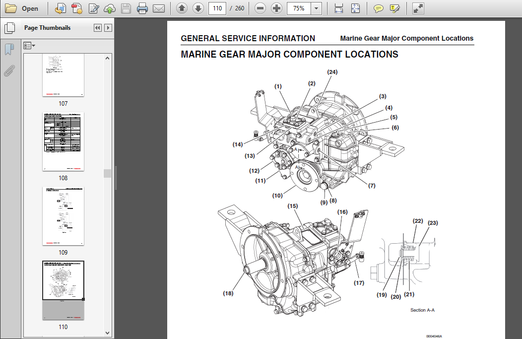
Marine Gear Major Component Locations..................................... 24
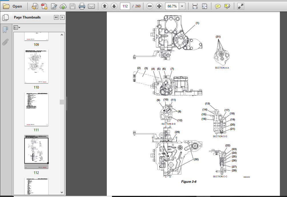
Case Plate Component Location............................................. 26
Shifting Pressure......................................................... 28
Function Test............................................................. 29
Required Tests........................................................ 29
Standard Performance Values....................................... 30
Service....................................................................... 31
Introduction.............................................................. 33
Before You Begin Servicing................................................ 33
Maintenance History....................................................... 36
Special Service Tools..................................................... 37
Measuring instruments..................................................... 40
Standard Tools............................................................ 41
Torque Charts............................................................. 42
Standard Torque Values................................................ 42
Torque Specifications................................................. 42
Sealants and Compounds.................................................... 43
Marine Gear Components.................................................... 44
Case Plate Components..................................................... 46
Marine Gear Sectional View................................................ 48
Clutch Pack Service....................................................... 50
General Service Information........................................... 50
Clean the Marine Gear............................................. 50
Drain the Oil......................................................... 51
Remove the Oil Strainer............................................... 51
Remove the Output Coupling............................................ 52
Remove the Hydraulic Oil Pump......................................... 52
Remove the Case Plate................................................. 53
Remove the Valves..................................................... 53
Remove the Mounting Feet.............................................. 54
Remove the Mounting Flange............................................ 54
Disassemble the Cases................................................. 55
Remove the Shafts and Gears........................................... 55
Remove the Oil Seals.................................................. 56
Remove the Baffle Plate and Oil Suction Cover......................... 56
Remove the Seal Rings................................................. 56
Remove the Tapered Roller Bearings.................................... 57
Remove the Tapered Roller Bearings’ Inner Races................... 57
Remove the Clutch Pack................................................ 58
Remove the Clutch Discs........................................... 58
Remove the Clutch Pistons......................................... 59
Inspect the Bearings.................................................. 60
Inspect the Shafts and Gears.......................................... 60
Inspect the Friction Discs........................................ 60
Inspect the Thrust Collars........................................ 60
Assemble the Input Shaft and Support Shaft............................ 61
Reassemble the Friction Assembly.................................. 61
Assemble the Pinion Gear Assemblies................................... 62
Assemble the Thrust Collars........................................... 62
Assemble the Tapered Roller Bearings onto Input and Support Shafts.... 63
Reassemble the Seal Rings............................................. 63
Reassemble the Tapered Roller Bearing onto Output Shaft............... 64
Inspect the Cases..................................................... 64
Assemble the Oil Suction Cover (If Removed)........................... 64
Assemble the Oil Seals................................................ 64
Assemble the Gear Set into Housing.................................... 65
Final Assembly of Cases............................................... 65
Assembly the Mounting Flange.......................................... 66
Assemble the Valves................................................... 66
Assemble the Case Plate............................................... 67
Install the Oil Strainer.............................................. 67
Install the Hydraulic Oil Pump........................................ 68
Install the Output Coupling........................................... 68
Fill the Marine Gear With Oil......................................... 68
Checking Oil Level.................................................... 68
Gear Shimming Adjustment.................................................. 70
Remove the Bearing Races.............................................. 70
Adjust Gear Backlash.................................................. 70
Adjust Gear Backlash.............................................. 71
Assemble the Tapered Roller Bearing Outer Races into Case B........... 72
Measure Bearing Clearance / Adjusting Bearing Preload................. 73
Adjust Bearing Preload / Play..................................... 73
Adjust Bearing Clearance.......................................... 73
Assemble the Tapered Roller Bearings Outer Races into Case A.......... 74
Trial Run................................................................. 75
Troubleshooting............................................................... 77
Troubleshooting........................................................... 77
Optional Accessories.......................................................... 81
Electric Shift Valve...................................................... 81
Installation of Electric Shift Valve.................................. 81
Electric Shift Valve Wiring........................................... 82
Emergency Operation of Electric Valve................................. 82
Current Production Models......................................... 82
Past Production Models............................................ 83
Mechanical Trolling Valve................................................. 84
Installation of Mechanical Trolling Valve............................. 84
Oil Pressure Adjustment........................................... 84
Electric Trolling Valve................................................... 85
Installation.......................................................... 85
PTO Spline Sleeve and Flange.............................................. 86
Specifications........................................................ 86
Installation of the PTO Spline Sleeve and Flange...................... 86
KMH50A_SM_REV_00_A4_10JAN07.pdf................................................... 89
Table of Contents............................................................. 91
Introduction.................................................................. 93
Revision History.......................................................... 94
Revision Control Table................................................ 94
Safety........................................................................ 95
Safety Precautions........................................................ 98
General Information................................................... 98
Before You Service the Marine Gear.................................... 98
During Servicing...................................................... 98
General Service Information...................................................103
Safety Precautions........................................................104
General Information.......................................................104
Marine Gear System........................................................105
Drive Flow in Shift Lever Position “A”................................105
Drive Flow in Shift Lever Position “B”................................106
Shifting the Marine Gear..................................................107
Marine Gear Specifications................................................108
Hydraulic Diagram.........................................................109
Marine Gear Major Component Locations.....................................110
Case Plate Component Location.............................................112
Shifting Pressure.........................................................114
Function Test.............................................................115
Required Tests........................................................115
Standard Performance Values.......................................116
Service.......................................................................117
Introduction..............................................................119
Before You Begin Servicing................................................119
Maintenance History.......................................................122
Special Service Tools.....................................................123
Measuring instruments.....................................................126
Standard Tools............................................................127
Torque Charts.............................................................128
Standard Torque Values................................................128
Torque Specifications.................................................128
Sealants and Compounds....................................................129
Marine Gear Components....................................................130
Case Plate Components.....................................................132
Marine Gear Sectional View................................................134
Clutch Pack Service.......................................................136
General Service Information...........................................136
Clean the Marine Gear.............................................136
Drain the Oil.........................................................137
Remove the Oil Strainer...............................................137
Remove the Output Coupling............................................138
Remove the Hydraulic Oil Pump.........................................138
Remove the Case Plate.................................................139
Remove the Valves.....................................................139
Remove the Mounting Feet..............................................140
Remove the Mounting Flange............................................140
Disassemble the Cases.................................................140
Remove the Shafts and Gears...........................................141
Remove the Oil Seals..................................................142
Remove the Baffle Plate and Oil Suction Cover.........................142
Remove the Seal Rings.................................................142
Remove the Tapered Roller Bearings....................................143
Remove the Tapered Roller Bearings’ Inner Races...................143
Remove the Clutch Pack................................................144
Remove the Clutch Discs...........................................144
Remove the Clutch Pistons.........................................145
Inspect the Bearings..................................................146
Inspect the Shafts and Gears..........................................146
Inspect the Friction Discs........................................146
Inspect the Thrust Collars........................................146
Assemble the Input Shaft and Support Shaft............................147
Reassemble the Friction Assembly..................................147
Assemble the Pinion Gear Assemblies...................................148
Assemble the Thrust Collars...........................................148
Assemble the Tapered Roller Bearings onto Input and Support Shafts....149
Reassemble the Seal Rings.............................................149
Reassemble the Tapered Roller Bearing onto Output Shaft...............150
Inspect the Cases.....................................................150
Assemble the Oil Suction Cover (If Removed)...........................150
Assemble the Oil Seals................................................150
Assemble the Gear Set into Housing....................................151
Final Assembly of Cases...............................................151
Assembly the Mounting Flange..........................................151
Assemble the Valves...................................................152
Assemble the Case Plate...............................................152
Install the Oil Strainer..............................................153
Install the Hydraulic Oil Pump........................................153
Install the Output Coupling...........................................153
Fill the Marine Gear With Oil.........................................153
Checking Oil Level....................................................154
Gear Shimming Adjustment..................................................155
Remove the Bearing Races..............................................155
Adjust Gear Backlash..................................................156
Adjust Gear Backlash..............................................156
Assemble the Tapered Roller Bearing Outer Races into Case B...........157
Measure Bearing Clearance / Adjusting Bearing Preload.................158
Adjust Bearing Preload / Play.....................................158
Adjust Bearing Clearance..........................................158
Assemble the Tapered Roller Bearings Outer Races into Case A..........159
Trial Run.................................................................160
Troubleshooting...............................................................161
Troubleshooting...........................................................161
Optional Accessories..........................................................165
Electric Shift Valve......................................................165
Installation of Electric Shift Valve..................................165
Electric Shift Valve Wiring...........................................166
Emergency Operation of Electric Valve.................................166
Current Production Models.........................................166
Past Production Models............................................167
Mechanical Trolling Valve.................................................168
Installation of Mechanical Trolling Valve.............................168
Oil Pressure Adjustment...........................................168
Electric Trolling Valve...................................................169
Installation..........................................................169
PTO Spline Sleeve and Flange..............................................170
Specifications........................................................170
Installation of the PTO Spline Sleeve and Flange......................170
KMH50V_SM_A4_Rev_00_10JAN07.pdf...................................................173
Table of Contents.............................................................175
Introduction..................................................................177
Revision History..........................................................178
Revision Control Table................................................178
Safety........................................................................179
Safety Precautions........................................................182
General Information...................................................182
Before You Service the Marine Gear....................................182
During Servicing......................................................182
General Service Information...................................................187
Safety Precautions........................................................188
General Information.......................................................188
Marine Gear System........................................................189
Drive Flow in Shift Lever Position “A”................................189
Drive Flow in Shift Lever Position “B”................................190
Shifting the Marine Gear..................................................191
Marine Gear Specifications................................................192
Hydraulic Diagram.........................................................193
Marine Gear Major Component Locations.....................................194
Case Plate Component Location.............................................196
Shifting Pressure.........................................................198
Function Test.............................................................199
Required Tests........................................................199
Standard Performance Values.......................................200
Service.......................................................................201
Introduction..............................................................203
Before You Begin Servicing................................................203
Maintenance History.......................................................206
Special Service Tools.....................................................207
Measuring instruments.....................................................211
Standard Tools............................................................212
Torque Charts.............................................................213
Standard Torque Values................................................213
Torque Specifications.................................................213
Sealants and Compounds....................................................213
Marine Gear Components....................................................214
Case Plate Components.....................................................216
Marine Gear Sectional View................................................218
Clutch Pack Service.......................................................220
General Service Information...........................................220
Clean the Marine Gear.............................................220
Drain the Oil.........................................................221
Remove the Oil Strainer...............................................221
Remove the Output Coupling............................................222
Remove the Hydraulic Oil Pump.........................................222
Remove the Case Plate.................................................223
Remove the Valves.....................................................223
Remove the Mounting Feet..............................................224
Remove the Mounting Flange............................................224
Disassemble the Cases.................................................225
Removal of Shafts and Gears...........................................225
Remove the Oil Seals..................................................226
Remove the Oil Suction Pipe.......................................227
Remove the Seal Rings.............................................227
Remove the Tapered Roller Bearings....................................228
Remove the Tapered Roller Bearings’ Inner Races...................228
Remove the Clutch Pack................................................229
Remove the Clutch Discs...........................................229
Remove the Clutch Pistons.........................................230
Inspect the Bearings..................................................231
Inspect the Shafts and Gears..........................................231
Inspect the Friction Discs........................................231
Inspect the Thrust Collars........................................231
Assemble the Input Shaft and Support Shaft............................232
Reassemble the Friction Assembly..................................232
Assemble the Pinion Gear Assemblies...................................233
Assemble the Thrust Collars...........................................234
Assemble the Tapered Roller Bearings onto Input and Support Shafts....234
Reassemble the Seal Rings.............................................234
Reassemble the Tapered Roller Bearing onto Output Shaft...............235
Inspect the Cases.....................................................235
Assemble the Oil Suction Pipe (If Removed)............................235
Assemble the Oil Seals................................................236
Assemble the Gear Set into Housing....................................236
Final Assembly of Cases...............................................237
Assemble the Mounting Flange..........................................237
Assemble the Valves...................................................238
Assemble the Case Plate...............................................238
Install the Oil Strainer..............................................239
Install the Hydraulic Oil Pump........................................239
Install the Output Coupling...........................................239
Fill the Marine Gear With Oil.........................................240
Checking Oil Level....................................................240
Gear Shimming Adjustment..................................................241
Remove the Bearing Races..............................................241
Adjust Gear Backlash..................................................242
Adjust Gear Backlash..............................................242
Assemble the Tapered Roller Bearing Outer Races into Case B...........244
Measure Bearing Clearance / Adjusting Bearing Preload.................244
Adjust Bearing Preload / Play.....................................244
Adjust Bearing Clearance..........................................244
Assemble the Tapered Roller Bearings Outer Races into Case A..........246
Trial Run.................................................................247
Troubleshooting...............................................................249
Troubleshooting...........................................................249
Optional Accessories..........................................................253
Electric Shift Valve......................................................253
Installation of Electric Shift Valve..................................253
Electric Shift Valve Wiring...........................................254
Emergency Operation of Electric Valve.................................254
Current Production Models.........................................254
Past Production Models............................................255
Mechanical Trolling Valve.................................................256
Installation of Mechanical Trolling Valve.............................256
Oil Pressure Adjustment...........................................256
Electric Trolling Valve...................................................257
Installation..........................................................257
PTO Spline Sleeve and Flange..............................................258
Specifications........................................................258
Installation of the PTO Spline Sleeve and Flange......................258
PLEASE NOTE:
- This is the SAME manual used by the dealers to troubleshoot any faults in your vehicle. This can be yours in 2 minutes after the payment is made.
- Contact us at [email protected] should you have any queries before your purchase or that you need any other service / repair / parts operators manual.


Callen Rowan –