

Wacker Neuson WL60 WL70 Wheel loader Service manual – PDF DOWNLOAD
IMAGES PREVIEW OF THE MANUAL:
DESCRIPTION:
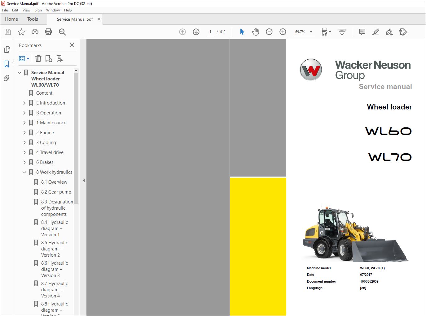
Wacker Neuson WL60 WL70 Wheel loader Service manual – PDF DOWNLOAD
Machine model WL60, WL70 (T)
Date 07/2017
Document number 1000352039
Language [en]
Use of the service manual
- The purpose of this service manual is to help maintain the constant operation readiness of the machine. This ensures the high value of the machine through careful maintenance and after-sales monitoring.
- The experiences of our factory personnel and service technicians are summarized in this service manual. Every sequence of images shows the procedure of a repair process.
- The provided text contains necessary instructions for adjustment, application of special tools, etc. Major repair procedures are described in such a way that smaller subtasks can also be performed individually following the respective procedures. The manual is appended according to further technical development of the machines and therefore is kept up-to-date to
- serve as a reference. For reasons of safety and security, always compare the specified values and capacities with the latest Operator’s Manual of the respective machine. Technical data, dimensions and weights are only given as an indication. Responsibility for errors or omissions not accepted. Deviations of images are possible
TABLE OF CONTENTS:
Wacker Neuson WL60 WL70 Wheel loader Service manual – PDF DOWNLOAD
E Introduction
E1 Notice on this service manual E-1
Use of the service manual E-2
Explanation of symbols and abbreviations E-3
Repair instructions E-4
E2 Technical data E-5
Chassis E-5
Engine 854E-E34TAWF (75 kW) – 4080 E-5
Engine 854E-E34TAWF (86 kW) – 5080 E-6
Permissible inclination E-7
Electrical system E-7
Machine-travel hydraulics E-7
Operating hydraulics E-8
Brakes E-8
Tires E-8
Steering system E-9
Electrical system E-9
Noise emissions E-9
Vibration E-9
Machine weight E-11
Payload/load-carrying capacity/axle load E-11
Dimensions, general E-11
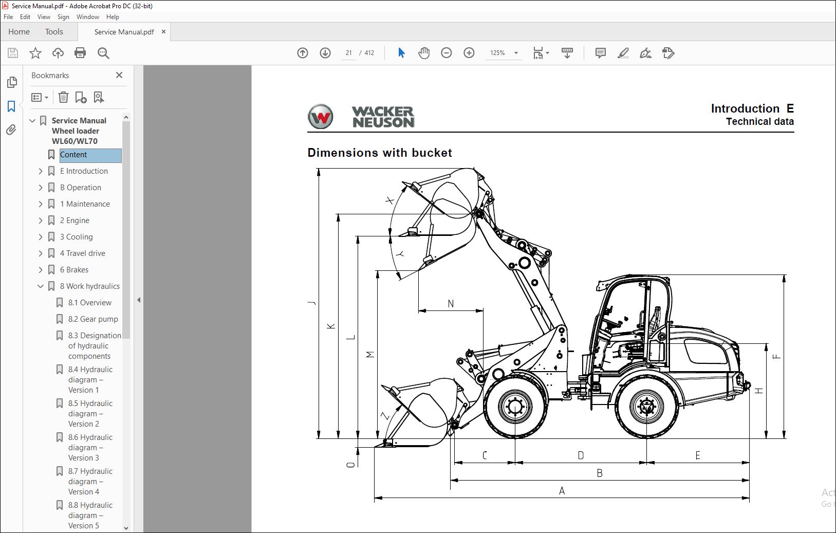
Dimensions with bucket E-13
Dimensions with pallet forks E-14
E3 Tightening torques E-15
General tightening torques E-15
Specific tightening torques E-15
Torque values for metric coarse-pitch thread E-16
Torque values for metric fine-pitch thread E-17
Tightening torques for hydraulic screw connections and climate screw fixtures with taper connections
and O-rings DIN 3865 E-18
Tightening torques for hydraulic screw connections with cutting ring DIN 3861 E-19
Tightening torques for hydraulic screw struts SDS E-20
Tightening torques for hydraulics rotating screw connections E-23
Tightening torques for hollow screws DIN 7643 E-23
Tightening torques for adjustable hydraulic screw struts SDE E-24
Tightening torques for brake line screw connections E-26
Tightening torques for worm drive hose clamps E-26
Tightening torques for spring-loaded worm drive hose clamps E-26
E4 Safety instructions E-27
Pay particular attention to the following E-27
Safety symbols and signal words E-27
Safety and Accident Prevention Regulations E-28
Safety instructions for repair work E-29
Safety instructions for work on the engine E-32
Safety instructions for work on the hydraulic system E-33
Safety instructions for work on the air conditioning system E-35
Safety instructions for work on traveling drive and axles E-35
Safety instructions for work on the braking system E-35
Safety instructions for work on the frame E-36
Safety instructions for work on the electrical system E-38
Safety instructions for work on the wheels E-38
E5 Special tools E-39
Claws and extractors E-39
Clamp E-39
I-2 SHB 4080 * 10 * EN_WL60IVZfm
I
B Operation
B1 Machine outside view B-2
B2 Overview of control elements B-4
Control and display elements B-5
Indicating instruments B-7
Multi-functional lever B-8
Overview of rotary switches B-9
Overview of switch panels B-9
B3 Indicator lights and warning lights (overview) B-13
Description of indicator lights and warning lights B-13
1 Maintenance
11 Information on maintenance 1-1
Responsibilities and prerequisites 1-1
Safety instructions 1-1
Battery master switch 1-5
12 Maintenance overview 1-6
Daily/weekly maintenance 1-6
Inspection schedules 1-7
Inspection intervals 1-10
13 Lubrication plan 1-13
Overview of lubrication points on the chassis 1-13
Overview of lubrication points on the load arm 1-15
Overview of lubrication points on the telescopic boom 1-17
14 Fluids and lubricants 1-19
Fluids and lubricants (overview) 1-19
Perkins engine 1-19
15 Cleaning and maintenance 1-20
Information on cleaning and maintenance 1-20
Information on cleaning 1-21
General safety check 1-21
16 Lubrication work 1-22
Lubrication 1-22
Lubricating with the central lubrication system (option) 1-22
Central lubrication system diagram 1-25
Installing the high-pressure hoses on the central lubrication system 1-26
Instructions for troubleshooting in case of central lubrication system blocking 1-27
Repairing a blocking distributor of the central lubrication system 1-28
Troubleshooting table for central lubrication system 1-29
17 Fuel system 1-30
Information on the fuel system 1-30
Fuel system 1-30
Refueling with diesel fuel 1-31
Maintenance fuel filter 1-32
Replacing the fuel filter element 1-34
Replacing the additional fuel filter element 1-36
Bleeding the fuel system 1-38
18 Engine lubrication system 1-39
Replace the engine oil and engine oil filter 1-39
Checking the engine oil level daily 1-39
Adding engine oil 1-39
Change the engine oil 1-40
Replacing the engine-oil filter cartridge 1-41
Reset the low oil indicator 1-42
19 Diesel engine and hydraulics cooling system 1-44
Information on the cooling system 1-44
Information on the coolant 1-44
SHB 4080 * 10 * EN_WL60IVZfm I-3
I
Information on inspection and cleaning work on the cooling system 1-45
Temperature indicator: diesel engine coolant 1-46
Cleaning the radiator fins 1-47
Draining coolant 1-48
110 Air filter 1-50
Information on the engine air filter system 1-50
Checking air filter contamination 1-51
Replacing the filter cartridge 1-52
Checking/replacing the safety engine air filter 1-53
111 V-ribbed belt 1-54
Checking -the V-ribbed belt 1-54
Re-tensioning / replacing the V-ribbed belt 1-55
Re-tensioning-the V-ribbed belt 1-55
Replacing-the V-ribbed belt 1-55
112 Hydraulic system 1-56
Information on the hydraulic system 1-56
Monitoring: hydraulic oil and the return filter warning message 1-56
Information on hydraulic oil 1-58
Check the hydraulic oil level once a day 1-58
Adding hydraulic oil 1-59
Changing the filter insert 1-60
Replace the hydraulic oil 1-61
Bleeding the hydraulic system 1-62
Important information on the use of biodegradable oil 1-63
Checking hydraulic pressure lines 1-64
Important notice on flexible lines 1-64
113 Maintenance of the electrical system 1-65
Information on the electrical system 1-65
Safety instructions regarding the electrical system and the battery 1-65
Checking/replacing the battery 1-66
Inspection and maintenance on the electrical system at regular intervals 1-67
Checking the alternator 1-67
Checking/replacing fuses 1-68
Checking/replacing the main fuse box and the switching relays 1-69
Maintenance: automatic trailer coupling 1-70
Check the trailer coupling for wear 1-70
General maintenance and cleaning work 1-71
Cleaning inside the cabin 1-72
Cleaning the diesel engine and the engine compartment 1-72
Maintenance of attachments and of the work equipment 1-73
114 Oil levels: rear axle transfer gearbox 1-74
Oil level of the front axle 1-75
Oil levels: front and rear axle planetary drives 1-76
115 Maintenance of the braking system 1-77
Important safety instructions regarding the brake system 1-77
Checking/adding brake fluid 1-77
116 Tires 1-78
Information on tires 1-78
Inflating the tires 1-79
Wheel change 1-80
Checking the liquid level of the tires 1-80
Ballasting wheels with liquid 1-81
117 Maintenance and servicing work on attachments 1-82
Information on attachments 1-82
118 Maintenance of options 1-83
Automatic trailer coupling 1-83
119 Exhaust gas treatment 1-84
I-4 SHB 4080 * 10 * EN_WL60IVZfm
I
Information on exhaust-gas treatment 1-84
Regeneration of diesel particulate filter 1-85
2 Engine
21 Engine designation 2-1
22 Requirements for the diesel fuel 2-1
23 Requirements for the coolant 2-1
24 Motor oil specifications 2-2
25 Diesel engine 854E-E34TA 2-3
Overview 2-3
Overview of engine components 854E 2-5
Description of the engine components 2-5
26 Diesel engine 854F-E34TA 2-17
Overview 2-17
Description of the engine components 854F 2-19
27 Electronic accelerator pedal 2-23
Removing and installing 2-23
28 854E engine removal and installation 2-24
Preparations 2-24
29 854F engine removal and installation 2-27
Preparations 2-27
Removing the radiator 2-28
Remove attachments and disconnect the electric connections 2-30
210 Maintenance 2-36
Overview of maintenance intervals 2-36
Valve clearance 2-38
Clean the exhaust gas recirculation (EGR) 2-38
Check / clean the charge air cooler block 2-38
Crankcase ventilation 2-40
Water pump 2-42
Engine oil 2-42
Replace the self-tensioning alternator and fan belt 2-44
211 Diesel exhaust fluid 2-46
Clean the DEF filler neck sieve 2-46
Fill the diesel exhaust fluid 2-47
Diesel exhaust fluid – Clean/replace the filter 2-49
Intake fitting of the DEF pump – Clean the sieve 2-50
Diesel exhaust gas fluid tank – see 2-51
Replace the filter of the DEF-collector line 2-53
Checking, cleaning and replacing the engine air filter element 2-54
3 Cooling
31 Cooling system overview 3-1
32 Removing/installing the radiator 3-2
Removing the radiator 3-2
4 Travel drive
41 Traveling drive hose routing 4-1
42 Manifold hose routing 4-2
43 Variable displacement pump hose routing 4-3
44 Rear hydraulic connection 4-4
45 Overview: test ports and HP valves of the drive (A4VG71DA1D8/32R) 4-5
46 Machine-travel hydraulics 4-6
Check and adjust the starting speed 4-6
47 Checking the high pressure of the variable displacement pump 4-7
48 Checking the boost pressure of the variable displacement pump 4-9
49 Overview: test ports of the variable displacement motor (A6V140HA1R1/63W) 4-11
Setting the travel speed 4-12
Checking and adjusting the control initiation of the variable displacement motor 4-13
SHB 4080 * 10 * EN_WL60IVZfm I-5
Checking the control initiation 4-13
Set control initiation 4-14
Finishing work 4-14
410 Check the driving direction identification 4-15
Solenoid switching 4-15
411 Checking and adjusting inching 4-17
Checking the inching 4-17
Adjusting the inching (front axle with drum brake) 4-18
Adjusting the inching (front axle with disc brake) 4-18
412 Test log for model 4-20
414 Troubleshooting 4-23
No forward or reverse travel 4-23
Machine travel starts too early 4-24
Machine travel starts too late 4-25
Severe engine droop 4-26
Not enough traction force 4-27
Travel speed is not reached 4-28
6 Brakes
61 Service and parking brake (drum brake) 6-1
62 Parking brake (disc brake) 6-2
Overview of the parking brake 6-3
63 Service brake (disc brake) 6-4
64 Brake pad change (drum brake) 6-1
Basic setting 6-2
65 Changing brake pads (disc brake) 6-5
Parking brake 6-5
Service brake (disc) 6-8
Replace the spring-loaded cylinder 6-14
8 Work hydraulics
81 Overview 8-1
Setup of the load arm 8-1
Setup of the telescopic boom 8-2
Setup of the pilot control 8-3
Adjusting instructions for the restrictor (optional working platform) 8-4
82 Gear pump 8-7
Overview 8-7
Checking the gear pump 8-7
Removing/installing the gear pump 8-9
83 Designation of hydraulic components 8-12
84 Hydraulic diagram – Version 1 8-15
85 Hydraulic diagram – Version 2 8-17
86 Hydraulic diagram – Version 3 8-19
87 Hydraulic diagram – Version 4 8-21
88 Hydraulic diagram – Version 5 8-23
89 Hydraulic diagram – Version 6 8-25
810 Hydraulic diagram – Version 7 8-27
811 Hydraulic diagram – Version 8 8-29
812 Hydraulic diagram – Version 9 8-31
813 Hydraulic diagram – Version 10 8-33
814 Hydraulic diagram – Version 11 8-35
815 Hydraulic diagram – Version 12 8-37
816 Hydraulic diagram – Version 13 8-39
817 Hydraulic diagram – Version 14 8-41
9 Electrical system
91 Fuses 9-1
Fuse boxes 9-1
I-6 SHB 4080 * 10 * EN_WL60IVZfm
Fuse assignment 9-1
92 Functional groups 9-5
Equipment identifiers 9-5
Electrical diagram – power supply 9-11
Voltage supply ECU TTC77; Lighting of joystick 9-12
Perkins 854 E engine 9-13
93 Indicating instruments 9-16
94 Travel functions 9-17
95 Lights 9-18
96 Turn indicator system, horn 9-20
97 Window wiper and wash system 9-21
98 Working light, rotating beacon 9-22
99 3rd control circuit electric connections 9-23
910 Hydraulic system 9-24
911 Air conditioning system, operator seat 9-27
912 Interior (radio, lighting, safe load indicator) 9-28
913 Functional groups 9-29
Equipment identifiers 9-29
Electrical diagram – voltage supply 9-39
Voltage supply ECU TTC77; Lighting of joystick 9-40
Power supply 9-41
Perkins 854 F T4F engine 9-42
914 Indicating instruments 9-51
915 Travel functions 9-52
916 Lights 9-54
917 Turn indicator system, horn 9-57
918 Window wiper and wash system 9-58
919 Working light, rotating beacon 9-60
920 Hydraulic control circuits, electric connections 9-61
921 Hydraulic system 9-67
922 Hydraulics 2 9-70
923 14-pole power outlet 9-72
924 Radio, cigarette lighter, interior lighting 9-76
925 Central lubrication system 9-77
12 Malfunctions
121 Towing a machine 12-1
Preparations for towing 12-1
Towing the vehicle 12-2
After towing 12-2
122 Error code lists 12-3
Engine control unit Perkins 854E
VIDEO PREVIEW OF THE MANUAL:
PLEASE NOTE:
- This is not a physical manual but a digital manual – meaning no physical copy will be couriered to you. The manual can be yours in the next 2 mins as once you make the payment, you will be directed to the download page IMMEDIATELY.
- This is the same manual used by the dealers inorder to diagnose your vehicle of its faults.
- Require some other service manual or have any queries: please WRITE to us at [email protected]
S.M


