Wacker Neuson WL28 Wheel loader Operating Manual – PDF DOWNLOAD
IMAGES PREVIEW OF THE MANUAL:
DESCRIPTION:
Wacker Neuson WL28 Wheel loader Operating Manual – PDF DOWNLOAD
Preface
This operator’s manual describes how to operate and service the loader. They provides operating and maintenance personnel with the necessary knowledge of the loader’s functional characteristics in order to allow them to handle, properly service/inspect, clean and look after the loader safely and without danger, and to ensure that the technical safety regulations for the loader are complied with
Observing the requirements in this operator’s manual ensures:
• proper, safe and professional operation of the loader
• professional maintenance, cleaning and care for the
loader
• compliance with the necessary technical safety regulations
If required, the user/operator of the loader should supplement the operator’s manual with instructions and regulations regarding environmental protection and national health and safety regulations relating to accident prevention
NOTE
This operator’s manual must always be kept either on the loader or at the point of use.
The operator’s manual must be read and applied by all persons involved in work with or on the loader, for example with regard to:
• Operation including setup, remedying faults during operation, care, disposal of auxiliary materials and operating
materials (lubricants, fluids and oils) as well as disposal of the entire loader
• Servicing (inspection, maintenance, care)
• Transport
NOTE
This operator’s manual does not contain instructions on how to carry out extensive servicing or repairs. This type of work must only be performed by qualified specialists
Basic information
- In Germany, the following rules must be followed when driving on public roads: Loaders with a maximum speed of up to 20 km/h require no approval. They do however require an operating license, which is issued by the motor vehicles registration office.
- In addition, the name (first name and surname) and the place of residence or the company name and the location of the company’s registered office must be clearly displayed on the left-hand side of the loader in non-smudging lettering (§64b of the German Road Traffic Licensing Regulations, StZVO).
- The operator is responsible for ensuring that appropriate insurance cover is in place. The operator must check with his insurance provider whether or not the loader is covered under the terms of his public liability insurance, or whether he needs to take out separate third party insurance for this purpose. Every new user must be instructed before using the loader for the first time.
Notes on using the operator’s manual:
• Read the operator’s manual carefully before using the
loader.
• Observe all safety instructions.
• Follow the regulations and laws which are applicable in
the place of use.
• Follow the regulations of the federal association of statutory
accident insurances (VGB).
• Always keep the operator’s manual in a clean and orderly
state together with the loader.
- Symbols will he used to highlight any hazards to persons or material which cannot be ruled out during the course of normal work which is carried out in accordance with the proper use of the loader. Descriptions relate to the direction of travel of the loader, so directional information should always be interpreted looking in the direction of travel
- 1.1 Notes about this operator’s manual
- All of the information about technical data in this operator’s manual relates to series models which have been tested under standard operating conditions for Central Europe; all such data relates to the standard functions of these series models. The equipment and its functional modalities and accessories depend on the relevant model and the product options, as well as on the national requirements which apply specifically in the country of sale.
- Illustrations may show products which are not mentioned in the text or which are not supplied as standard. The descriptions, illustrations, weight information and technical data are not binding and correspond to the state of the art at the time of printing. We must reserve the right to make changes without prior notice in the areas of design, equipment, appearance and technology on account of the ongoing further development of the products. Please get in touch with us if you require any special functions which can only be made available with the aid of additional components and/or which require special framework conditions.
- We will be happy to answer your questions and let you know whether and under which conditions for the product and its surroundings special functions can be implemented. If you have concerns about the load capacity or mode of operation of our products because of special circumstances, we recommend carrying out test work under controlled framework conditions. Please make sure that you always follow without fail all safety instructions in this operator’s manual and the statutory and regulations of the federal association of statutory accident insurances at the point of use.
- Despite taking the greatest care, we cannot rule out the possibility of deviations from drawings or dimensions, calculation errors, printing errors or incompleteness in this operator’s manual. As a result, we accept no liability for the correctness and completeness of the information we have provided in this operator’s manual.
- We guarantee that our products will work properly and without problems within the framework of our General Terms and Conditions of Business. As a matter of principle we do not offer more far-reaching guarantees. We do not accept liability beyond the scope of our liability as defined in our General Terms and Conditions of Business.
TABLE OF CONTENTS:
Wacker Neuson WL28 Wheel loader Operating Manual – PDF DOWNLOAD
Preface 11
1 Basic information 12
11 Notes about this operator’s manual 13
12 Explanation of the symbols used in this operator’s manual 14
13 Warranty and liability 15
14 Proper use 18
2 Basic safety instructions 20
21 Organisational measures 21
22 Selection and qualification of personnel / basic duties 23
23 Safety instructions for certain operating phases 24
231 Safety instructions for normal operation 24
232 Safety instructions for other operating modes 26
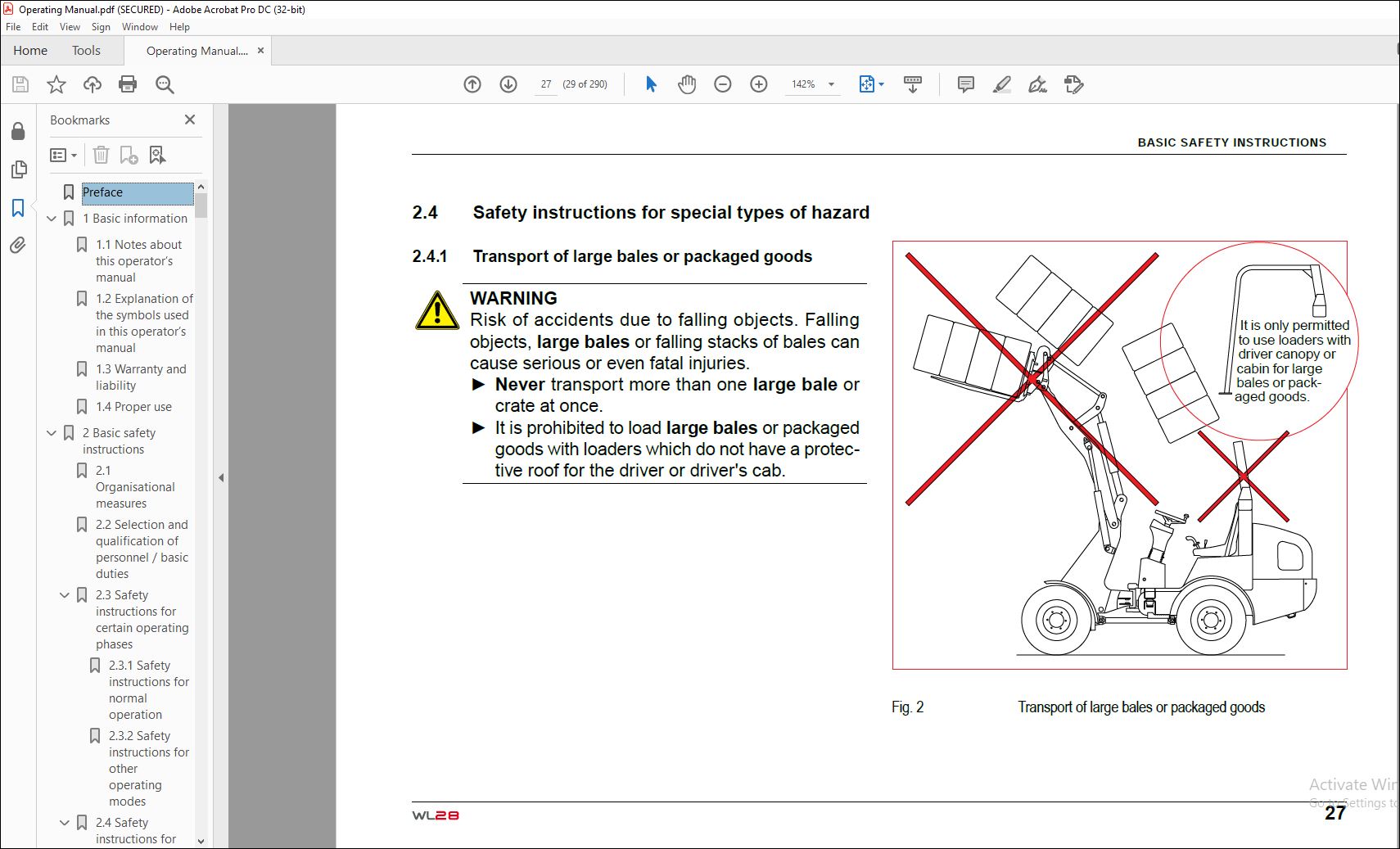
24 Safety instructions for special types of hazard 29
241 Transport of large bales or packaged goods 29
242 Working in the vicinity of overhead power lines 30
243 Electrical power 31
244 Fire hazard 31
245 Gas, dust, vapor, smoke 32
246 Hydraulic systems, pneumatic systems 32
247 What to do if the loader tips over 33
248 Noise 33
249 Oil, grease and other chemical substances 33
25 Transporting and towing/restarting 34
26 Final decommissioning/dismantling 34
27 Safety stickers used 35
28 Safety devices 39
281 Fire extinguisher 39
282 Rotating beacon 39
283 Lowering brake valves on lifting and tipping cylinders 40
284 Battery disconnect switch 41
285 Safety belt 42
286 Seat contact switch 42
287 Emergency exit 43
288 Audible reverse warning device 43
289 Locking mechanism for the lift frame 44
3 Technical data 45
31 Technical description 45
32 Loader data 47
33 Dimensions 52
331 Dimensions (Loaders with driver’s canopy) 52
332 Dimensions (Loaders with cab) 54
34 Factory signs 56
4 Description of the indicator, warning and control elements 58
41 Operating elements and instruments 58
42 Control and warning lights 60
43 Switches / toggle switches 64
44 Indicator devices 68
5 Operating and operation 70
51 Before starting up 70
511 Fueling 70
512 Getting in 72
516 Doors and windows 75
513 Adjusting the steering column 77
514 Adjusting the driver‘s seat 78
515 Seat belt 80
52 Starting up 83
521 Lighting system and signal horn 84
522 Headlights 85
525 Rotating beacon 87
526 Wipers and windscreen washer system 88
527 Ventilation and heating of the cab 89
523 Before starting the engine 91
524 Starting the engine 91
53 Driving 96
531 Parking brake 96
532 Preparation for driving in public traffic 97
533 Description of the drive hydraulics 98
534 Driving 99
535 Stopping and parking103
54 Work operation104
541 Control lever for the lift frame106
542 Locking mechanism for the lift frame108
543 Operating lever for additional hydraulics110
544 Differential lock114
545 Changing attachments116
546 Bucket127
547 Manure fork133
548 Pallet fork135
549 Measures in the event of the loader tipping over140
5410 Precaution measures for various weather conditions141
55 Additional equipment143
56 Optional equipment – collapsible driver’s canopy152
561 Folding down the collapsible driver’s canopy155
562 Bringing the collapsible driver’s canopy into the protection ON position159
6 Towing and transporting160
61 Towing160
62 Transporting163
7 Measures in the event of power loss171
8 Discharging residual pressure in the hydraulic system172
9 Securing the loader175
10 Servicing and inspection176
101 Basic safety instructions for servicing and inspection176
102 Servicing and inspection intervals182
103 Lubrication schedule194
104 Cleaning the loader196
105 General safety check198
106 Specifications and filling quantities198
107 Servicing and inspection work200
1071 Preparation for maintenance and inspection work201
1072 Servicing the engine206
1073 Servicing the fuel system212
1074 Servicing the air filter system217
1075 Servicing the cooling system220
1076 Servicing the hydraulic system228
1077 Servicing the axles237
1078 Servicing the brakes241
1079 Maintaining the collapsible driver’s canopy244
10710 Servicing the tires and wheels246
10712 Servicing the cab vent filter250
10713 Filling the container for the windscreen washer system251
10711 Servicing the electrical system252
108 Jump-starting / emergency starting260
109 Shutting down and restarting the loader262
11 Troubleshooting and emergency maintenance264
12 Safety instructions for repairs268
121 General safety regulations for repairs268
122 Engine271
123 Welding work271
124 Hydraulic system273
125 Brakes273
13 Final shutdown of the loader / decommissioning274
14 Appendix276
Ordering replacement parts276
Index 278
List of figures284
A279
Adding hydraulic fluid232
Adjusting the driver‘s seat 78
Adjusting the driver‘s seat 78
Adjusting the fork arm spacing136
Adjusting the seat belt 81
Adjusting the steering column 77
Air filter dust valve218
Air pressure table for tires247
At high outside temperatures141
At low outside temperatures141
B279
Battery 256
Blocking the articulated joint164
Braking and stopping102
C279
Changeover valve applies tilting in/out function to additional hydraulics145
Changing attachments116
Changing the axle oil239
Changing the coolant226
Changing the drive direction103
Changing the engine oil208
Changing the engine oil filter210
Changing the fuel pre-filter214
Changing the hydraulic fluid232
Changing the main fuel filter215
Changing the return filter element234
Changing wheels248
Checking / changing the safety filter219
Checking the antifreeze mix225
Checking the axle oil level237
Checking the brake fluid level / topping up brake fluid242
Checking the coolant level / refilling the coolant224
Checking the engine oil level206
Checking the hydraulic fluid level230
Checking V-belt tension / Tensioning the V-belt222
Check main air filter element / clean / replace218
Cleaning the cooling system227
Control lever for the lift frame106
Coupling and uncoupling the connections for additional hydraulics122
Coupling attachments119
Coupling with hydraulic quick-change system120
Coupling with mechanical quick-change system123
D279
Daily servicing182
Depressurized return line147
Description of the indicator, warning and control elements 58
Description of the starting process 93
Detent mechanism for the control lever for the additional hydraulics113
Dimensions 52
Disconnecting and connecting the battery / changing the battery258
Doors and windows 75
Drive direction switch 99
Driving off with the loader102
E279
Each time before starting work105
EC Declaration of conformity 17
Electrical outlet on the lift frame148
F279
Fastening the seat belt 80
Filling the container for the windscreen washer system251
Foldable rollover bar143
Fueling 70
Fuse allocation252
G279
Getting in 74
H279
Headlights 85
Hydraulic fluid cooler229
Hydraulic locking mechanism for attachments112
Hydro connection additionally via additional control device147
Hydro connection additionally via changeover valve146
I279
Idle speed adjustment for cold starting 94
If the engine does not start 95
Independent driving onto the transport device165
Inflating the tires246
Inspection after 30 operating hours (First inspection)184
Inspection after 500 operating hours186
Inspection intervals189
J279
Jump-starting / emergency starting260
L279
Lashing the loader168
Lengthening the seat belt 82
Level indicator129
Lighting system and signal horn 84
Loader data 47
Loading with crane166
Lubrication schedule194
M279
Measures in the event of the loader tipping over140
Moving the loader onto a transport vehicle163
O279
Opening the lowering brake valves174
Operating lever for additional hydraulics110
Optional multi-function lever for multiple functions150
Ordering replacement parts276
R279
Releasing the seat belt 80
S278
Safety information for collapsible driver’s canopy152
Seat belt 80
Servicing the air filter system217
Servicing the axles237
Servicing the battery257
Servicing the brakes241
Servicing the cab vent filter250
Servicing the cooling system220
Servicing the electrical system252
Servicing the engine206
Servicing the fuel system212
Servicing the hydraulic system228
Servicing the tires and wheels246
Servicing the water separator213
Short-circuiting the drive161
Shortening the seat belt 82
Specifications and filling quantities198
Starting the engine 91
Switching gears101
T278
Technical description of the loader 45
Tilting the driver‘s platform202
Topping up engine oil208
Towing equipment161
Troubleshooting and emergency maintenance264
Troubleshooting on the driving pump / oil motor266
Troubleshooting on the loader267
U278
Uncoupling attachments124
Uncoupling with hydraulic quick-change system124
Uncoupling with mechanical quick-change system126
V278
Ventilation and heating of the cab 89
Ventilation filter / hydraulic fluid filler neck230
Venting the fuel system216
Venting the hydraulic system236
Vibrations (weighted effective value) 50
W278
Weekly servicing183
Wipers and windscreen washer system 88
Working with the bucket130
Working with the pallet fork138
Fig 1 Document pocket 16
Fig 2 Transport of large bales or packaged goods 29
Fig 3 Safety stickers 35
Fig 4 Fire extinguisher 39
Fig 5 Attaching the rotating beacon 39
Fig 6 Lowering brake valve 40
Fig 7 Battery disconnect switch 41
Fig 8 Safety belt 42
Fig 9 Emergency exit 43
Fig 10 Lever for locking the lift frame 44
Fig 11 Dimensions (Loaders with driver’s canopy) 52
Fig 12 Dimensions (Loaders with cab) 54
Fig 13 Vehicle ID no 56
Fig 14 Operating elements 58
Fig 15 Control and warning lights 60
Fig 16 Switches / toggle switches 64
Fig 17 Indicator devices 68
Fig 18 Fuel filler neck 71
Fig 19 Getting in 74
Fig 20 Locking the restraining bar 74
Fig 21 Cab door locking mechanism 75
Fig 22 Cab door locking 76
Fig 23 Releasing locked cab doors 76
Fig 24 Adjusting the steering column 77
Fig 25 Adjusting the driver‘s seat 79
Fig 26 Fastening the seat belt 81
Fig 27 Adjusting the seat belt 82
Fig 28 Lighting / signal horn 84
Fig 29 Switch for work lights (Loaders with driver‘s canopy) 85
Fig 30 Switch for work lights (Loaders with cab) 86
Fig 31 Switch for rotating beacon 87
Fig 32 Switches for windscreen wipers 88
Fig 33 Heating controller 89
Fig 34 Ventilation jets 90
Fig 35 Ignition key 93
Fig 36 Idle speed adjustment 94
Fig 37 Operating lever for parking brake 97
Fig 38 Changing direction101
Fig 39 Control lever for the lift frame107
Fig 40 Lever for locking the lift frame109
Fig 41 Operating lever for additional hydraulics111
Fig 42 Hydraulic connections111
Fig 43 Releasing the hydraulic locking mechanism for attachments112
Fig 44 Switch for differential lock115
Fig 45 Coupling – hydraulic locking mechanism120
Fig 46 Connecting the additional hydraulics121
Fig 47 Coupling – mechanical locking mechanism123
Fig 48 Locking of the mechanical locking mechanism123
Fig 49 Uncoupling – hydraulic locking mechanism125
Fig 50 Uncoupling mechanical locking mechanism126
Fig 51 Control lever movements128
Fig 52 Level indicator129
Fig 53 Loading work 1130
Fig 54 Loading work 2131
Fig 55 Loading work 3131
Fig 56 Excavation work 4132
Fig 57 Excavation work 5132
Fig 58 Correct fork arm spacing136
Fig 59 Adjusting the fork arm spacing137
Fig 60 Foldable rollover bar144
Fig 61 Switch for changeover valve145
Fig 62 Additional hydraulic connections146
Fig 63 Additional control lever147
Fig 64 Depressurized return line147
Fig 65 Electrical outlet on the lift frame148
Fig 66 Switch for the electrical outlet on the lift frame (1)148
Fig 67 Switch for the electrical outlet on the lift frame (2)149
Fig 68 Optional multi-function lever150
Fig 69 Transporting large bales or packaged goods (collapsible driver’s canopy)152
Fig 70 Dimensions (collapsible driver’s canopy)153
Fig 71 Components (collapsible driver’s canopy)154
Fig 72 Preparations for folding down the driver’s canopy (collapsible driver’s canopy)155
Fig 73 Releasing the securing pins (collapsible driver’s canopy)155
Fig 74 Folding down the front pillars forwards (collapsible driver’s canopy)156
Fig 75 Fold in the roof sections (collapsible driver’s canopy)157
Fig 76 Folding down the rear pillar (collapsible driver’s canopy)158
Fig 77 Inserting the front securing pins (collapsible driver’s canopy)159
Fig 78 Towing equipment161
Fig 79 Short-circuiting the drive162
Fig 80 Buckling guard164
Fig 81 Independent driving onto the transport device165
Fig 82 Attachment point stickers166
Fig 83 Attachment points167
Fig 84 Loading with crane167
Fig 85 Lashing point stickers168
Fig 86 Lashing points169
Fig 87 Lashing the loader170
Fig 88 Reducing residual pressure173
Fig 89 Opening the lowering brake valves174
Fig 90 Points of lubrication194
Fig 91 Handle for the engine bonnet201
Fig 92 Cab tilt lever203
Fig 93 Position of the driver‘s platform mounting screws204
Fig 94 Driver‘s platform mounting screw, front205
Fig 95 Driver‘s platform mounting screw, rear205
Fig 96 Driver‘s platform safety support205
Fig 97 Engine oil dipstick206
Fig 98 Checking the engine oil / filling the oil207
Fig 99 Engine oil drain opening209
Fig 100 Location of the engine oil filter211
Fig 101 Engine oil filter211
Fig 102 Water separator213
Fig 103 Fuel pre-filter, main fuel filter214
Fig 104 Changing the main fuel filter215
Fig 105 Venting the fuel system216
Fig 106 Location of the air filter218
Fig 107 Air filter elements218
Fig 108 Radiator221
Fig 109 Checking the V-belt tension223
Fig 110 V-belt223
Fig 111 Tensioning the V-belt223
Fig 112 Radiator opening225
Fig 113 Checking the antifreeze mix225
Fig 114 Cleaning the cooling system227
Fig 115 Hydraulic fluid cooler229
Fig 116 Ventilation filter231
Fig 117 Hydraulic fluid dip stick231
Fig 118 Hydraulic fluid drain plug233
Fig 119 Return filter235
Fig 120 Filter insert235
Fig 121 Differential237
Fig 122 Transfer case238
Fig 123 Wheel reduction238
Fig 124 Brake fluid container243
Fig 125 Greasing the front securing pins (collapsible driver’s canopy)245
Fig 126 Cab vent filter250
Fig 127 Location of the windscreen washer container251
Fig 128 Fuses253
Fig 129 Fuse box254
Fig 130 Location of the battery256
Fig 131 Servicing the battery257
Fig 132 Removing the battery258
Fig 133 Connecting the jumper cables260
VIDEO PREVIEW OF THE MANUAL:
PLEASE NOTE:
- This is the SAME MANUAL used by the dealerships to diagnose your vehicle
- No waiting for couriers / posts as this is a PDF manual and you can download it within 2 minutes time once you make the payment.
- Your payment is all safe and the delivery of the manual is INSTANT – You will be taken to the DOWNLOAD PAGE.
- So have no hesitations whatsoever and write to us about any queries you may have : heydownloadss @gmail.com
S.M