

Wacker Neuson Group WL20e Wheel loader Service Manual – PDF DOWNLOAD
IMAGES PREVIEW OF THE MANUAL:
DESCRIPTION:
Wacker Neuson Group WL20e Wheel loader Service Manual – PDF DOWNLOAD
Use of the service manual
- The purpose of this service manual is to help maintain the constant operation readiness of the machine. This ensures the high value of the machine through careful maintenance and after-sales monitoring. The experiences of our factory personnel and service technicians are summarized in this service manual.
- Every sequence of images shows the procedure of a repair process. The provided text contains necessary instructions for adjustment, application of special tools, etc. Major repair procedures are described in such a way that smaller subtasks can also be performed individually following the respective procedures. The manual is appended according to further technical
- development of the machines and therefore is kept up-to-date to serve as a reference. For reasons of safety and security, always compare the specified values and capacities with the latest Operator’s Manual of the respective machine. Technical data, dimensions and weights are only given as an indication. Responsibility for errors or omissions not accepted. Deviations of images are possible.
Information
Careful and prudent working is the best way to avoid accidents
TABLE OF CONTENTS:
Wacker Neuson Group WL20e Wheel loader Service Manual – PDF DOWNLOAD
E Introduction
E1 Notice on this service manual E-1
Use of the service manual E-2
Explanation of symbols and abbreviations E-3
Repair instructions E-4
E2 Technical data E-5
Permissible inclination E-5
Drive E-5
Axles E-6
Machine-travel hydraulics E-6
Operating hydraulics E-6
Brakes E-7
Tires E-7
Steering system E-8
Electrical system E-8
Noise emissions E-10
Vibration E-11
Weights E-11
Payload / bearing load / axle load E-11
Dimensions E-12
E3 Tightening torques E-14
General tightening torques E-14
Specific tightening torques E-14
Torque values for metric coarse-pitch thread E-15
Torque values for metric fine-pitch thread E-16
Tightening torques for hydraulic screw connections and climate screw fixtures with taper
connections and O-rings DIN 3865 E-17
Tightening torques for hydraulic screw connections with cutting ring DIN 3861 E-18
Tightening torques for hydraulic screw struts SDS E-19
Tightening torques for hydraulics rotating screw connections E-22
Tightening torques for hollow screws DIN 7643 E-22
Tightening torques for adjustable hydraulic screw struts SDE E-23
Tightening torques for brake line screw connections E-25
Tightening torques for worm drive hose clamps E-25
Tightening torques for spring-loaded worm drive hose clamps E-25
E4 Safety instructions E-26
Pay particular attention to the following E-26
Safety symbols and signal words E-26
Safety and accident prevention regulations E-27
Safety instructions for repair work E-28
Safety instructions for work on the engine E-30
Safety instructions for working on the hydraulic system E-31
Safety instructions for work on traveling drive and axles E-33
Safety instructions for work on the braking system E-33
Safety instructions for working on the frame and mast E-33
Safety instructions for work on the electrical system E-35
Safety instructions for work on the wheels E-35
E5 Special tools E-36
B1 Overview of control elements B-1
Description of control elements B-2
Control and display elements B-2
Display instrument B-3
Loader unit control lever B-4
Overview of switches B-5
1 Maintenance
11 Information on maintenance 1-1
Responsibilities and prerequisites 1-2
Safety instructions 1-2
Information on handling flammable liquids 1-3
Information on handling oils and greases 1-3
Information on residual pressure in the hydraulic system 1-3
Information on screw connections, pipes, hydraulic hoses 1-3
Information on batteries 1-4
Information on the electrical system 1-4
After maintenance 1-4
12 Maintenance overview 1-5
Daily/weekly maintenance 1-5
Operating hours and inspection display 1-6
Inspection schedules 1-7
Inspection intervals 1-9
Lubrication schedule 1-11
13 Fluids and lubricants 1-13
Fluids and lubricants (overview) 1-13
14 Maintenance accesses 1-14
Maintenance openings 1-14
15 Cleaning and maintenance 1-17
Information on cleaning and maintenance 1-17
Information on cleaning 1-17
General safety check 1-18
16 Lubrication work 1-19
Preparing lubrication 1-19
17 Hydraulic system 1-20
Information on the hydraulic system 1-20
Information on hydraulic oil 1-20
Change the breather filter 1-21
Checking the hydraulic oil level 1-22
Adding hydraulic oil 1-22
Changing hydraulic oil 1-23
Replacing the hydraulic oil filter insert 1-24
Bleeding the hydraulic system 1-25
18 Electrical system 1-26
Information on the electrical system 1-26
19 Exide battery 1-28
General information about batteries 1-28
Checking the battery acid level 1-29
Adding demineralized water 1-31
Top off demineralized water with an electric pump (optional) 1-32
Flow display for demineralized water (optional) 1-32
Check the fluid level in the battery container 1-33
Checking the battery acid density 1-34
Measure cell voltages 1-35
SHB WL20e * 30 I-3
Contents I
110 AGM battery 1-36
General information about batteries 1-36
Operator’s manual of the AGM battery 1-36
Disconnect / connect battery connector 1-37
Removing the battery 1-37
Measure the battery voltage and cell temperatures 1-38
Replace the battery cells 1-39
Maintaining the battery charger 1-41
Replacing the battery charger 1-41
111 Axles/traveling drive 1-44
Checking the axle oil level 1-44
Change the axle oil 1-44
Check the oil level in the distributor gearbox 1-45
Change the gear oil in the distributor gearbox 1-45
Performing maintenance on the traveling drive 1-46
112 Brake system 1-47
Overview 1-47
Information on the braking system 1-48
113 Service brake 1-49
Overview 1-49
Drum brake setup 1-50
Replace brake shoes 1-51
114 Parking brake 1-54
Check the air gap of the brake 1-54
115 Tires 1-55
Information on tires 1-55
Inflating the tires 1-56
Wheel change 1-57
Checking the liquid level of the tires 1-58
Ballasting wheels with liquid 1-58
116 Maintenance and servicing work on attachments 1-59
Information on attachments 1-59
117 Maintenance of options 1-60
Maintenance of folding protective roof for operator 1-60
118 Electrical control procedures according to DIN VDE 0701 / 0702 1-61
Protective earth resistance measurement 1-61
Insulation resistance measurement 1-64
Troubleshooting the insulation resistance measurement 1-70
2 Engine
21 Hydraulic motor M030 2-1
Overview 2-2
Removing/installing the hydraulic motor 2-3
22 Accelerator pedal B054 2-8
Overview 2-8
Removing/installing the accelerator pedal 2-9
3 Traveling drive
31 Cardan shaft 3-1
Removing/installing the cardan shaft 3-2
32 Transfer gearbox 3-4
Removing/installing the transfer gearbox 3-4
4 Axles
41 Front axle 4-1
Removing/installing the front axle 4-2
42 Rear axle 4-6
Removing/installing the rear axle 4-6
I-4 SHB WL20e * 30
I Contents
5 Brakes
51 Brake pedal 5-1
Removing/installing the brake pedal 5-2
52 Master brake cylinder 5-4
Overview 5-4
Removing/installing the master brake cylinder 5-5
53 Parking brake 5-8
Overview 5-8
Removing/installing the spring force brake 5-9
6 Steering system
61 Steering orbitrol S3 6-1
Overview 6-2
Removing/installing the steering orbitrol 6-4
62 Steering column gas spring 6-6
Removing/installing the steering column gas spring 6-6
63 Steering column 6-11
Removing/installing the steering column 6-11
64 Steering cylinder A16 6-14
Removing/installing the steering cylinder 6-14
65 Center joint 6-18
Disconnect / connect the center joint 6-18
66 Bearings in the pendulum bearing 6-23
Removing/installing bearings in the pendulum bearings 6-23
67 Lower bearing 6-25
Removing/installing lower bearing 6-25
7 Hydraulic system
71 Control valve 7-1
Overview 7-2
Removing/installing the control valve 7-9
72 Gear pump motor M031 7-12
Overview 7-12
Removing/installing the gear pump motor 7-13
73 Gear pump P51 7-17
Overview 7-17
Removing/installing the gear pump 7-18
74 Lock cylinder A4 7-20
Removing/installing lock cylinder A4 7-20
75 Lock pins 7-23
Removing/installing lock pins 7-23
76 Mast 7-24
Removing/installing the mast 7-24
77 Lifting cylinder A11, A36, A37 7-28
Removing/installing the lift cylinder 7-28
78 Tilt cylinder A45, A46, A47, A48 7-31
Removing/installing the tilt cylinder 7-31
79 Reversing lever 7-34
Removing/installing the reversing lever 7-34
710 Bearings on the pull rod 7-36
Removing/installing bearings on the pull rod 7-36
711 Hydraulic cylinder pivot bearing 7-38
Removing/installing the hydraulic cylinder pivot bearing 7-38
712 Hydraulic cylinder bearing bush 7-40
Removing/installing the hydraulic cylinder bearing bush 7-40
713 Hydraulic lines 7-42
Removing/installing the hydraulic lines 7-42
SHB WL20e * 30 I-5
Contents I
714 Designation of hydraulic components 7-44
Component list 7-44
715 Hydraulics Diagram – Vehicle without options 7-45
716 Hydraulics Diagram – Vehicle with optional lock cylinder 7-46
717 Hydraulics Diagram – Vehicle with optional 3rd control circuit Comfort 7-47
718 Hydraulics Diagram – Vehicle with optional Return without pressure 7-48
719 Hydraulics Diagram – Vehicle with optional Floating position 7-49
720 Hydraulics Diagram – Vehicle with optional hydraulic cylinder with counterbalance valve 7-50
721 Hydraulics Diagram – Vehicle with 3rd control circuit and all possible options 7-51
722 Hydraulics Diagram – Vehicle with rear hydraulic connection 7-52
723 Hydraulics Diagram – Vehicle with 4th control circuit and all options 7-53
724 Hydraulics Diagram – Steering system 7-54
725 Hydraulics Diagram – Lift cylinder 7-55
726 Hydraulics Diagram – Tilt cylinder 7-56
727 Hydraulics Diagram – EPS Plus 7-57
728 Hydraulics diagram – Differential lock 7-58
8 Electrical system
81 Overview 8-1
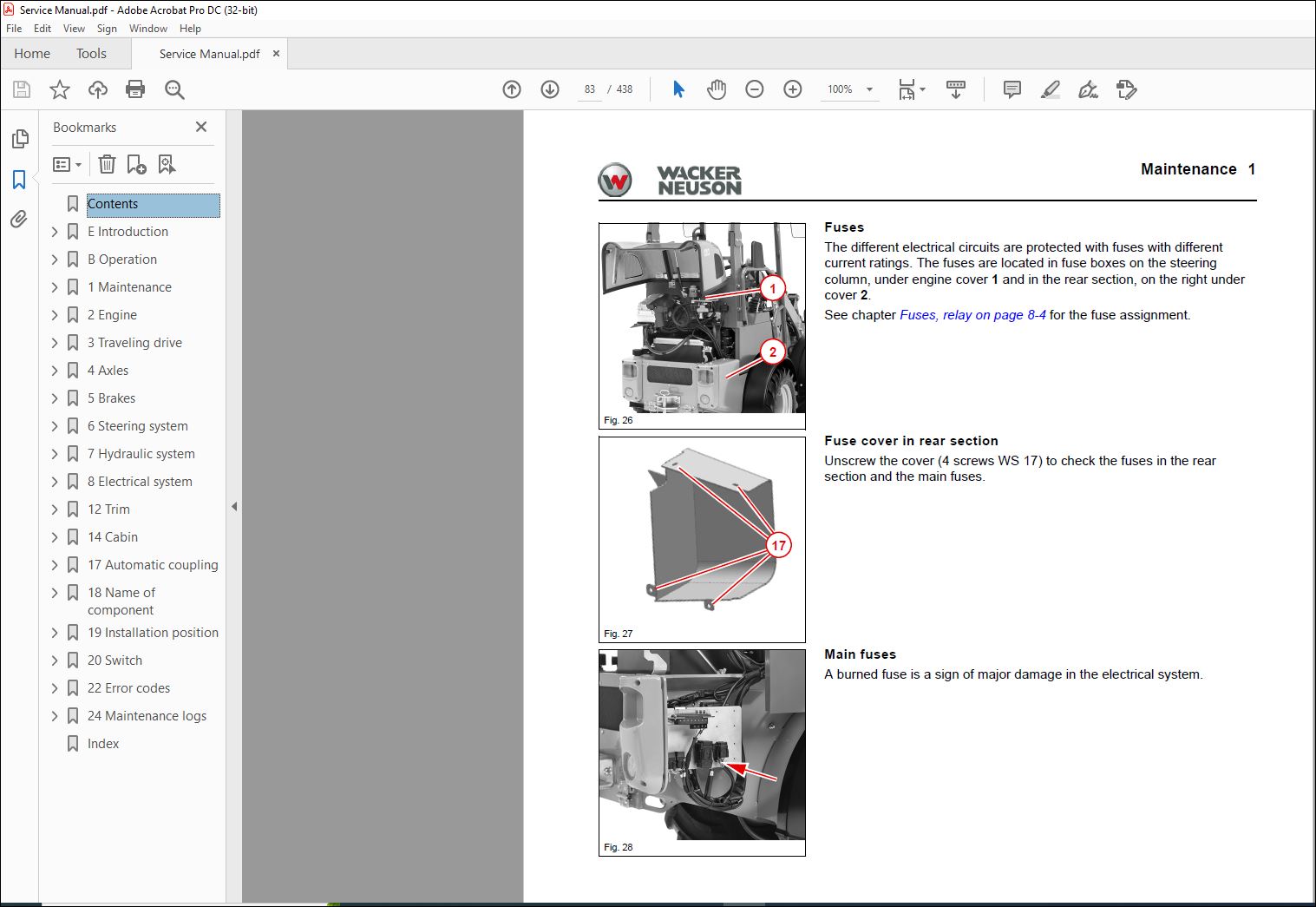
82 Fuses, relay 8-4
Fuse assignment 8-4
Relays 8-6
83 Joystick 8-7
Overview of joystick without touch buttons 8-7
Overview of the joystick with 2 touch buttons 8-8
Overview of the joystick with 4 touch buttons 8-9
Removing/installing the joystick 8-10
84 Indicating instrument P011 8-15
Removing/installing the indicating instrument 8-15
85 Main contactor K117 8-18
Overview 8-18
Removing/installing the main contactor 8-20
86 Secondary contactor K131 8-23
Overview 8-23
Removing/installing the secondary contactor 8-24
87 Twin inverter N030 8-27
Overview 8-27
Removing/installing the twin inverter 8-28
88 Voltage converter G003, G004, G005 8-31
Overview 8-31
Removing/installing the voltage converter 8-32
89 Control unit ECU N014 8-34
Overview 8-34
Removing/installing the ECU 8-35
810 Headlight with blinker 8-37
Removing/installing the headlight with blinker 8-37
811 Tail light with blinker 8-39
Removing/installing the tail light with blinker 8-39
812 Work light E007/E009/E010 8-41
Removing/installing the headlight with blinker 8-41
813 Hydraulic oil temperature sensor B007 8-42
Overview 8-42
Removing/installing the hydraulic oil temperature sensor 8-43
814 Reverse warning system B018 8-45
Overview 8-45
Removing/installing the reverse warning system 8-46
I-6 SHB WL20e * 30
I Contents
815 Switching relay for additional function K045, K046 8-47
Overview 8-47
Removing/installing the additional function switching relay 8-48
816 Electrical diagram – Supply voltage and charging switching for vehicles with Exide battery
(version 00) 8-51
817 Electrical diagram – Supply voltage and charging switching for vehicles with Exide battery
(version 01) 8-52
818 Electrical diagram – Supply voltage and charging switching for vehicles with AGM battery 8-53
819 Electrical diagram – Driving function for vehicles with an Exide battery 8-54
820 Electrical diagram – Driving function for vehicles with an AGM battery 8-55
821 Electrical diagram – Gear pump drive for vehicles with an Exide battery 8-56
822 Electrical diagram – Gear pump drive for vehicles with an AGM battery 8-57
823 Electrical diagram – Indicating instrument, diagnostic interface 8-58
824 Electrical diagram – Work light, rotating beacon, horn – version without steering column switch 8-59
825 Electrical diagram – Work light, rotating beacon, horn – version with steering column switch 8-60
826 Electrical diagram – Comfort seat, work light, EPS – version without steering column switch 8-61
827 Electrical diagram – Comfort seat, work light, EPS – version with steering column switch 8-62
828 Electrical diagram – Tool lock 8-63
829 Electrical diagram – Electric function, comfort 3rd control circuit – Version 1 8-64
830 Electrical diagram – Electric function, comfort 3rd control circuit – Version 2 8-65
831 Electrical diagram – EPS Plus 8-66
832 Electrical diagram – StVZO lighting for vehicles with an Exide battery 8-67
833 Electrical diagram – StVZO lighting for vehicles with an AGM battery 8-68
834 Electrical diagram – Hazard warning system 8-69
835 Pin assignment 8-70
B003 – Warning system plug 8-70
B007 – Hydraulic oil temperature sensor plug 8-70
B043 – Plug of the position sensor, gate I 3rd control circuit 8-70
B044 – Plug of the position sensor, gate II, rolling in/rolling out 8-70
B045 – Plug of the position sensor, gate III, raise/lower 8-70
B046 – Plug of position sensor gate IV 8-71
B054 – Drive pedal plug 8-71
B083 – Plug of speed sensor for driving engine 8-71
B084 – Plug of temperature sensor for driving engine 8-71
B085 – Plug of speed sensor for working engine 8-72
B086 – Plug of temperature sensor for working engine 8-72
B103 – Current sensor plug 8-72
E009 – Front work light plug 8-72
E010 – Front work light plug 8-72
F021 – Fuse 5 A 8-73
F023 – Fuse 5 A 8-73
F025 – Fuse 5 A 8-73
F303 – Fuse 12 V terminal 30 8-73
F304 – Fuse 12 V terminal 15 8-73
F305 – Fuse of the voltage converter III 8-74
F306 – Fuse of the voltage converter IV 8-74
G0031 – Voltage converter input 48 V (terminal 30) 8-74
G0032 – Voltage converter output 12 V (terminal 30) 8-74
G0041 – Voltage converter input 48 V (terminal 15) 8-74
G0042 – Voltage converter output 12 V (terminal 15) 8-74
G0051 – Voltage converter input 48 V 8-75
G0052 – Voltage converter output 12 V 8-75
G0061 – Voltage converter input 48 V 8-75
G0062 – Voltage converter output 12 V 8-75
K117 – Power-break contactor plug 8-75
K120 – Charging circuit relay 8-76
K121 – Charging circuit relay 8-76
SHB WL20e * 30 I-7
Contents I
K131 – Secondary contactor plug 8-76
M019 – Plug of fan 1 power module 8-76
M020 – Plug of fan 2 power module 8-76
N0141 – Multi-box / controller box plug 8-77
N0142 – Multi-box / controller box plug 8-78
N030 – Plug of connection power module 8-79
R810 – CAN1 terminating resistor 8-80
R812 – CAN0 terminating resistor 8-80
R813 – terminating resistor 8-80
S009 – Brake pedal plug 8-81
S018 – Rotating beacon plug 8-81
S057 – Switch option plug 8-82
S092 – Switch option plug 8-82
S104 – Seat contact switch plug 8-83
S112 – Lifting arm damping plug 8-83
S120 – Plug ECO/BOOST mode 8-84
X000 – Plug for wiring harness operator’s canopy part 1 <-> part 2 8-84
X000 – Operator’s canopy plug 8-84
X001 – Interface fitting plug 8-85
X002 – Switch/option plug 8-87
X003 – Steering column switch plug 8-88
X005 – Rear work light plug 8-88
X006 – Front carriage plug 8-88
X007 – Interface fitting plug 8-89
X023 – Plug 8-89
XA01 – Display instrument plug 8-90
XE01 – Diagnostics plug 8-91
XJ01 – Multifunctional lever plug 8-91
XJ01 – Multi-lever adapter cable 8-92
XL01 – Steering column switch plug connector 8-93
XP01 – Charging circuit plug 8-93
Y025 – Tool lock plug 8-93
Y029 – Solenoid valve floating position plug 8-93
Y032 – Solenoid valve floating position plug 8-94
Y139 – Magnetic brake plug 8-94
Y149 – Plug of 3rd/4th comfort control circuit 8-94
836 Plug 8-95
12 Trim
121 Engine cover 12-1
Removing/installing the engine cover 12-2
122 Back-up stop pad 12-4
Removing/installing the back-up stop pad 12-4
123 Tailgate 12-6
Removing/installing the tailgate 12-6
124 Cover box 12-10
Removing/installing the cover box 12-10
125 Front mudguard 12-12
Removing/installing the front mudguard 12-12
126 Steering column cover plate 12-14
Removing/installing the steering column cover plate 12-14
127 Rear mudguard 12-16
Removing/installing the rear mudguard 12-16
I-8 SHB WL20e * 30
I Contents
14 Cabin
141 Base plate 14-1
Removing/installing the base plate 14-2
142 Operator’s seat 14-11
Removing/installing the operator’s seat 14-11
143 Seat belt 14-13
Removing/installing the seat belt 14-13
144 Operator’s canopy 14-15
Removing/installing the operator’s canopy 14-15
145 Seat belt buckle 14-19
Removing/installing the seat belt buckle 14-19
146 Armrest 14-20
Removing/installing the armrest 14-20
147 Fold-down operator’s canopy 14-21
Removing/installing the fold-down operator’s canopy 14-21
148 Restraining bars 14-25
Removing/installing the restraining bars 14-25
149 Steering wheel 14-28
Removing/installing the steering wheel 14-28
1410Document box 14-30
Removing/installing the document box 14-30
17 Automatic coupling
171 Self-securing coupling 17-1
Removing/installing the self-securing coupling 17-2
18 Name of component
181 Designation of electrical components 18-1
Cable colors 18-5
19 Installation position
191 Hydraulic system 19-1
V30 – 2/2-directional valve lock cylinder 19-1
V53 – 6/2 directional valve (3rd control circuit) 19-1
V108 / V110 – Control valve 19-2
192 Electrical system 19-3
B007 – Hydraulic oil temperature sensor 19-3
B043, B044, B045, B046 – Gate position sensors 19-3
B103 – Current sensor 19-4
G003, G004, G005, G006 – Voltage converter 19-4
K010 – Turn indicator relay 19-5
K030 – Brake light relay 19-5
K045, K046 – Switching relay 19-6
K117 – Main contactor 19-6
K120, K121 – Charging circuit relay 19-7
K131 – Secondary contactor 19-7
M019, M020 – Inverter fan 19-8
M030 – Hydraulic motor 19-8
M031 – Hydraulic motor 19-9
N014 – Control unit ECU 19-9
N030 – Twin inverter 19-10
R810 – Terminating resistor CAN1 19-10
R812 – Terminating resistor CAN0 19-11
20 Switch
201 Overview of switch assignment 20-1
22 Error codes
221 Error code table 22-2
VIDEO PREVIEW OF THE MANUAL:
PLEASE NOTE:
- This is the same manual used by the dealers to diagnose and troubleshoot your vehicle
- You will be directed to the download page as soon as the purchase is completed. The whole payment and downloading process will take anywhere between 2-5 minutes
- Need any other service / repair / parts manual, please feel free to contact [email protected] . We still have 50,000 manuals unlisted
S.M


