

TRENCOR M300DH Operation & Safety Instruction Manual – PDF DOWNLOAD
FILE DETAILS:
TRENCOR M300DH Operation & Safety Instruction Manual – PDF DOWNLOAD
Language : English
Pages :88
Downloadable : Yes
File Type : PDF
IMAGES PREVIEW OF THE MANUAL:

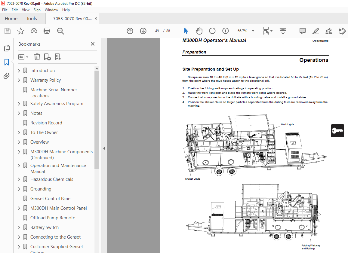
TABLE OF CONTENTS:
TRENCOR M300DH Operation & Safety Instruction Manual – PDF DOWNLOAD
Introduction 2
Foreword 2
Warranty Policy 3
AMERICAN AUGERS WARRANTY POLICY 3
WHO IS COVERED? 3
WHAT IS COVERED? 3
Machine Serial Number Locations 8
Safety Awareness Program 9
Understanding Operation Safety 9
Signal Words 9
Additional Definitions 9
Notes 10
WHAT IS NOT COVERED? 4
Please read and make certain that you understand all safety warnings, operation, and maintenance requirements 6
WHAT MUST THE BUYER DO? 6
Revision Record 11
To The Owner 13
To The Owner 13
Table of Contents 15
Foreword 2 15
Overview 19
Overview 19
M300DH Machine Component 19
1 Genset (if supplied by American Augers) 19
2 Shaker 19
3 Tank Cleanout 19
4 First Cut Tank 19
5 Drain 19
6 Clean Tank 19
7 Offload/Agitate Pump 19
8 Cone Supply/Agitate Pump 19
9 Mixer/Agitate Pump 19
10 Trailer (Optional) 19
M300DH Machine Components (Continued) 20
1 Control Panel 20
2 Genset Control Panel 20
3 Genset Battery Switch 20
4 Work Lights 20
5 Bentonite Mix Hopper and Wash Wand 20
6 Pit Pump 20
7 Pit Pump Storage Location (If no trailer is supplied) 20
8 Chute 20
9 Folding Walkway 20
10 Canopy 20
Operation and Maintenance Manual 21
Ownership of Information 21
Manufacturer Identification Data 21
Machine Identification Data 21
Scope of Document 21
Declaration of Conformity 21
Legal Disclaimer 22
Purpose of Machine 22
Ground Leveling 22
Ambient Conditions 22
Warranty: General Conditions 22
Limitations of Warranty 22
Request for Service/Support 22
Warranty and Service for Diesel Engine/Genset 22
Instruction Manuals 23
Safety Information 25
Safety 25
Safety Regulations and Practices 25
Emergency Procedures 25
Response to Electrical Strike 25
Response to a Gas Strike 26
Response to a Fiber Optic Strike 26
Response to a Communications Line Strike 26
Response to a Sanitary/Storm Sewer and Water Strike 26
Qualification of Personnel 26
Basic Safety Guidelines 27
1 Before using the M300DH all operators should receive thorough training in the use of this equipment This manual should be used as a training tool 27
2 A copy of this manual should remain with the machine and be accessible to all personnel at all times 27
3 Personnel on the jobsite should receive training on safety practices, procedures, safety signs and hazards Operators, support personnel, repair technicians, and visitors should be aware of their responsibilities and any restrictions to their acti 27
4 All new or inexperienced employees should receive a complete orientation to the jobsite and thorough training in their job duties Never allow inexperienced personnel to operate or work near the machine unless they are carefully supervised 27
5 The meaning of the hazard alert signs on the equipment is explained in “Safety Alerts” section beginning on page 36 27
6 Follow all national, state, provincial and local regulations regarding, but not limited to: 27
7 Use required or recommended personal protective equipment which meets applicable standards when operating this machine: 27
8 If a hazardous situation is suspected, stop work until appropriate corrective action is taken 28
9 Use hand signals required for specific jobs Know who has the responsibility for signaling 28
10 Post the location and phone number of the nearest aid station or hospital Have a fire extinguisher and complete first aid kit on site Have at least one of your workers trained in first aid 28
Overhead Hazards 28
Before Starting the Machine 28
Operating Precautions 28
Operator’s Responsibilities 28
Material Handling Precautions 29
Maintenance Precautions 29
Transporting Precautions 29
Trailer Reporting Safety Defects 30
Noise Level Safety 30
Welding Safety 30
Hazardous Chemicals 31
Crystalline Silica (Quartz) Dust Precautions 31
Ladder Safety 32
Refueling Safety 32
Arc Flash Safety 33
Confined Space Entry 34
Danger Zones — Safe Distances 34
Grounding 35
Safety Alerts 36
Machine Controls 39
Controls 39
Safety Switches 39
Genset Control Panel 40
M300DH Main Control Panel 41
Control Panel Functions 42
Offload Pump Remote 43
Battery Switch 44
Service Lights 44
Connecting to the Genset 45
Setup procedure for GENSET 45
1 Ensure GENSET is OFF and not running 45
2 Ensure GENSET Main Breaker is OFF 45
3 Ensure Machine Controls Enclosure is closed and secured 45
4 Ensure Main Breaker in Controls Enclosure is OFF by using the Disconnect Handle 45
5 Ensure all controls on machine are disengaged/deactivated 45
6 Follow proper Lock Out Tag Out procedures 45
7 Connect feeder cables to GENSET following GENSET terminal requirements 45
a Black -Phase A 45
b Red – Phase B 45
c Blue – Phase C 45
d Green – Ground 45
8 Ensure feeder cables are routed securely and away from damage, hazards, and pathways 45
9 Ensure feeder connections to Machine Controls Enclosure are connected matching colors of Feeder ¼ turn fastener with mate and locked securely 45
10 American Augers supplied GENSET includes a shunt trip of the GENSET main circuit breaker This will turn the GENSET Main Circuit breaker OFF if the door of the Machine Controls Enclosure is open while power is applied If alternate GENSET is used 45
11 Ensure proper Grounding of Machine has been performed (See Grounding Section of Manual) 46
12 Follow proper Power Up procedure for the GENSET Adjust GENSET for 480VLL 60 Hz 46
13 Turn GENSET Main Breaker ON 46
14 Turn Machine Controls Breaker ON with Disconnect Handle 46
15 Observe the “OUTPUT ENERGIZED” indicator color on the Machine Controls Enclosure If the indicator illuminates “RED” the three-phase input is incorrect 46
16 Perform the following to resolve this issue: 46
a Completely shut down GENSET and disengage GENSET Main Feed Breaker follow proper Lock Out Tag Out procedures 46
b Swap feeder connections for Phase A and Phase B at GENSET 46
c Turn on GENSET 46
d Turn On GENSET Main Feed Breaker 46
e Verify “OUTPUT ENERGIZED” indicator is illuminated “GREEN” 46
16 After phased connection is verified as correct, proceed with normal operation of Machine 46
17 For shutdown, turn all loads OFF on Machine Controls Enclosure 46
18 Follow proper GENSET shutdown procedure 46
Customer Supplied Genset Option 47
Genset Rating 47
Feeder Interface Connectors 47
Feeder Cable 47
Bonding Cable 47
Notes 48
Preparation 49
Operations 49
Site Preparation and Set Up 49
1 Position the folding walkways and railings in operating position 49
2 Raise the work light post and place the remote work lights where desired 49
3 Connect all components on the drill site with a bonding cable and install a ground stake 49
4 Position the shaker chute so larger particles separated from the drilling fluid are removed away from the machine 49
Pit Pump 50
Crew 50
Hose Connections from Pit Pump to Inlet Port 51
1 Connect the hoses which will bring spent fluid from the pit pump to the M300DH for cleaning 51
2 Fit the female cam and groove fitting onto the male cam and groove coupling on the pit pump 51
3 Push the two levers on the sides of the hose end inward to lock the hose end to the pit pump 51
4 Unroll the hose toward the M300DH inlet port located near the pumps Either inlet port can be used 51
5 Attach the female cam and groove fitting onto the male cam and groove coupling on the inlet port The hose should be laying flat with as few bends as possible Sharp bends in the hose restrict the flow to the first cut shaker on the mud system 51
6 Ensure a cap is installed on the inlet port that is not being used 51
Discharge Hoses 52
Before Operating the Machine 52
Starting the M300DH 53
1 Verify that the ground stake is installed properly 53
2 Check the oil level and coolant level in the engine and the diesel fuel level Start each day with a full tank of ULSD (ultra low sulfur diesel) fuel Never let the diesel engine fuel tank run dry If the tank is dry, bleed the fuel system as outl 53
3 Check the DEF fluid level Do not let the DEF tank run dry 53
4 Confirm that all the fluid connections to and from the machine are correct Check that the valves in the piping are in the correct position to prevent damage to the system when the system is started 53
5 Unplug the block heater, if connected 53
6 Disconnect all battery chargers 53
7 Refer to Setup Procedure for the Genset section 53
8 Pull OUT the engine stop buttons on the Main Control Panel and in the Genset Control Panel The engine will not start if the engine stop button is pushed in 53
9 Switch all controls OFF or put them in neutral 53
10 Turn the Battery switch to the ON position 53
11 Fully open all fuel supply valves 53
12 Follow starting procedures in Attachment 1: Genset Manuals 53
13 After the genset engine is running and warmed up, turn on the generator This enables all switches on the Control Panel 53
Operating the M300DH 54
Preparing the Drilling Fluid 54
Filling Tanks 54
1 Connect a hose to a hydrant or water truck or place the pit pump in a water source such as a lake or river and connect a hose to it 54
2 Connect the opposite end of the hose to one of the inlet ports (see drawing below) 54
3 Cap the unused side of the inlet port piping 54
4 Turn the Shaker control on the Main Control Panel to the START position Release when start is confirmed 54
5 Turn on your pit pump or start the flow of water from the hydrant or water truck Water will be pumped into the inlet port and routed over the shaker, through the screens and into the tank Alternatively, if you are sure the water supply is clean, 54
Adding Bentonite and Agitation 55
Ongoing Drilling Fluid Supply 56
Pumping Fluid to a Directional Drill or Mud Pump 57
Fluid Pumping Checklist 57
Cleaning Drilling Fluid Returns from the Entry Pit 58
1 Be sure the genset engine is running and the generator is ON 58
2 The pit pump should be suspended in the returns pit The hose should be securely connected from the pit pump to the inlet port Open valve for the inlet port, if present 58
3 On the Control Panel, ensure the AC Controls Stop button is not engaged 58
4 Turn the Shaker control to Start Release when start is confirmed 58
5 Turn on your Pit Pump 58
6 Open the butterfly valve on the cone supply pump Turn the Cones control to Start Release when start is confirmed This starts the pump which brings drilling fluid from the First Cut Tank 58
Stopping the Genset Engine 59
1 Turn off all shakers, centrifugal pumps, pit pump, and any auxiliary electrical tools that are running off the genset All these operations can be done at the Control Console 59
2 Go to the genset Disconnect power to the machine Turn off breaker 59
3 If not equipped with a Cool Down Timer, then run the engine for at least 2 minutes to cool down 59
4 Turn the ignition switch to the OFF position 59
5 If required to disconnect the battery, wait at least 25 minutes after engine stop before turning battery switch off 59
End of Job 60
Dismantling the M300DH 60
1 Pump all drilling fluid and clean water out of the tanks All tanks must be empty before moving the M300DH The mud tanks filled with drilling fluid could add as much as 36,000 pounds (16,329 kg) to the weight of the machine This could make the t 60
2 Turn off the genset and genset engine 60
3 Disconnect the pit pump from the plug under the Control Panel (if you have been using) Place the pit pump in the storage location (shown on page 19) For proper lifting procedures, refer to Attachment 4: Manual for the Pit Pump Secure the pit pu 60
4 Switch Battery Switch to Off and perform a Lockout / Tagout before entering the tank 60
5 Clean residual drilling mud out of the tanks Enter the tanks through the cleanout ports on the side of the unit 60
6 Disconnect and clean out hoses 60
7 Dispose of drilling mud following local regulations 60
8 Secure the shaker chute 60
9 Lower and secure work light post DO NOT drive with the work light post extended 60
10 Raise the discharge end walkway Secure in place with pins 60
11 Remove the bolt on stair extension, if using Store and secure for transport 60
12 Rotate the side ladder into transport position Secure in place with pins 60
13 Remove ground stake 60
Operating in Different Climates 61
Operating in Hot Weather 61
Operating in Cold Weather 61
Notes 62
Machine Storage and Transport 63
Storage and Transportation 63
Minimum Storage Space Required 63
Preparations for Storage 63
1 Clean mud and other foreign materials off the machine 63
2 Drain water or bentonite slurry out of the centrifugal pumps and hoses Thoroughly flush the machine Make sure there is no water or drilling fluid in the drilling fluid course If you expect freezing temperatures, pump antifreeze through the system 63
3 Clean the machine as described in “Cleaning” on page 67 63
4 Eliminate sediment and water from the diesel fuel tank 63
5 Fill the fuel tank to prevent condensation and rust 63
6 Position the machine on a level surface 63
7 Follow procedures to turn off the genset and its engine 63
8 Remove all ignition keys and store in a safe place 63
9 Turn the battery switch to the OFF position 63
10 Turn off service lights The lighting circuit is powered as all times If service lights are left on, they will drain the battery 63
11 Lubricate grease points on the machine 63
Removal from Storage 63
Winterizing 64
Transportation 65
1 Clean the machine Pump all drilling fluid and clean water out of the tanks All tanks must be empty before transporting the machine The mud tanks filled with drilling fluid could add as much as 36,000 pounds (16,329 kg) to the weight of the trai 65
2 Turn off the genset and genset engine 65
3 Lockout / Tagout generator set before entering the tanks Clean residual drilling mud out of the tanks You may enter the tanks through the cleanout ports on the side of the unit 65
4 Disconnect and clean out hoses 65
5 Dispose of drilling mud following local regulations Secure the shaker chute 65
6 Lower work light post DO NOT drive with the work light post extended 65
7 Disconnect the pit pump from the plug under the Control Panel (if you have been using) Place the pit pump in the storage location (shown on page 19) For proper lifting procedures, refer to Attachment 4: Manual for the Pit Pump Secure the pit pu 65
8 Switch battery switch to OFF 65
9 Raise the discharge end walkway Secure in place with pins 65
10 Remove the bolt on stair extension, if using Store and secure for transport 65
11 Rotate the side ladder into transport position Secure in place with pins 65
12 Remove the ground stake 65
Lifting the Machine 66
General Maintenance 67
Maintenance 67
Qualification of the Technician 67
Cleaning 67
General Cleaning 68
Cleaning Plastic and Resin Parts 68
Cleaning Hydraulic Connections 68
Cleaning Electrical Connections 68
Welding 69
Tier 4 Diesel Engine 69
Engine and Genset Maintenance 70
Approved Replacement Fluids 70
Approved Replacement Fluids 70
(Ambient temperature 0°F to 110°F [-18°C to 44°C]) 70
Scheduled Maintenance 71
Maintenance Schedule 71
10 Hour Inspection and Maintenance 71
Check Connections 71
Check mechanical, hydraulic, and electrical connections on a daily basis Components to check include are, but not limited to, bolts/nuts, battery cables, and hydraulic hoses 71
Cycle Engine Stop (Disable) Buttons 71
Engine: Check Fuel Level 72
Engine: Check Coolant Level 72
Engine: Check Engine Oil Level 72
Engine: Check Air Filter Service Indicator 72
General Inspections 73
Lubricate Grease Fittings 74
Shaker Angle Adjustment Bolts 74
50 Hour Inspection and Maintenance 75
250 Hour Inspection and Maintenance 76
Check Battery and Battery Fluid Levels 76
500 Hour Inspection and Maintenance 77
2600 Hour Inspection and Maintenance 77
Per Specifications 77
Lubricate Centrifugal Pump Electric Motors 77
Notes 78
Specifications 79
Specifications 79
Machine Dimensions / Weight 79
Generator Set 79
Controls 79
Pump, Mixing/Agitation 79
Pump, Cone Supply 79
Pump, Offload/Agitation 79
Accessories 79
Fluid Capacities 80
Appendix 81
Notes 82
Appendix A: (List of Attachments) 83
Appendix A 83
Appendix B: Soft Starter 84
Appendix B 84
Moving DIM outside of the AC Control Box 84
1 De-energize the system Follow proper Lock Out Tag Out (LOTO) procedures 84
2 Open the AC control box 84
3 Remove the DIM along with the short cable attached to it, on the faulting soft starter by pushing the indented button above the display The cable clip must have the tab pressed to be able to remove it from the soft starter 84
4 Observe the way the cable is bent and installed in the soft starter 84
5 Remove the other end of the short cable in the DIM 84
6 Connect the extension cable that is in the bottom of the chassis to the soft starter Unwrap the cord so can pull from the bottom of the chassis 84
7 Pull the cord from the outside of the chassis so there is enough slack to easily view the removed DIM module 84
8 Plug the end of the cord outside of the AC chassis into the DIM 84
9 Close the cover to the AC control box and tighten If this cover is not closed properly it will cause the circuit breaker in the genset to trip 84
10 Remove the LOTO hardware 84
11 Turn the genset on following proper turn on procedures 84
12 Once powered up look for any fault indications on the DIM Faults can be reset with the DIM module or by cycling genset off and on 84
13 Once troubleshooting is complete reinstall the DIM module by repeating above procedure The soft starter can operate with out the DIM module installed 84
DIM Module 85
Faults 85
Motor Thermal Overload Tripping 86
Overload fault cause 86
Overload fault wait time 86
Sample Declaration of Conformity 87
VIDEO PREVIEW OF THE MANUAL:
S.M


