

Toyota Forklift 6BPU15 Orderpicker Parts Catalog Manual SN 70001 – PDF DOWNLOAD
FILE DETAILS:
Toyota Forklift 6BPU15 Orderpicker Parts Catalog Manual SN 70001 – PDF DOWNLOAD
Language : English
Pages : 252
Downloadable : Yes
File Type : PDF
IMAGES PREVIEW OF THE MANUAL:
DESCRIPTION:
Toyota Forklift 6BPU15 Orderpicker Parts Catalog Manual SN 70001 – PDF DOWNLOAD
to constantly improve our products, therefore, part numbers may continue to change. When ordering parts,
verify part numbers through your Dealer’s Parts Catalog, which is kept up to date. Also note that Illustrations
of assemblies and components may not necessarily conform to the exact installation as they appear on your
truck.
• The model number and serial number of the truck
• Pertinent specifications such as mast height, battery voltage, drive motor type, etc.
• Pertinent name plate data
• Applicable installation or assembly numbers
• Accurate Part Number
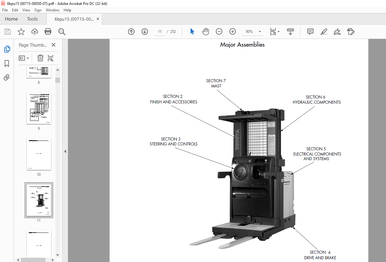
• Use Section 1 to decide where to start your search for information. The overall locator
views define the technical configuration of the Catalog and tie the figures in the
Catalog to the engineering data base.
• Use the Table of Contents to locate assemblies and subassemblies by name.
• Use the Alphabetical Index (by Part Name) and the Numerical Index (by Part Number)
to locate individual parts.
• Determine configuration differences with the “Used On” codes contained within the
Parts List. The “Used On” code attaches a part number to a wide range of design
variables such as operating voltage, battery size, steering type, mast height and
extension speed, fork carriages, color and size of tires, guide wheel specs, etc.
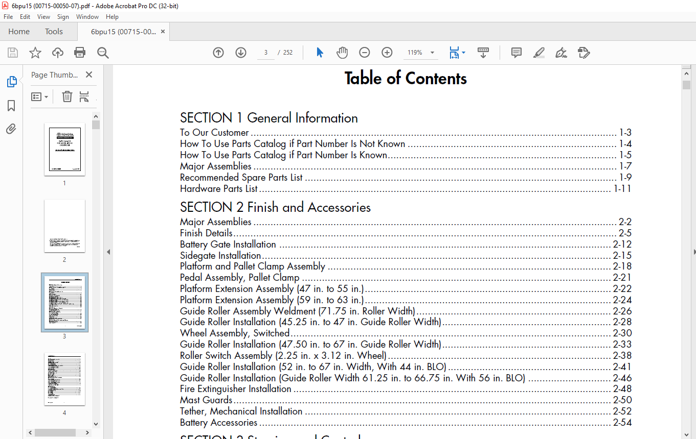
TABLE OF CONTENTS:
Toyota Forklift 6BPU15 Orderpicker Parts Catalog Manual SN 70001 – PDF DOWNLOAD
SECTION 1 General Information
To Our Customer 1-3
How To Use Parts Catalog if Part Number Is Not Known 1-4
How To Use Parts Catalog if Part Number Is Known 1-5
Major Assemblies 1-7
Recommended Spare Parts List 1-9
Hardware Parts List 1-11
SECTION 2 Finish and Accessories
Major Assemblies 2-2
Finish Details 2-5
Battery Gate Installation 2-12
Sidegate Installation 2-15
Platform and Pallet Clamp Assembly 2-18
Pedal Assembly, Pallet Clamp 2-21
Platform Extension Assembly (47 in to 55 in ) 2-22
Platform Extension Assembly (59 in to 63 in ) 2-24
Guide Roller Assembly Weldment (71 75 in Roller Width) 2-26
Guide Roller Installation (45 25 in to 47 in Guide Roller Width) 2-28
Wheel Assembly, Switched 2-30
Guide Roller Installation (47 50 in to 67 in Guide Roller Width) 2-33
Roller Switch Assembly (2 25 in x 3 12 in Wheel) 2-38
Guide Roller Installation (52 in to 67 in Width, With 44 in BLO) 2-41
Guide Roller Installation (Guide Roller Width 61 25 in to 66 75 in With 56 in BLO) 2-46
Fire Extinguisher Installation 2-48
Mast Guards 2-50
Tether, Mechanical Installation 2-52
Battery Accessories 2-54
SECTION 3 Steering and Controls
Steering and Control Components 3-3
Steering Wheel Assembly 3-8
Steer Motor and Gearbox Assembly 3-10
SECTION 4 Drive and Brake
Drive and Brake Components 4-2
Motor and Drive Unit Assembly 4-4
Lower Drive Unit Assembly 4-6
Deadman Brake Components 4-9
Brake Installation 4-12
Brake Assembly 4-14
Deadman Brake Assembly 4-16
Wheel Assembly, Standard, Rounded Black Tire 4-18
SECTION 5 Electrical Components and Systems
Electrical System 5-3
Carriage Electrical Assembly 5-11
Contactor Assembly 5-14
Toyota Model 6BPU15 –
Issued: 5/11/07 ii
Contactor 5-16
Steer Control Assembly, Toyota Tracker 5-18
Display, Controller 5-20
Wire Guide Installation 5-21
Wire Guidance Sensor, Tractor End 5-24
Wire Guidance Sensor, Load End 5-26
Warning Light Installation 5-29
Warning Light Assembly 5-30
Battery Connector Assembly 5-32
Operator Compartment Lights and Fan, Standard 5-35
Light and Fan Assembly, Fluorescent 5-38
Light and Fan Assembly, Incandescent 5-42
Bin Lights Installation 5-47
Bin Light Assembly 5-50
Auxiliary Power Hookup 5-52
Lift Limit Cutout Switch Installation 5-54
Travel Limit Switch Installation 5-57
Lower Limit Switch 5-60
Tractor Heaters, Cold Storage 5-63
Motion Alarm Installation 5-67
Motor Drive, 24 Volt 5-68
Motor, Lift, 24 Volt 5-70
Control Handle Assembly 5-73
SECTION 6 Hydraulic Components
Hydraulic Installation 6-2
Reservoir Assembly 6-4
Lift/Lower Manifold Assembly, Three Stage 6-6
Valve, Lift/Lower, Three Stage 6-8
Lift/Lower Manifold Assembly, Two Stage 6-10
Valve, Lift/Lower, Two Stage 6-12
Lift Pump and Motor Assembly 6-14
Lift Ram, Main Lift, 1 75 inch Diameter 6-16
Lift Ram, Free Lift, 2 5 inch Diameter 6-18
SECTION 7 Mast
Two Stage Mast Assembly 7-2
Three Stage Mast Assembly 7-7
Two and Three Stage Mast Cables, Hoses and Pulleys 7-13
Fork Assembly, Standard 7-22
End Cap Pulley Assembly 7-24
Pulley Assembly 7-28
Pulley Assembly 7-29
Pulley Assembly 7-30
Bumper Assembly 7-31
Load Wheel Assembly 7-32
Alphabetical Parts Index A-1
Numerical Parts Index B-1
VIDEO PREVIEW OF THE MANUAL:
PLEASE NOTE:
- This is not a physical manual but a digital manual – meaning no physical copy will be couriered to you. The manual can be yours in the next 2 mins as once you make the payment, you will be directed to the download page IMMEDIATELY.
- This is the same manual used by the dealers inorder to diagnose your vehicle of its faults.
- Require some other service manual or have any queries: please WRITE to us at [email protected]
S.V


