

TCM 275BN Tractor Shovel Parts Manual 897A – PDF DOWNLOAD
FILE DETAILS:
TCM 275BN Tractor Shovel Parts Manual 897A – PDF DOWNLOAD
Language : English
Pages : 264
Downloadable : Yes
File Type : PDF
Size: 7.2 MB
IMAGES PREVIEW OF THE MANUAL:


VIDEO PREVIEW OF THE MANUAL:
TABLE OF CONTENTS:
TCM 275BN Tractor Shovel Parts Manual 897A – PDF DOWNLOAD
A Engine Group
Fig. 1 Engine Mount Parts
Fig. 2 Engine Control Linkage
Fig. 3 Radiator
Fig. 4 Fuel Tank and Line
Fig. 5 Air Cleaner and Muffler
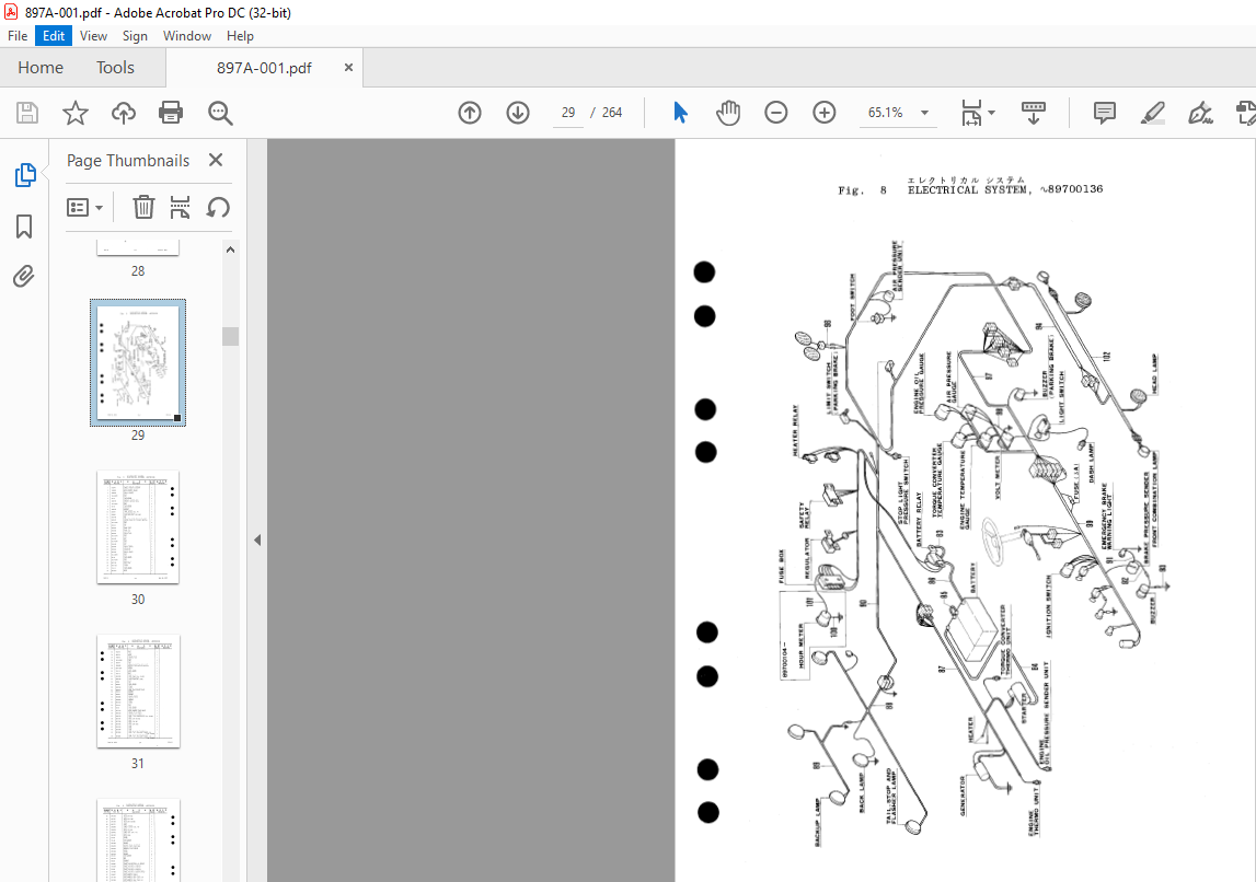
Fig. 6 Instrument Panel, ~89700136
Fig. 6A Instrument Panel, 89700137
Fig. 7 Battery and Battery Mount
SA Electrical System, 89700137
Fig. 1 Engine Mount Parts
Fig. 2 Engine Control Linkage
Fig. 3 Radiator
Fig. 4 Fuel Tank and Line
Fig. 5 Air Cleaner and Muffler
Fig. 6 Instrument Panel, ~89700136
Fig. 6A Instrument Panel, 89700137
Fig. 7 Battery and Battery Mount
SA Electrical System, 89700137
B Drive System Group
Fig. 9 Drive Axle-Front
Fig. 10 Differential and Carrier-Front
Fig. 11 Drive Axle-Rear
Fig. 12 Differential and Carrier-Rear
Fig. 13 Planet Carrier-Front and Rear
Fig. 14 Brake-Front and Rear
Fig. 15 Wheel and Tire-Front and Rear
Fig. 16 Electrical System, ~89700136
Fig. 9 Drive Axle-Front
Fig. 10 Differential and Carrier-Front
Fig. 11 Drive Axle-Rear
Fig. 12 Differential and Carrier-Rear
Fig. 13 Planet Carrier-Front and Rear
Fig. 14 Brake-Front and Rear
Fig. 15 Wheel and Tire-Front and Rear
Fig. 16 Electrical System, ~89700136
Propeller Shaft
Midmount Bearing
Transmission
Transmission Case and Internal Tubing
Fig. 20 Transmission Shaft Group-Input
Fig. 21 Transmission Shaft Group-Reverse
Fig. 22 Transmission Shaft Group-Idler
Fig. 23 Transmission Shaft Group-1st and 3rd
Fig. 24 Transmission Shaft Group-2nd and 4th
Fig. 25 Transmission Shaft Group-Output
Fig. 26 Transmission Clutch Group-1st and 2nd
Fig. 27 Transmission Clutch Group-Input, Reverse, 3rd and 4th
Fig. 28 Transmission Speedometer Drive System
Fig. 29 Transmission Control Valve
Fig. 30 Torque Converter
Fig. 31 Torque Converter Pressure Regulating Valve
Fig. 32 Torque Converter Accessory
C Control System Group
Steering Gear Mounting
Steering Gear
Steering Drag Link
Fig. 36 Cylinder-Steering
Fig. 37 Brake Control Line, ~89700136
Fig. 37A Brake Control Line, 89700137
Fig. 38 Parking Brake Control
Fig. 39 Parking Brake Lever
Fig. 40 Transmission Control Linkage
Fig. 40A Transmission Control Linkage, 89700137
D Chassis Group
Fig. 41 Frame
Fig. 42 Hood and Grill
Cockpit and Seat, ~89700136
Cockpit and Seat, 89700137
Fig. 41 Frame
Fig. 42 Hood and Grill
Cockpit and Seat, ~89700136
Cockpit and Seat, 89700137
E Hydraulic System Group
Fig. 44 Pump-Main
SH Valve
Pump-Steering
SD Valve
Valve and Valve Control, ~89700136
Valve and Valve Control, 89700137
Control Valve-Bucket Section and Inlet Section, ~89700102
Fig. 50 Control Valve-Boom Section and Outlet Section, ~89700102
Fig. 51 Main Valve-Inlet Section and Outlet Section
Fig. 52 Main Valve-Bucket Section
Fig. 58 Hydraulic System-Transmission and Torque Converter
F Loading System Group
Cylinder-Boom
Fig. 60 Cylinder-Bucket
Fig. 61 Long Boom, Bellcrank, Pushrod and Bucket
Bucket (for Long Boom)
Fig. 63 Short Boom, Bellcrank, Pushrod and Bucket
Bucket (for Short Boom)
Fig. 65 Bucket Leveler
Cylinder-Boom
Fig. 60 Cylinder-Bucket
Fig. 61 Long Boom, Bellcrank, Pushrod and Bucket
Bucket (for Long Boom)
Fig. 63 Short Boom, Bellcrank, Pushrod and Bucket
Bucket (for Short Boom)
Fig. 65 Bucket Leveler
G Others
Piping-Grease
Name Plate and Decal, ~89700136
Name Plate and Decal, 89700137
Clip
Tools
Index
Piping-Grease
Name Plate and Decal, ~89700136
Name Plate and Decal, 89700137
Clip
Tools
Index
PLEASE NOTE:
- This is the same manual used by the DEALERSHIPS to SERVICE your vehicle.
- The manual can be all yours – Once payment is complete, you will be taken to the download page from where you can download the manual. All in 2-5 minutes time!!
- Need any other service / repair / parts manual, please feel free to contact us at heydownloadss @gmail.com . We may surprise you with a nice offer
S.V


