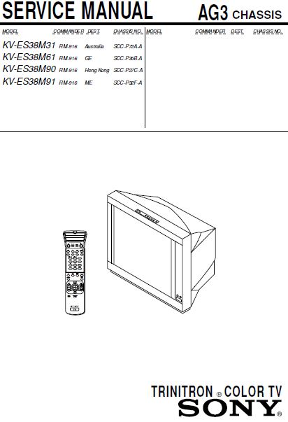
REPAIR MANUAL SONY KV ES38M31 KV ES38M61 TRINITRON COLOR TV PDF DOWNLOAD

Section Title Page Section Title Page
SELF DIAGNOSTIC FUNCTION……………………… 4
1. GENERAL ……………………………………………….. 7
2. DISASSEMBLY
2-1. Rear Cover Removal ………………………………………. 33
2-2. Speaker Box Removal ……………………………………. 33
2-3. H2 Board Removal ………………………………………… 33
2-4. Chassis Assy Removal ……………………………………. 34
2-5. Service Position …………………………………………….. 34
2-6. DH Board Removal ……………………………………….. 34
2-7. J Board Removal ……………………………………………. 34
2-8. B3, D1 and E Boards Removal ……………………….. 35
2-9. A and D Boards Removal ……………………………….. 35
2-10. H1 Boards Removal ……………………………………….. 35
2-11. F2 Board Removal …………………………………………. 35
2-12. Demagnetization Coil Removal ………………………. 36
2-13. Top Switch Removal
(H3 Board Removal) ………………………………………. 36
2-14. G2 Lead Removal ………………………………………….. 36
2-15. Picture Tube Removal ……………………………………. 37
2-16. Frame Sub-Assy Disassembly …………………………. 37
3. SERVICE JIG
3-1. Jigs Required for Servicing …………………………….. 40
4. CIRCUIT BOARDS LOCATION ………………… 40
5. SET-UP ADJUSTMENTS
5-1. Beam Landing ……………………………………………….. 41
5-2. Convergence Adjustment ………………………………… 42
5-3. Focus Adjustment ………………………………………….. 44
5-4. Neck Assy Twist Adjustment ………………………….. 44
5-5. G2 (Screen) and White Balance Adjustment …….. 45
6. CIRCUIT ADJUSTMENTS
6-1. Adjustment with Commander …………………………. 46
6-2. Asjustment Method ……………………………………….. 46
6-3. Picture Quality Adjustment …………………………….. 59
6-4. Deflection Adjustment ……………………………………. 60
6-5. A Board Ajustment After IC003 (Memory)
Replacement …………………………………………………. 62
6-6. Picture Distortion Adjustment …………………………. 63
7. DIAGRAMS
7-1. Block Diagram ………………………………………………. 65
7-2. Schematic Diagram ………………………………………… 70
(1) Schematic Diagram of A Board ………………….. 77
(2) Schematic Diagram of D Board …………………. 78
(3) Schematic Diagram of D1 Board ……………….. 79
(4) Schematic Diagram of C Board ………………….. 80
(5) Schematic Diagram of E Board ………………….. 81
(6) Schematic Diagram of J Board …………………… 82
(7) Schematic Diagrams of VM and F1 Boards …. 83
(8) Schematic Diagrams of H1, H3, F2 and
SP Boards ………………………………………………… 84
(9) Schematic Diagrams of DH and H2 Boards … 85
(10) Schematic Diagram of A1 Board………………. 86
(11) Schematic Diagram of BC4 Board ……………. 97
(12) Schematic Diagram of V Board………………… 98
(13) Schematic Diagram of B3 Board ………………. 99
7-3. Voltage Measurement …………………………………… 114
7-4. Waveforms ………………………………………………….. 127
7-5. Printed Wiring Board and Parts Location ……….. 131
7-6. Semiconductors …………………………………………… 147
8. EXPLODED VIEWS
8-1. Speaker Bracket …………………………………………… 150
8-2. Chassis ……………………………………………………….. 151
8-3. Picture Tube ………………………………………………… 152
9. ELECTRICAL PARTS LIST ……………………. 153
PLEASE NOTE:
- This is not a physical manual but a digital manual – meaning no physical copy will be couriered to you. The manual can be yours in the next 2 mins as once you make the payment, you will be directed to the download page IMMEDIATELY.
- This is the same manual used by the dealers inorder to diagnose your vehicle of its faults.
- Require some other service manual or have any queries: please WRITE to us at heydownloadss@gmail.com


Reviews
There are no reviews yet.