

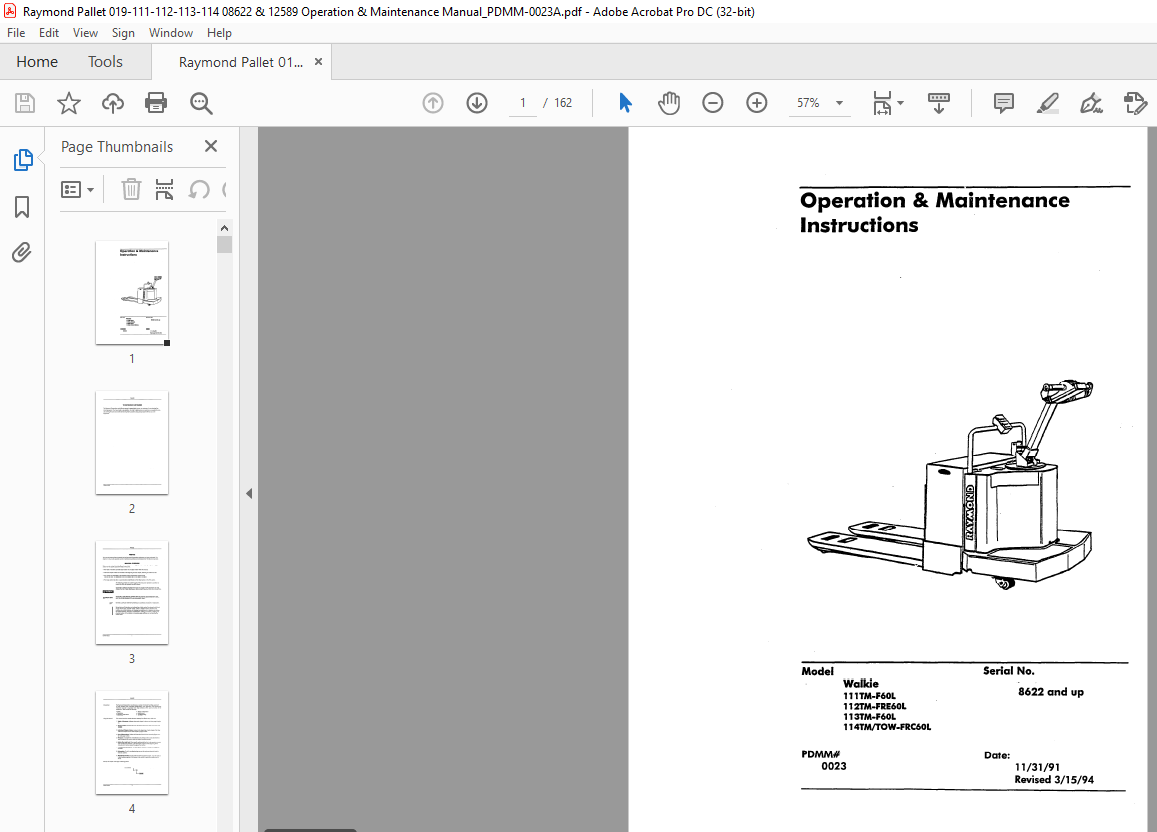
Raymond Walkie 111TM-F60L 112TM-FRE60L 113TM-F60L 114TM TOW-FRC60L Operation & Maintenance Instructions Manual SN8622 and up – PDF DOWNLOAD
FILE DETAILS:
Raymond Walkie 111TM-F60L 112TM-FRE60L 113TM-F60L 114TM TOW-FRC60L Operation & Maintenance Instructions Manual SN8622 and up – PDF DOWNLOAD
Language : English
Pages : 162
Downloadable : Yes
File Type : PDF
Size: 9.96 MB
DESCRIPTION:
Raymond Walkie 111TM-F60L 112TM-FRE60L 113TM-F60L 114TM TOW-FRC60L Operation & Maintenance Instructions Manual SN8622 and up – PDF DOWNLOAD
TO RAYMOND CUSTOMERS
The Raymond Corporation would like to express its appreciation to you, our customer, for purchasing Raymond equipment. You have made a wise selection. In order to better serve our customers, we supply this manual outlining the core and routine service required to provide a long and productive life for your new equipment.
PREFACE
This manual presents factual material on The Raymond Corporation equipment you have purchased. The object is to insure safe operation and/or maintenance practices and procedures for this Raymond product.
MANUAL OVERVIEW
This manual consists of both Maintenance section and Parts Catalog (P/C) for the specific equipment listed on
the cover.
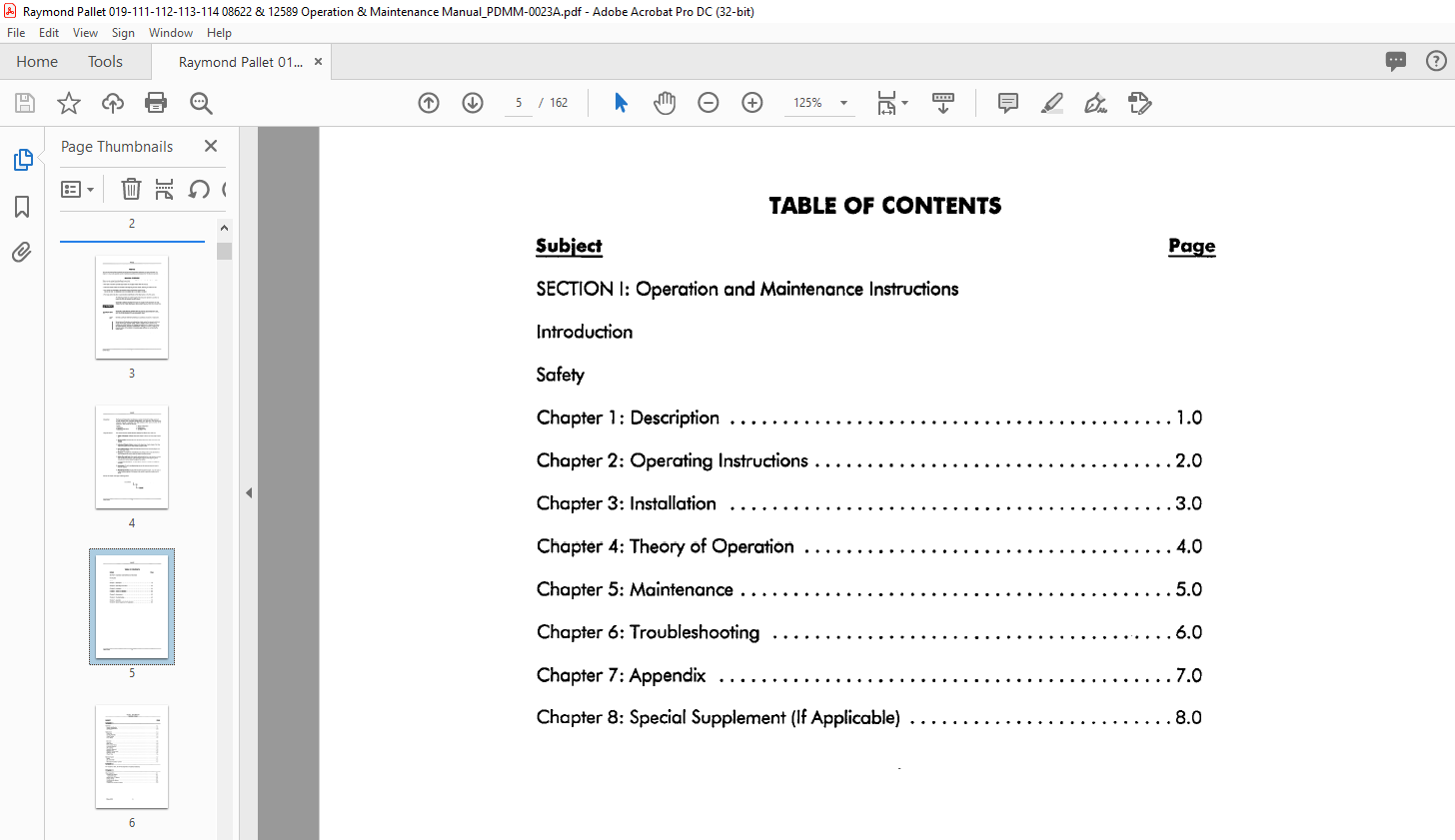
• The Table of Contents provides easy location of all subject matter within the manual.
• Individual chapter indexes are located at the beginning of each chapter, following the reference tabs.
• Any chapter not applicable to the particular piece of equipment covered in this manual will state
“Not Applicable” after the chapter title on the Table of Contents.
• The large section tabs allow a quick location identification for each section.
TABLE OF CONTENTS:
Raymond Walkie 111TM-F60L 112TM-FRE60L 113TM-F60L 114TM TOW-FRC60L Operation & Maintenance Instructions Manual SN8622 and up – PDF DOWNLOAD
SECTION I: Maintenance Instructions
Introduction
Safety
Chapter l : Description 10
Chapter 3: Installation 30
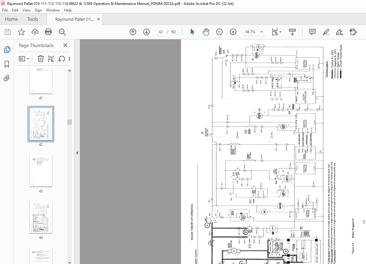
Chapter 4: Theory of Operation 40
Chapter 5: Maintenance 50
Chapter 6: Troubleshooting 60
Chapter 7: Appendix 7 0
Overview
Model Identification
Vehicle Specifications
Description
Mechanical
Drive Unit
Handle Assembly
Coast Control
Jogging
Drum Brake
Hydraulic
General
Pressure Relief Valve
Flow Control Valve
Lowering Solenoid
Lift Cylinders
Hydraulic Reservoir
Breather Cap
Hydraulic Pump Motor
Hydraulic Pump
Check Valve
Hydraulic Components
Electrical System
Battery
Drive Motor
Contadors
Lift Limit Switch
Motor Controller
Model 111
Model 112
Model 113
Model 114
Visual Inspection
Checking the Battery
Hydrometer Use
Adding Water To Battery
Voltage Check
Conneding the Battery
Lubrication
Checking the Hydraulic System
Cold Storage Conditioning
Oasses Of Cold Storage
Operational Checks
Brake
Fork/Lift Linkage
Emergency Reverse Switch
Coast Control
Jogging
Receiving lnspedion Guide
Break-In Period
Introduction
Motors
Pump
Battery
Decal Placement
Transistor Control
Overview
Presentation
Outline
System Overview
Transistor Control
Current Limiting
Low Voltage Cutback
Thermal Protedion
Runaway Protedion
Static Return to Neutral Protedion
Plugging
Controller Keyswitch Input
Controller Thumbwheel Throttle Inputs
“Emergency Reverse” Plug Breaking Inhibit
Control Module
Tradion System
Battery Plugged IN
Battery Plugged IN/Keyswitch Turned To ON
Battery Plugged IN/Keyswitch Turned ON/Deadman Swich Closed
Diredional/Speed Control Forward
Directional/Speed Control-High Speed (FORWARD ONLY)
Emergency Reverse
Plugging
Jog Forward (Jog Relay or Jumper Board)
Lift/Lower System
Lift
Lower
Scheduled Maintenance
Lubrication and Maintenance Guide
Daily or Every 8 Operating Hours, Whichever Occurs First
Weekly or Every 50 Operating Hours, Whichever Occurs First
Monthly or Every 200 Operating Hours, Whichever Occurs First
Every 500 Hours
Semiannually or Every 1,000 Hours, Whichever Occurs First
Welding Precautions
WALKIE TM
TABLE OF CONTENTS
SUBJECT
Lubrication and Maintenance Guide
Lubrication
Hydraulic System Oil
Power Section
Drive Unit
Drive Unit Service
Drive Housing Lubrication
Drive Housing Vent Plug
Drive Housing Steering Bearing
Mechanical
Drive Unit Assembly
Drive Unit Tooth Pattern
Drive Gear Case Data
Gear Checking Procedure
Drive Unit Installation
Brake
Daily lnspedion
After Every 500 Hours of Operation
Doily lnspedion 111 /112
After Every 500 Hours of Operation 113/114
Brake Adjustment 111 /112
Brake Adjustment 113/114
Deadman Switch Adjustment
Handle Return Spring Adjustment
Coast Control Adjustment
Drive Wheel
Daily Inspection
After Every 50 Hours of Operation
After Every 200 Hours of Operation
Cushion Drive Tire Replacement
Load Wheels
Daily Inspection
After Every 50 Hours of Operation
After Every 500 Hours of Operation
Wheel Replacement
Pallet Entry Wheels (8000# Models Only) Daily Inspection
After Every 50 Hours of Operation
After Every 500 Hours of Operation
Wheel Replacement
Fork Height Adjustment (6000# Model)
Lowered Fork Height •
Fork Height Adjustment (8000# Model)
Revised 6/30/95
Casters
Daily lnspedion
Fork And Linkage
After Every 50 Hours of Operation
lift limit Switch Adjustment
Hydraulic
Hydraulic System
lnspedion
500 Hours
Hydraulic Reservoir
WALKIE TM
TABLE OF CONTENTS
Checking and Adjusting Hydraulic Pump Relief Valve Pressure
Relief Valve Setting
Hydraulic Reservoir
lnspedion Every 8 Hours
Lift Cylinders Service
Oil leakage Wiper Seal
lnspedion Every 200 Hours
Cleaning Breather Cop
lnspedion Every 1,000 Hours
Eledrical
Battery
Eledrolyte level
Specific Gravity
Battery Exterior
Battery Charging
Battery Storage
Motors
lnspedion
Brushes
Commutator
lnspedion
Servicing
High Mica
Motor Stud Terminals
Drive Motor General Data
Drive Motor lnspedion
Drive Motor Removal
Drive Motor Replacement
lift Motor General Data
lnspedion
Removal
Tradion System Adjustments
Potentiometer Adjustments
Current Limit Setting
Plug Current Adjustment
Acceleration Adjustment
Revised 6/30/95
Potentiometer
Deadman Switch Adjustment
Contadors
Cleaning
lnspedion
Tip lnspedion
Contador Table
Contador Coil Replacement
WALKIE TM
TABLE OF CONTENTS
Replacement Of Contactor Tips, Insulation And/or Core And Rod Assembly
Contactor Disassembly /Reassembly
Checking Components
Diodes
Plug Diode Test
Throttle Potentiometer Setting
Example
Turtle Speed Module (DA2)
Test/Adjustment
Replacement
Emergency Reverse Module (DA 1)
Test Procedure
Jog Relay or Jumper Board
Testing Other Eledrical Components
Overview
Field Replacement Units (FRU)
Wiring lnspedion Procedure
Tradion System Problems 64
Truck Does Not Run – Diredional Contadors Do Not Close 64
Trude Does Not Run – Directional Contactors Energize 66
Truck Runs In One Direction Only – Opposite Diredion Contador Does Not Energize 67
Truck Runs In One Direction Only – Diredional Contadors Work Normally 68
Truck Does Not Run In High Speed (Forward only) 69
Plugging Does Not Operate Properly 610
Truck Does Not Accelerate Properly 6 10
Emergency Reverse Module Checks OK No Reverse Travel With S25 Depressed 612
Lift/Lower Problems
Forks Do Not Lift When Lift Button Is Pushed
Forks Do Not Lower When Lower Button Is Pushed
Lubrication Chart
Standard Torque Data for Bolts
Conversion Table
Decimal Equivalent Chart
Revised 6/30/95
PDMM-0039 V
SUBJECT
Schematic Legend
Electrical Schematic
Model 111
Model 112
Model 113
Model 114
Hydraulic Schematic
Harness/Hour/Battery Meter
Appendix A – Alphabetical Index
Revised 6/30/95
IMAGES PREVIEW OF THE MANUAL:
VIDEO PREVIEW OF THE MANUAL:
PLEASE NOTE:
- This is the SAME exact manual used by your dealers to fix your vehicle.
- The same can be yours in the next 2-3 mins as you will be directed to the download page immediately after paying for the manual.
- Any queries / doubts regarding your purchase, please feel free to contact [email protected]
S.M


