

Perkins 1204E-E44TA and 1204E-E44TTA Industrial Engines Disassembly & Assembly Manual
TABLE OF CONTENTS:
Perkins 1204E-E44TA and 1204E-E44TTA Industrial Engines Disassembly & Assembly Manual
Disassembly and Assembly Section
Fuel Priming Pump – Remove and Install (Electric
Fuel Lift Pump (EFLP)) 5
Flow Control Valve – Remove and Install 7
Fuel Filter Base – Remove and Install (Twin
Secondary Fuel Filter) 10
Fuel Filter Base – Remove and Install (Single
Secondary Fuel Filter) 13
Water Separator and Fuel Filter (Primary) – Remove
and Install 17
Fuel Manifold (Rail) – Remove and Install 19
Relief Valve (Fuel) – Remove and Install 21
Fuel Injection Lines – Remove 22
Fuel Injection Lines – Install 24
Exhaust Cooler (NRS) – Remove and Install (Top
mounted Turbocharger) 27
Exhaust Cooler (NRS) – Remove and Install (Side
mounted Turbocharger) 30
Exhaust Cooler (NRS) – Remove and Install (Twin
Turbocharger) 33
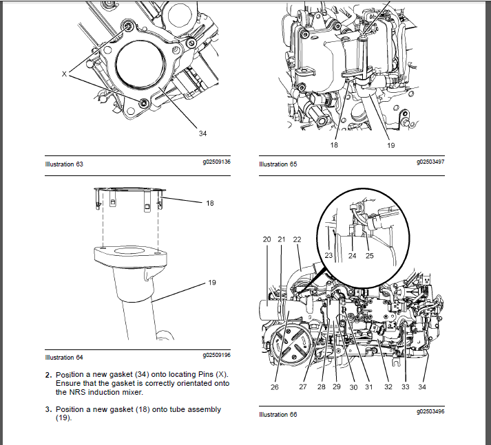
Inlet Air Control – Remove (NRS Induction Mixer) 37
Inlet Air Control – Install (NRS Induction Mixer) 38
Fuel Injection Pump – Remove 41
Fuel Injection Pump – Install 43
Fuel Injection Pump Gear – Remove 45
Fuel Injection Pump Gear – Install 45
Electronic Unit Injector – Remove 46
Electronic Unit Injector – Install 49
Turbocharger – Remove (First Stage
Turbocharger) 51
Turbocharger – Remove (Top Mounted Turbocharger
) 53
Turbocharger – Remove (Side Mounted
Turbochargers) 55
Turbocharger – Remove (Second Stage
Turbocharger) 56
Turbocharger – Install (First Stage Turbocharger) 57
Turbocharger – Install (Top Mounted Turbocharger
) 60
Turbocharger – Install (Side Mounted
Turbochargers) 62
Turbocharger – Install (Second Stage
Turbocharger) 63
Wastegate Solenoid – Remove and Install 66
Exhaust Back Pressure Valve – Remove and
Install 68
Flexible Exhaust Pipe – Remove and Install 70
Exhaust Manifold – Remove and Install (Twin
Turbocharger Exhaust manifold) 73
Exhaust Manifold – Remove and Install (Single
Turbocharger Exhaust Manifold) 76
Exhaust Elbow – Remove and Install 80
Exhaust Elbow – Remove and Install (Top Mounted
and Side Mounted Turbocharger Exhaust
Elbow) 81
Diesel Particulate Filter – Remove 82
Diesel Particulate Filter – Install 85
Inlet and Exhaust Valve Springs – Remove and
Install 88
Inlet and Exhaust Valves – Remove and Install 91
Engine Oil Filter Base – Remove and Install 94
Engine Oil Cooler – Remove 95
Engine Oil Cooler – Install 96
Engine Oil Pump – Remove 97
Engine Oil Pump – Install 98
Water Pump – Remove 99
Water Pump – Install 100
Water Temperature Regulator – Remove and Install
102
Flywheel – Remove 103
Flywheel – Install 104
Crankshaft Rear Seal – Remove 105
Crankshaft Rear Seal – Install 106
Flywheel Housing – Remove and Install (Wet Back
End Housing) 107
Flywheel Housing – Remove and Install (Standard
Housing) 110
Crankshaft Pulley – Remove and Install 112
Crankshaft Front Seal – Remove and Install 113
Crankshaft Front Seal – Remove and Install
(Crankshaft Front Seal for Heavy Duty Front
Cover) 115
Front Cover – Remove and Install 116
Front Cover – Remove and Install (Heavy Duty Front
Cover) 117
Gear Group (Front) – Remove and Install 118
Gear Group (Front) – Remove and Install (Heavy
Duty Gear Group (Front)) 124
Idler Gear – Remove 131
Idler Gear – Install 133
Housing (Front) – Remove 135
Housing (Front) – Remove (Heavy Duty Housing
(Front)) 137
Housing (Front) – Install 138
Housing (Front) – Install (Heavy Duty Housing
(Front)) 141
Accessory Drive – Remove and Install (Accessory
Drive SAE “B”) 143
Accessory Drive – Remove and Install (Accessory
Drive SAE “A”) 146
Crankcase Breather – Remove 148
Crankcase Breather – Install 149
Valve Mechanism Cover – Remove and Install 151
Rocker Shaft and Pushrod – Remove 153
Rocker Shaft – Disassemble 155
Rocker Shaft – Assemble 156
Rocker Shaft and Pushrod – Install 157
Cylinder Head – Remove 161
Cylinder Head – Install 164
Lifter Group – Remove and Install (Hydraulic Lifter
Group) 168
Camshaft – Remove and Install 169
Camshaft Gear – Remove and Install 172
Camshaft Bearings – Remove and Install 176
Engine Oil Pan – Remove and Install (Aluminum and
Pressed Steel Oil Pans) 177
Engine Oil Pan – Remove and Install (Cast Iron Oil
Pan) 181
Balancer – Remove 184
Balancer – Install 185
4 KENR9125
Table of Contents
Piston Cooling Jets – Remove and Install 188
Pistons and Connecting Rods – Remove 189
Pistons and Connecting Rods – Disassemble 190
Pistons and Connecting Rods – Assemble 192
Pistons and Connecting Rods – Install 193
Connecting Rod Bearings – Remove (Connecting
Rods in Position) 195
Connecting Rod Bearings – Install (Connecting Rods
in Position) 196
Crankshaft Main Bearings – Remove and Install
(Crankshaft in Position) 197
Crankshaft – Remove 201
Crankshaft – Install 204
Crankshaft Timing Ring – Remove and Install 207
Crankshaft Gear – Remove and Install 208
Crankshaft Gear (Balancer Drive) – Remove and
Install 209
Bearing Clearance – Check 210
Refrigerant Compressor – Remove and Install 211
Atmospheric Pressure Sensor – Remove and
Install 214
Camshaft Position Sensor – Remove and Install 215
Crankshaft Position Sensor – Remove and
Install 216
Coolant Temperature Sensor – Remove and
Install 217
Engine Oil Pressure Sensor – Remove and Install
218
Fuel Temperature Sensor – Remove and Install 219
Soot Antenna – Remove and Install 221
Temperature Sensor (DPF) – Remove and
Install 222
Temperature Sensor (Cooled Exhaust Gas) – Remove
and Install 223
Pressure Sensor (Cooled Exhaust Gas) – Remove
and Install (NRS Inlet and Outlet Pressure
Sensors) 224
Boost Pressure Sensor – Remove and Install 226
Inlet Manifold Temperature Sensor – Remove and
Install 227
Glow Plugs – Remove and Install 228
Alternator Belt – Remove and Install 229
Idler Pulley – Remove and Install (Grooved Idler
Pulley) 231
Idler Pulley – Remove and Install (Flat Idler
Pulley) 231
Belt Tensioner – Remove and Install 232
Fan – Remove and Install 233
Fan Drive – Remove and Install 234
Electronic Control Module – Remove 235
Electronic Control Module – Install 239
Alternator – Remove 242
Electric Starting Motor – Remove and Install 245
Alternator – Install 246
Air Compressor – Remove and Install (Twin Cylinder
Compressor) 249
Air Compressor – Remove and Install (Single
Cylinder) 255
Index Section
Index 261
VIDEO PREVIEW OF THE MANUAL:

IMAGES PREVIEW OF THE MANUAL:

PLEASE NOTE:
- This is not a physical manual but a digital manual – meaning no physical copy will be couriered to you. The manual can be yours in the next 2 mins as once you make the payment, you will be directed to the download page IMMEDIATELY.
- This is the same manual used by the dealers inorder to diagnose your vehicle of its faults.
- Require some other service manual or have any queries: please WRITE to us at [email protected]


Zahir Justin –
SEEMS EASY ENOUGH