

MTU Diesel Engine 12 V 2000 M84 16 V 2000 M84 12 V 2000 M94 16 V 2000 M94 (Common Rail) Maintenance Manual MS22045-00E PDF DOWNLOAD
FILE DETAILS:
MTU Diesel Engine 12 V 2000 M84 16 V 2000 M84 12 V 2000 M94 16 V 2000 M94 (Common Rail) Maintenance Manual MS22045-00E PDF DOWNLOAD
Language : English
Pages : 298
Downloadable : Yes
File Type : PDF
IMAGES PREVIEW OF THE MANUAL:
VIDEO PREVIEW:
DESCRIPTION:
MTU Diesel Engine 12 V 2000 M84 16 V 2000 M84 12 V 2000 M94 16 V 2000 M94 (Common Rail) Maintenance Manual MS22045-00E PDF DOWNLOAD
GENERAL INFORMATION:
Important Notes
Prerequisites for Maintenance Work and General Assembly Instructions
Contents include:
- If maintenance work is carried out by the customer, the following needs to be ensured:
- Observance of safety regulations.
- Deployment of trained and qualified personnel.
- Suitable shop equipment and general tools.
- Suitable testing equipment.
- Approved special tools.
- Always use new sealing and securing elements for assembly.
- Components that come into contact with oil, fuel, engine coolant, and combustion air must be clean.
- Prior to assembly, clean components with “Special cleanness” requirement (e.g., oil and fuel-carrying parts) using suitable cleaning methods and then check for cleanness.
- Remove any packaging from components immediately before assembly.
Do not wash elastomer components (e.g., rubber, etc.) using diesel fuel, solvent, or cold cleaner.
- Remove any oil or fuel film. Wipe parts down with a dry cloth to clean them.
- Do not paint elastomer components, such as engine mounts, damping elements, clutches, and V-belts. Only install them after painting the engine or cover them prior to painting.
- Radial shaft seals that have been treated with oil by the manufacturer have a defined moisture expansion on delivery. Prior to installation, they may only be cleaned using abrasion-proof paper (not washed).
- If not otherwise specified, the surfaces of parts that slide on each other should be moistened with SAE 30 engine oil.
If not otherwise specified, O-rings and surfaces (bores or shafts) that slide along them during installation should be coated with grease.
- During the assembly of O-rings with counterrings in coolant pumps, observe the assembly instructions.
- After assembling O-rings in the grooves on shafts, push a rounded scriber under the O-ring in circumferential direction if the O-ring diameter is large enough. The O-ring may not be damaged.
- Prior to assembling shaft seals:
- Coat shaft and sealing lip of shaft seal with grease and coat shaft running surface with thin-film lubricant or SAE 30 engine oil.
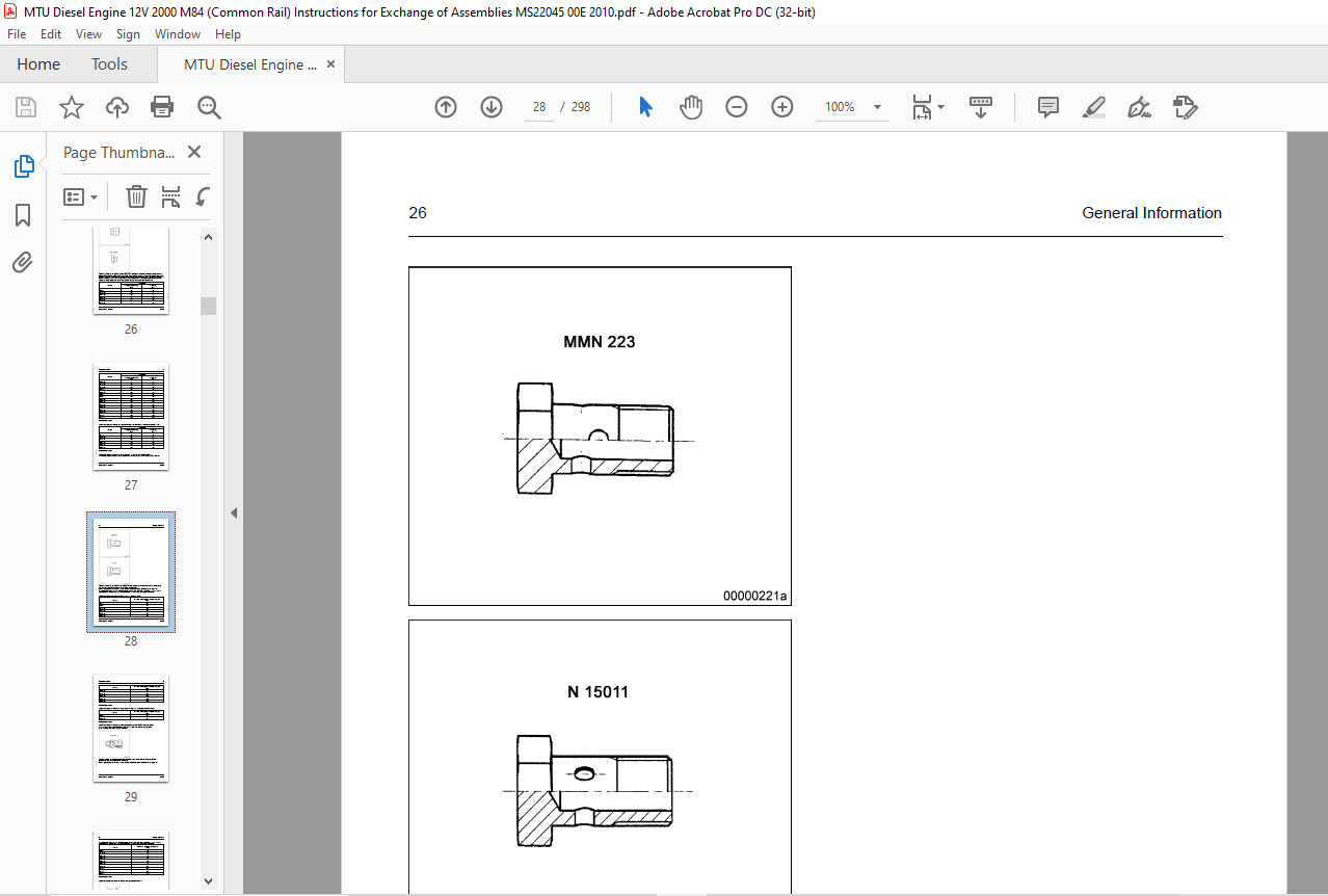
- If no other information is specified on the drawing, coat the outer surface of mounting bores on metal outer liners with surface sealant. Coat the outer surface of elastomer outer liners or combined metal/elastomer outer liners with ethanol.
TABLE OF CONTENTS:
MTU Diesel Engine 12 V 2000 M84 16 V 2000 M84 12 V 2000 M94 16 V 2000 M94 (Common Rail) Maintenance Manual MS22045-00E PDF DOWNLOAD
Title..........................................................................................................  1
Table of Contents..............................................................................................  3
1 General Information..........................................................................................  7
	1.1 Important Notes........................................................................................  7
		1.1.1 Prerequisites for maintenance work and general assembly instructions.............................  7
			Prerequisites for maintenance work.................................................................  7
			General assembly instructions......................................................................  7
	1.2 General Provisions.....................................................................................  9
		1.2.1 General Instructions.............................................................................  9
			General............................................................................................  9
			Correct use........................................................................................  9
			Modifications or conversions.......................................................................  9
			Spare parts........................................................................................  9
			Reworking components...............................................................................  9
		1.2.2 Personnel and organizational requirements ....................................................... 10
			Personnel requirements............................................................................. 10
			Organizational measures............................................................................ 10
			Working clothes and protective equipment........................................................... 10
		1.2.3 Safety precautions when working on the engine.................................................... 11
			Safety precautions when putting the equipment into operation....................................... 11
			Safety requirements for operators.................................................................. 11
			Engine operation................................................................................... 11
			Maintenance and repair............................................................................. 11
			Welding work....................................................................................... 12
			Hydraulic installation and removal................................................................. 12
			Working on electrical/electronic assemblies........................................................ 13
			Working with laser equipment....................................................................... 13
			Operation of electrical equipment.................................................................. 13
		1.2.4 Auxiliary materials, fire prevention and environmental pro....................................... 14
			Fire prevention.................................................................................... 14
			Noise.............................................................................................. 14
			Environmental protection........................................................................... 14
			Auxiliary materials, fluids and lubricants......................................................... 14
			Lead............................................................................................... 14
			Acid and alkaline solutions........................................................................ 14
			Paints, enamels and varnishes...................................................................... 14
			Liquid nitrogen.................................................................................... 15
			Compressed air..................................................................................... 15
			Used oil........................................................................................... 15
		1.2.5 Standards for warning notices in the publication................................................. 16
		1.2.6 General information on the Tolerances and Wear Limits List....................................... 17
			The tolerances and wear limits are helpful clues when inspecting components and making repairs..... 17
		1.2.7 Engine side and cylinder designations............................................................ 18
			Engine sides are always designated as viewed from the driving end (KS)............................. 18
			The numbering of engine components is also from the driving end, starting with No. 1............... 18
		1.2.8 Tightening specifications for screws, nuts and bolts............................................. 19
			Crank drive........................................................................................ 19
			Cylinder head...................................................................................... 19
			Valve gear......................................................................................... 20
			Fuel system – low pressure......................................................................... 20
			Exhaust turbocharger............................................................................... 20
			Charge-air cooling................................................................................. 21
			Air intake / air supply............................................................................ 21
			Exhaust system..................................................................................... 21
			Starting equipment................................................................................. 21
			Cooling system..................................................................................... 22
			Power supply, engine side.......................................................................... 22
			Mounting / support................................................................................. 22
			Monitoring, control and regulating equipment....................................................... 22
			Tightening specifications for setscrew and stud connections as per MTN 5008 standard............... 23
			For machine-tightening, the permissible assembly tolerance is +15 %................................ 23
			Tightening specifications for stress bolt connections as per MTN 5007 standard..................... 24
			The table values are for tightening by hand with a torque wrench................................... 24
			Tightening specifications for plug screws as per MTN 5183-1 standard............................... 25
			Tightening torques for plug screws DIN 908, DIN 910 and DIN 7604A (with short screwed end)......... 26
			Tightening specifications for plug screws as per DIN€7604C (with long screwed end)................. 27
			Tightening specifications for banjo screws as per MTN 5183-2 standard.............................. 27
			Tightening specifications for banjo screws made of steel........................................... 28
			Tightening specifications for banjo screws made of copper/aluminum alloys.......................... 29
			Tightening specifications for male connectors as per MTN 5183-3 standard .......................... 29
			Tightening specifications for union nuts as per DIN 3859-2 ........................................ 30
			Tightening specifications for screwed ends with O-ring as per ISO 6149-2........................... 31
			Tightening specifications for screwed ends with O-ring as per ISO 6149-3........................... 32
			Tightening specifications for plug screws as per MTN 5183-6 ....................................... 33
			Assembly instructions and tightening specifications for hose fittings with union nut............... 33
			Prior to tightening the union nuts, the hose lines need to be aligned accordingly.................. 34
		1.2.9 Settings......................................................................................... 36
			Firing order for 2000CR engines.................................................................... 36
			Direction of rotation, viewed on driving end....................................................... 36
			Valve clearance with cold engine................................................................... 36
			Valve timing with valve clearance adjusted (viewed on free end).................................... 36
			Cam and valve lift for camshaft adjustment......................................................... 37
		1.2.10 Conversion tables............................................................................... 38
			Length............................................................................................. 38
			Area............................................................................................... 38
			Volume............................................................................................. 39
			Speed.............................................................................................. 39
			Mass............................................................................................... 39
			Force.............................................................................................. 40
			Density............................................................................................ 40
			Torque............................................................................................. 40
			Pressure........................................................................................... 40
			Mass moment, 2nd grade............................................................................. 41
			Energy............................................................................................. 41
			Power.............................................................................................. 42
			Temperature........................................................................................ 42
			Fuel consumption................................................................................... 42
		1.2.11 Repairing threaded bores with threaded inserts (Heli-Coil)...................................... 43
		1.2.12 Abbreviations................................................................................... 45
2 Task Descriptions............................................................................................ 47
	2.1 Crankcase and Externally Mounted Components............................................................ 47
		2.1.1 Engine layout.................................................................................... 47
			Illustrations are examples only.................................................................... 47
			Analogously also applies to 8/12/16 V 2000CR....................................................... 47
		2.1.2 Cylinder liner – Overview........................................................................ 48
		2.1.3 Cylinder liner – Preparatory steps............................................................... 49
		2.1.4 Cylinder liner – Removal......................................................................... 50
		2.1.5 Cylinder liner – Cleaning........................................................................ 51
		2.1.6 Cylinder liner – Check........................................................................... 52
		2.1.7 Cylinder liner – Tolerances...................................................................... 53
			Reconditioning instructions:....................................................................... 54
		2.1.8 Cylinder liner – Installation.................................................................... 55
		2.1.9 Cylinder liner – Final steps..................................................................... 57
		2.1.10 Oil pan – Overview.............................................................................. 58
		2.1.11 Oil pan – Preparatory steps..................................................................... 59
		2.1.12 Oil pan – Removal............................................................................... 60
		2.1.13 Oil pan – Check................................................................................. 61
		2.1.14 Oil pan – Installation.......................................................................... 62
		2.1.15 Oil pan – Final steps........................................................................... 64
		2.1.16 Crankcase breather – Removal.................................................................... 65
	2.2 Crank Drive............................................................................................ 66
		2.2.1 Vibration damper on PTO, free end – Overview..................................................... 66
			Layout of installation/removal tool for vibration damper .......................................... 67
		2.2.2 Protective cover – Overview...................................................................... 68
		2.2.3 Protective cover – Removal....................................................................... 69
		2.2.4 Vibration damper on PTO, free end – Removal...................................................... 70
		2.2.5 Vibration damper on PTO, free end – Installation................................................. 72
		2.2.6 Protective cover – Installation.................................................................. 75
		2.2.7 Piston and conrod – Overview..................................................................... 76
			Overview drawing................................................................................... 77
			Overview drawing................................................................................... 78
		2.2.8 Piston and conrod – Preparatory steps............................................................ 79
		2.2.9 Piston and conrod – Removal...................................................................... 80
		2.2.10 Piston and conrod – Disassembly................................................................. 82
		2.2.11 Piston – Cleaning............................................................................... 83
		2.2.12 Piston – Check.................................................................................. 84
		2.2.13 Piston – Tolerances............................................................................. 86
			Piston rings....................................................................................... 87
			Piston clearance in cylinder liner for M72......................................................... 88
			Piston clearance in cylinder liner for M92 and M93................................................. 89
		2.2.14 Conrod – Check.................................................................................. 91
		2.2.15 Conrod – Tolerances............................................................................. 93
			Conrod bearings.................................................................................... 93
			Conrod screw length, plane of measurement.......................................................... 94
			Conrod bore parallelism............................................................................ 95
			Conrod bore........................................................................................ 96
		2.2.16 Conrod – Assembly............................................................................... 97
		2.2.17 Piston and conrod – Assembly.................................................................... 99
		2.2.18 Piston and conrod – Installation................................................................102
		2.2.19 Piston and conrod – Final steps.................................................................105
		2.2.20 Conrod bearing shells – Check...................................................................106
			Assessment.........................................................................................106
			Damage to bearing..................................................................................106
	2.3 Cylinder Head..........................................................................................107
		2.3.1 Cylinder head – Overview.........................................................................107
			Overview drawing...................................................................................108
		2.3.2 Cylinder head – Preparatory steps................................................................109
		2.3.3 Cylinder head – Removal..........................................................................110
		2.3.4 Cylinder head – Cleaning.........................................................................111
		2.3.5 Cylinder head – Installation.....................................................................112
		2.3.6 Cylinder head – Final steps......................................................................114
	2.4 Valve Drive............................................................................................115
		2.4.1 Valve roller tappet, pushrod – Overview .........................................................115
		2.4.2 Roller tappet, pushrod – Preparatory steps.......................................................116
		2.4.3 Pushrod – Removal................................................................................117
		2.4.4 Pushrod – Cleaning...............................................................................118
		2.4.5 Roller tappet, pushrod – Check...................................................................119
			Checking roller tappet, pushrod....................................................................119
		2.4.6 Roller tappet, pushrod – Installation............................................................120
		2.4.7 Roller tappets, pushrod – Final steps............................................................121
		2.4.8 Valve drive – Overview...........................................................................122
			Rocker, shaft support..............................................................................123
		2.4.9 Valve drive – Preparatory steps..................................................................124
		2.4.10 Valve drive – Removal...........................................................................125
		2.4.11 Valve gear – Cleaning...........................................................................126
		2.4.12 Valve drive – Check.............................................................................127
		2.4.13 Valve drive – Installation......................................................................128
		2.4.14 Valve drive – Final steps.......................................................................130
	2.5 High Pressure Fuel System..............................................................................131
		2.5.1 HP fuel system – Tightening procedure............................................................131
			Tightening torque for HP fuel system...............................................................133
			Tightening torque..................................................................................133
		2.5.2 HP fuel pump – Overview..........................................................................134
		2.5.3 HP fuel pump – Preparatory steps.................................................................135
		2.5.4 HP fuel pump – Removal...........................................................................136
		2.5.5 HP fuel pump – Check.............................................................................137
		2.5.6 HP fuel pump – Installation......................................................................138
		2.5.7 HP pump – Final steps............................................................................141
		2.5.8 HP line – Overview...............................................................................142
		2.5.9 HP line – Removal................................................................................143
		2.5.10 HP line – Installation..........................................................................144
	2.6 Low Pressure Fuel System...............................................................................145
		2.6.1 Fuel pipework from fuel delivery pump to fuel filter – Overview..................................145
			Fuel pipework from fuel delivery pump to filter – 12V..............................................145
			Fuel pipework from fuel delivery pump to filter – 16V..............................................147
		2.6.2 Fuel pipework from fuel delivery pump to fuel filter – Removal...................................149
		2.6.3 Fuel pipework from fuel delivery pump to fuel filter – Installation..............................150
		2.6.4 Fuel cooler – Overview...........................................................................151
		2.6.5 Fuel cooler – Preparatory steps..................................................................152
		2.6.6 Fuel cooler – Removal............................................................................153
		2.6.7 Fuel cooler – Check..............................................................................154
		2.6.8 Fuel cooler – Installation.......................................................................155
		2.6.9 Fuel cooler – Final steps........................................................................156
		2.6.10 Leak-off fuel system – Overview.................................................................157
		2.6.11 Leak-off fuel system – Removal..................................................................158
		2.6.12 Leak-off fuel system – Installation.............................................................159
	2.7 Exhaust Turbocharger...................................................................................160
		2.7.1 Exhaust turbocharger – Overview..................................................................160
			Overview drawing...................................................................................161
		2.7.2 Exhaust turbocharger – Preparatory steps.........................................................162
		2.7.3 Exhaust turbocharger – Removal...................................................................163
		2.7.4 Exhaust turbocharger – Cleaning..................................................................165
		2.7.5 Exhaust turbocharger – Check.....................................................................166
		2.7.6 Exhaust turbocharger – Installation..............................................................167
		2.7.7 Exhaust turbocharger – Final steps...............................................................169
	2.8 Air Intake / Air Supply................................................................................170
		2.8.1 Air supply system to cylinders – Overview........................................................170
		2.8.2 Air pipework to cylinders – Removal..............................................................171
		2.8.3 Air pipework to cylinders – Installation.........................................................172
	2.9 Exhaust System.........................................................................................173
		2.9.1 Carrier housing – Overview.......................................................................173
		2.9.2 Carrier housing – Preparatory steps..............................................................174
		2.9.3 Constant-pressure manifold – Removal.............................................................175
		2.9.4 Carrier housing – Disassembly....................................................................176
		2.9.5 Exhaust flap with actuator.......................................................................177
			Valid for 10V 12V 16V (12V/16V one turbocharger and exhaust flap additionally).....................177
			Overview drawing...................................................................................178
			Overview drawing...................................................................................179
		2.9.6 Exhaust flap with actuators – Removal............................................................180
		2.9.7 Exhaust flap with actuators – Installation.......................................................181
		2.9.8 Carrier housing – Cover removal and installation.................................................182
		2.9.9 Carrier housing – Final steps....................................................................183
	2.10 Starting Equipment....................................................................................184
		2.10.1 Electric starter – Overview.....................................................................184
		2.10.2 Starter – Removal...............................................................................185
		2.10.3 Starter – Cleaning..............................................................................186
		2.10.4 Starter – Inspection............................................................................187
		2.10.5 Starter – Installation..........................................................................188
	2.11 Lube-Oil System, Lube-Oil Circuit.....................................................................189
		2.11.1 Exhaust turbocharger oil supply – Overview......................................................189
			Overview drawing...................................................................................190
			Overview drawing...................................................................................191
		2.11.2 Exhaust turbocharger oil supply – Removal.......................................................192
		2.11.3 Exhaust turbocharger oil supply – Installation..................................................193
	2.12 Coolant System........................................................................................194
		2.12.1 Engine coolant pump – Overview..................................................................194
			Overview drawing...................................................................................195
		2.12.2 Engine coolant pump – Preparatory steps.........................................................196
		2.12.3 Engine coolant pump – Removal...................................................................197
		2.12.4 Engine coolant pump – Cleaning..................................................................198
		2.12.5 Engine coolant pump – Check.....................................................................199
		2.12.6 Engine coolant pump – Installation..............................................................200
		2.12.7 Engine coolant pump – Final steps...............................................................201
		2.12.8 Coolant cooler – Overview.......................................................................202
		2.12.9 Coolant cooler – Preparatory steps..............................................................203
		2.12.10 Coolant cooler – Removal.......................................................................204
		2.12.11 Coolant cooler – Cleaning......................................................................205
		2.12.12 Coolant cooler – Check.........................................................................208
		2.12.13 Coolant cooler – Installation..................................................................209
		2.12.14 Coolant cooler – Final steps...................................................................211
		2.12.15 Coolant pipework with thermostat – Overview....................................................212
			Plug screws for thermostat housing.................................................................213
		2.12.16 Coolant pipework with thermostat – Preparatory steps ..........................................214
		2.12.17 Coolant pipework with thermostat – Cleaning....................................................215
		2.12.18 Coolant pipework with thermostat – Check.......................................................216
		2.12.19 Coolant pipework with thermostat – Installation................................................218
		2.12.20 Coolant pipework with thermostat – Final steps.................................................219
		2.12.21 Raw water pump – Overview......................................................................220
		2.12.22 Raw water pump – Preparatory steps.............................................................221
		2.12.23 Raw water pump – Removal.......................................................................222
		2.12.24 Raw water pump – Cleaning......................................................................223
		2.12.25 Raw water pump – Check.........................................................................224
		2.12.26 Raw water pump – Installation..................................................................225
		2.12.27 Raw water pump – Final steps...................................................................226
		2.12.28 Coolant pipework on raw water pump – Overview..................................................227
		2.12.29 Coolant pipework on raw water pump – Removal...................................................228
		2.12.30 Coolant pipework on raw water pump – Installation..............................................229
	2.13 Auxiliary Systems / Supplementary Equipment...........................................................230
		2.13.1 Bilge pump – Overview...........................................................................230
			Carrier and clamping fixture.......................................................................231
			Bilge pump.........................................................................................232
		2.13.2 Bilge pump – Preparatory steps..................................................................233
		2.13.3 Bilge pump – Removal............................................................................234
		2.13.4 Bilge pump – Cleaning...........................................................................235
		2.13.5 Bilge pump – Check..............................................................................236
		2.13.6 Bilge pump – Installation.......................................................................237
		2.13.7 Bilge pump – Final steps........................................................................239
	2.14 Monitoring, Control and Regulation System.............................................................240
		2.14.1 Sensors, actuators and injectors – Overview.....................................................240
			Free end side V 2000CR.............................................................................241
			Driving end side V 2000CR..........................................................................242
			Right engine side V 2000CR.........................................................................243
			Left engine side V 2000CR..........................................................................244
			System sensors.....................................................................................244
			The sensors are mounted on the engine exterior.....................................................244
		2.14.2 Sensors, actuators and injectors – Preparatory steps............................................245
		2.14.3 Sensors, actuators and injectors – Removal......................................................246
		2.14.4 Sensors, actuators and injectors – Installation.................................................250
3 Special Tools................................................................................................255
	3.1 Standard tools – Overview..............................................................................255
	3.2 Special tools – Overview...............................................................................256
	3.3 General workshop equipment – Overview..................................................................285
4 Appendix.....................................................................................................291
	4.1 Manufacturer's documentation...........................................................................291
	4.2 MTU Contact/Service Partners...........................................................................292
		Service................................................................................................292
		Local Support..........................................................................................292
		24h Hotline............................................................................................292
		Spare Parts Service....................................................................................292
	4.3 Index..................................................................................................293
PLEASE NOTE:
- This is the same manual used by the dealers to diagnose and troubleshoot your vehicle
- You will be directed to the download page as soon as the purchase is completed. The whole payment and downloading process will take anywhere between 2-5 minutes
- Need any other service / repair / parts manual, please feel free to contact [email protected] . We still have 50,000 manuals unlisted
G.P


