

Mitsubishi Hc5000 Hc5000 Bl Lcd Projector Service Manual
FILE DETAILS:
FILE TYPE:PDF
MANUAL LANGUAGE:ENGLISH
DOWNLOADABLE:YES
PAGES:450+
SAMPLE PAGE FROM THE MANUAL:
This projector is provided with the self-diagnosis function. In case of any failure, the LED at the top of the projector will indicate the failure. There are two ways for diagnosis. 1. Connect a personal computer to the projector. Then, input [00~CHK] from the hyper-terminal window of the personal computer during stand-by. 2. Connect a personal computer and click the “diagnosis” button of PCGC, the diagnostic software to read the warning history. Note: Diagnosis can be also carried out by turning on the main power and then turning on the power of the operation panel. However, as the diagnosis items are different and it may cause a secondary failure, carry out the diagnosis in either of the above-mentioned ways in most cases. Diagnosis result indication LED indication and failures are described in the following table. LED can be reset “automatically” or “by turning on/off of the main power” after the failure is corrected.
TABLE OF CONTENTS:
- Mitsubishi Hc5000 Hc5000 Bl Lcd Projector Service Manual
NOTES FOR SERVICING RoHS-COMPLIANT
PRODUCTS 2
SPECIFICATIONS 3
CONTENTS 4
TRADEMARK, REGISTERED TRADEMARK 1
PRODUCT SAFETY NOTICE 1
SAFETY PRECAUTIONS 2
PRECAUTIONS FOR RESOLDERING 3
PCB LOCATION 4
EXPOSED VIEW
LVP ASSY 5
Chassis 1 ASSY 6
Chassis 2 ASSY 7
Main ASSY 8
Optical unit 1 9
Optical unit 2 10
DISASSEMBLY
1 Removal of the top case unit
and terminal cover 11
2 Removal of the IRF PCB ASSY 12
3 Removal of the KEY PCB ASSY 12
4 Removal of the MOTOR PCB ASSY 12
5 Removal of the IRR PCB ASSY 12
6 Removal of the main ASSY 13
7 Removal of the MAIN PCB ASSY 14
8 Removal of the AUDIO PCB ASSY 14
9 Removal of the EX duct 15
10 Removal of the motor fan (Lamp) 15
11 Removal of the motor fan (PBS) 15
12 Removal of the motor fan (Intake) 16
13 Removal of the INLET PCB ASSY 17
14 Removal of the POWER PCB ASSY 18
15 Removal of the motor fan (Power) 18
16 Removal of the lamp power unit 19
17 Removal of the optical unit 20
18 Removal of the lamp ASSY 21
19 Removal of the zoom focus motor
and lens unit 22
20 Removal of the lens shift motor 23
21 Removal of the lens shift sensor 24
22 Removal of the LCD block 25
HOW TO REPLACE THE LAMP 26
LEAD DRESS 27
PACKING 30
LAMP REPLACEMENT 1
MAINTENANCE 3
HOW TO USE THE LAMP JIG 4
DUST ON LCD PANEL 5
RESET OF THE THERMAL PROTECTOR 5
SERVICE COMMANDS
Display the operation status screen 6
Reset to the factory settings 6
Reset the lamp operating time 6
LIFE TIME OF THE CONSUMABLE PARTS 7
FUNCTION MENU (SETTING MENU ONLY FOR SERVICE) 7
REPLACEMENT OF THE MAIN PCB ASSY 8
GAMMA ADJUSTMENT 9
UNIFORMITY DATA TRANSFER 11
COLOR UNIFORMITY ADJUSTMENT 12
DOWNLOAD OF THE FIRMWARE 14
CRITERIA OF THE DEFECT PIXEL ON THE LCD
PANEL (FOR REFERENCE PURPOSE) 15
ELECTRICAL ADJUSTMENTS
Necessary equipment and connecting 1
Test signal 1
Adjustment with Microsoft® Windows® 95/98/Me/XP
Operating System 2
Adjustment procedures 3
DIAGNOSIS INFORMATION 1
DIAGNOSTIC SOFTWARE, TO READ WARNING HISTORY (PCGC8 Ver 2) 3
SPECIFICATION OF RGB SIGNALS
IN EACH COMPUTER MODE OF THE PROJECTOR 5
DIAGNOSIS FLOW CHART
Image system 1
Power source system 1 2
Power source system 2 3
Power source system 3 4
PARTS LIST 1
PCB LOCATION 2
EXPOSED VIEW
LVP ASSY 3
Chassis 1 ASSY 4
Chassis 2 ASSY 5
Main ASSY 6
Optical unit 1 7
Optical unit 2 7
PACKING 8
ELECTRICAL PARTS AND OTHERS 9
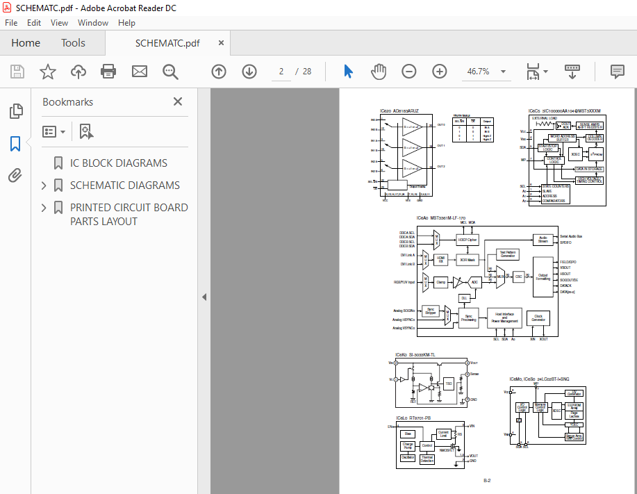
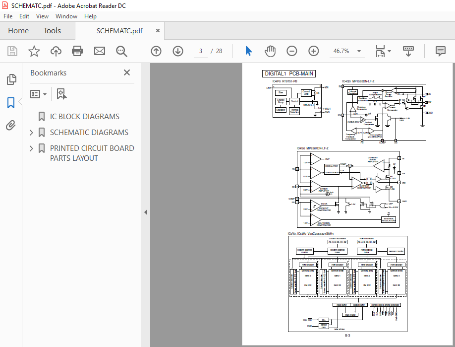
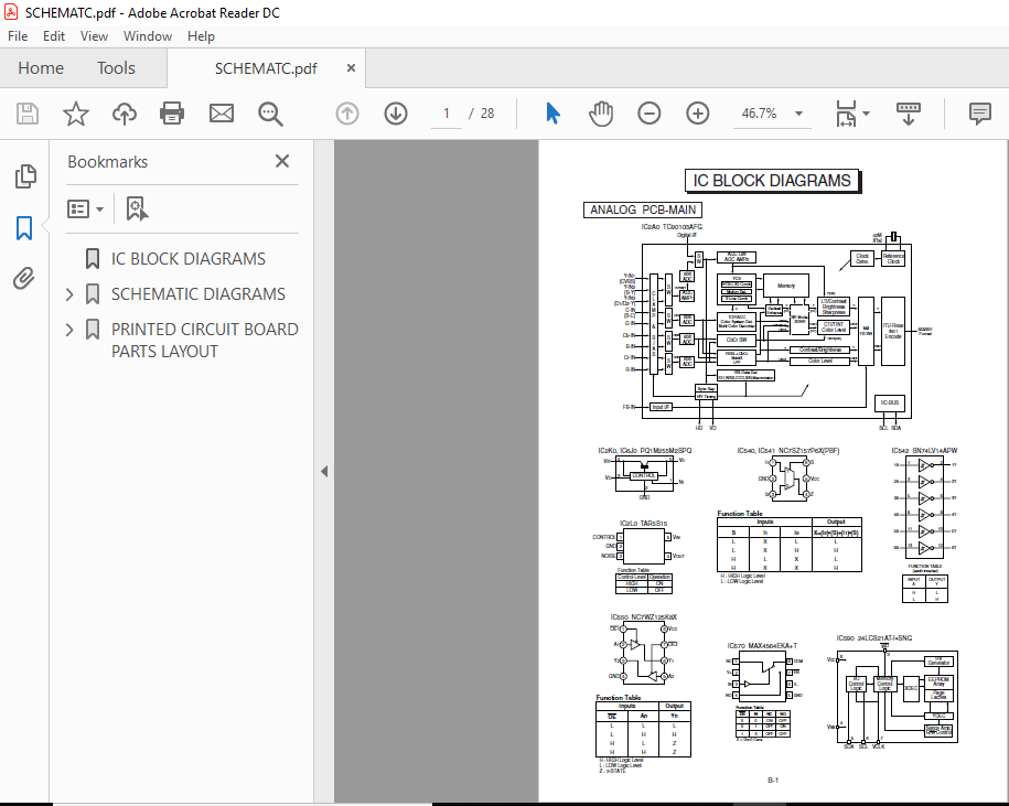
IC BLOCK DIAGRAMS
SCHEMATIC DIAGRAMS
PRINTED CIRCUIT BOARD PARTS LAYOUT
SCREENSHOT OF THE MANUAL:
VIDEO PREVIEW:

PLEASE NOTE:
⦁ This is the SAME exact manual used by your dealers to fix your vehicle.
⦁ The same can be yours in the next 2-3 mins as you will be directed to the download page immediately after paying for the manual.
⦁ Any queries / doubts regarding your purchase, please feel free to contact [email protected]


