

McCormick Tractors X4.20 X4.30 X4.30M X4.40 X4.40M X4.50M Service Manual 6638468A1 – PDF DOWNLOAD
FILE DETAILS:
McCormick Tractors X4.20 X4.30 X4.30M X4.40 X4.40M X4.50M Service Manual 6638468A1 – PDF DOWNLOAD
Language : English
Pages : 1634
Downloadable : Yes
File Type : PDF
Size: 129 MB
IMAGES PREVIEW OF THE MANUAL:
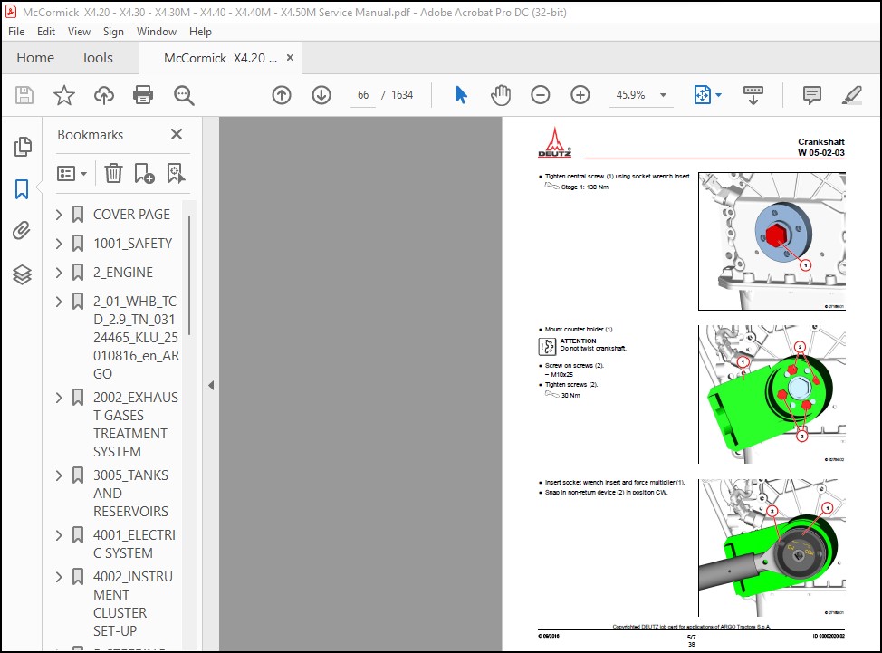
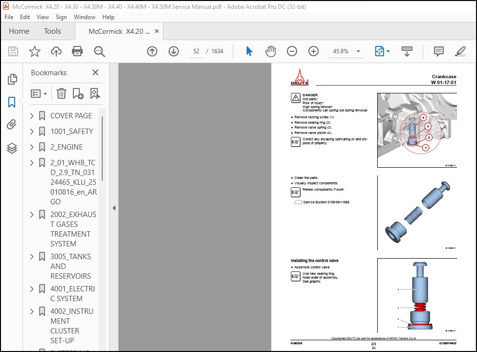
TABLE OF CONTENTS:
McCormick Tractors X4.20 X4.30 X4.30M X4.40 X4.40M X4.50M Service Manual 6638468A1 – PDF DOWNLOAD
COVER PAGE 1
Introduction 2
Liability 2
Purpose of the manual 2
Copyright 2
Table of Contents 3
1001_SAFETY 5
Safety 5
General instructions 7
Safety precautions 7
General rules 8
Danger signs 9
All markets (North America excluded) 9
Tractors with cabs 9
Tractors with footstep and safety frame 10
(North American markets) 17
Tractors with cabs 17
Tractors with footstep and safety frame 18
2_ENGINE 23
Engine 23
Technical specifications 25
General features 25
Engine Oil Selection 26
Annexes 27
2_01_WHB_TCD_2 9_TN_03124465_KLU_25010816_en_ARGO 29
General 33
Safety information / User information 34
Special tools 40
Job cards 51
W 01-17-01 Removing and installing the control valve 51
W 01-90-01 Sealing parts (Crankcase) 54
W 01-90-23 Oil measuring device 55
W 01-90-24 Oil filler neck 56
W 02-01-01 Removing and installing the lubricating oil pan (Heavy version) 57
W 05-02-03 Removing and installing the drive flange 62
W 05-90-05 Fastening parts (Pulley – drive flange) 69
W 08-00-01 Checking the compression pressure (when injectors are removed) 70
W 08-01-01 Removing and installing the cylinder head cover 76
W 09-01-01 Replacing the crankshaft sealing ring (Flywheel side) 78
W 09-02-03 Removing and installing the sealing cover 81
W 09-03-01 Removing and fitting the front cover (Fastening parts) 83
W 09-04-01 Replacing the crankshaft sealing ring (opposite side to flywheel) 87
W 09-90-63 Oil pressure control valve 90
W 15-02-01 Removing and installing the lubricating oil cooler 91
W 16-01-01 Removing and installing the oil suction pipe 93
W 16-90-32 Lubricating oil line (Auxiliary power take-off) 95
W 17-01-04 Removing and installing the high-pressure pump 96
W 19-01-01 Removing and installing the injector 104
W 20-90-16 Fuel pre-filter 110
W 20-90-17 Fuel filter 112
W 20-90-47 Fuel supply pump (electric) 114
W 21-04-01 Removing and installing the rail 116
W 21-04-03 Removing and installing the pressure relief valve (Rail) 121
W 21-04-05 Removing and installing the rail pressure sensor 124
W 21-05-05 Removing and installing the fuel line (injector, rail, high-pressure pump) 127
W 22-01-01 Removing and installing the charge air line 132
W 22-90-54 Charge air manifold 135
W 37-03-01 Removing and installing the coolant pump 136
W 37-90-05 Fastening parts (Belt pulley – coolant pump) 140
W 38-01-01 Removing and installing the thermostat 141
W 38-01-02 Checking the thermostat (when removed) 144
W 41-01-01 Removing and installing the exhaust pipe 146
W 41-05-01 Removing and installing the flutter valve 148
W 41-05-02 Removing and installing the exhaust gas recirculation module 152
W 41-05-03 Removing and installing exhaust gas recirculation valve 156
W 41-90-21 Exhaust manifold (Exhaust gas recirculation) 160
W 43-01-01 Removing and installing the exhaust gas turbocharger 161
W 43-04-01 Removing and installing the lubricating oil line 163
W 43-05-01 Removing and installing the lubricating oil return line (conduit, above) 167
W 43-05-01 Removing and installing the lubricating oil return line (conduit, below) 169
W 44-01-01 Removing and installing the belt tensioner (V-ribbed belt) 173
W 44-02-01 Removing and installing the generator (Fastening parts) 176
W 44-90-42 Generator 179
W 48-90-05 Fastening parts (Cable harness) 180
W 48-90-05 Fastening parts (Cable harness, transfer connector, crankcase) 181
W 48-90-09 Holder (Relay) 182
W 48-90-68 Cable harness 183
W 51-02-01 Removing and installing the speed sensor (Crankshaft) 184
W 51-02-03 Removing and installing the speed sensor (Camshaft) 186
W 51-08-01 Removing and installing pressure/temperature sensor (Charge air) 188
W 51-90-20 Pressure sensor installation (Lubricating oil pressure) 190
W 51-90-20 Temperature sensor (Coolant) 191
W 63-02-01 Removing and installing heating plugs 192
W 71-90-09 Holder (diesel oxidation catalytic converter 7″) 194
W 71-90-22 Clip 195
W 71-90-22 V-belt clip (System 3″) 196
W 83-90-01 Sealing parts (lubricating oil line) 197
W 83-90-05 Fastening parts (Auxiliary power take-off) 198
W 83-90-64 Blanking cover (Auxiliary power take-off) 199
2002_EXHAUST GASES TREATMENT SYSTEM 201
Exhaust gases treatment system 201
Safety 203
DOC system 204
Description 204
Boost pressure and temperature sensor 205
Exhaust gas recirculation control solenoid valve (EGR) 206
3005_TANKS AND RESERVOIRS 207
Tanks and reservoirs 207
Technical specifications 209
Safety 211
Procedures 212
Removing the fuel tank models with cab 212
Removing the fuel tank models with footstep 215
4001_ELECTRIC SYSTEM 219
Electric system (fuses, relays, wiring diagrams, connectors) 219
Technical specifications 223
Specific equipment 223
Safety 224
Symbols and names 225
Symbols 225
Key 226
Cable colour code 227
Fuses and relays (cab version) 228
Fuses and relays in the cab 229
Relay and fuse box (SFR) 229
Fuses function (SFR) 229
Relays function (SFR) 230
Relay and fuse box (SFT) 231
Fuses function (SFT) 231
Relays function (SFT) 232
Relay and fuse box (PDU) 233
Fuse function 233
Relay function 234
Fuses and relays (footstep version) 235
Fuses and relays footstep 236
Relay and fuse box (SFR) 236
Fuses function (SFR) 236
Relays function (SFR) 237
Relay and fuse box (PDU) 238
Fuse function 238
Relay function 239
Controls (cab version) 240
Cab internal controls 240
Controls on the instrument turret 240
Controls on the left-hand side of the instrument turret 240
Right controls on instrument turret 241
Cab post controls (right side) 242
Controls on cab roof 242
Controls (footstep version) 244
Controls on the instrument turret 244
Controls on the left-hand side of the instrument turret 244
Right controls on instrument turret 245
Sockets (cab and platform version) 246
Rear 7-pin socket 246
Auxiliary electric socket 247
EBS socket 248
Diagnostic sockets 249
Light units (cab version) 250
Front beams 250
Rear light units 251
Light units (footstep version) 252
Front beams 252
Rear light units 253
Topographic diagrams 255
Wiring locations (cab version) 257
Wiring locations (footstep version) 260
Component locations (cab and footstep version) 263
Description and diagrams 271
Diagram 1 – Ignition and preheating circuit 273
Diagram 2 – Recharging and ignition key circuit- cab version 281
Diagram 2 – Recharging and ignition key circuit- footstep version 287
Diagram 3 – 7-pin socket circuit – cab version 293
Diagram 3 – 7-pin socket circuit – footstep version 297
Diagram 4- Horn and electrically adjusted seat circuit- cab version 301
Diagram 4 – horn circuit – footstep version 305
Diagram 5 – Radio and courtesy light circuit – cab version 309
Diagram 6 – Windscreen wiper and rear window wiper-washer circuit – cab version 313
Diagram 7 – Four-wheel drive circuit – cab version 317
Diagram 7 – Four-wheel drive circuit – footstep version 323
Diagram 8 – auxiliary socket and cigarette lighter circuit – cab version 329
Diagram 8 – auxiliary socket circuit – footstep version 333
Diagram 9 Euro – Circuit for low-high beams, marker lights, license plate lights – cab version 337
Diagram 9 Euro – Circuit for low-high beams, marker lights, license plate lights – footstep version 343
Diagram 9 Nao – Circuit for low-high beams, marker lights, license plate lights – cab version 349
Diagram 9 Nao – Circuit for low-high beams, marker lights, license plate lights – footstep version 355
Diagram 10 – Brake and reverse lights circuit- cab version 363
Diagram 10 – Brake and reverse lights circuit- footstep version 367
Diagram 11 Euro – Circuit for turn indicators, hazard lights and rotary beacon – cab version 373
Diagram 11 Euro – Circuit for turn indicators, hazard lights and rotary beacon – footstep version 379
Diagram 11 Nao – Circuit for turn indicators, hazard lights and rotary beacon – cab version 385
Diagram 11 Nao – Circuit for turn indicators, hazard lights and rotary beacon – footstep version 391
Diagram 12 – Field lights circuit – cab version 399
Diagram 13 – Air conditioning circuit – cab version 403
Diagram 14 – Field lights circuit on bonnet- cab version 409
Diagram 14 – Circuit of field lights on bonnet- footstep version 413
Diagram 15 – Dashboard circuit – cab version 419
Diagram 15 – Dashboard circuit – footstep version 425
Diagram 16 – Trailer brake circuit 433
Diagram 17 – CAN network circuit 441
Diagram 18a – Engine circuit – vehicle side 447
Diagram 18b – Engine circuit – vehicle side 453
Diagram 18c – Engine circuit – engine side 459
Complete list of connections 465
4002_INSTRUMENT CLUSTER SET-UP 579
Instrument cluster set-up 579
General instrument cluster specifications 581
Operating menu 582
Accessories menu 583
AC4: PTO type 584
AC5: Euro or NAO market 584
AC7: Clock 584
AC8: Work hours offset 585
AC9: Service operations control 585
AC10: Configuration ECU matrix display 585
AC11: Confirmation of parameters downloading 586
5_STEERING SYSTEM 589
Steering system (operation) 589
Power steering system 591
Description 591
Technical specifications 591
Hydraulic circuit 592
ISO hydraulic diagram 593
Functional diagram 594
Power steering system operation 596
Neutral position 596
Steering position 597
Steering position (engine off) 598
5001_STEERING COLUMN AND POWER STEERING SYSTEM 599
Steering column and power steering system 599
Technical specifications 601
Tightening torques 601
Specific equipment 601
Safety 602
Procedures 603
Steering column 603
Removal 603
Splined shaft removal 605
Splined shaft re-assembly 605
Power steering system 607
Removal 607
6_TRANSMISSION 609
Transmission 613
General information 613
With mechanical reverse shuttle 613
Position of the main transmission components with mechanic reverse shuttle 614
Transmission with mechanical reverse shuttle 617
PTO clutch and transmission clutch 617
Drive axle/reverse shuttle 618
Forward speeds 618
Reverse speeds 619
Engine-transmission section with mechanical reverse shuttle 620
Gearbox 623
Description 623
Operation 624
First speed 625
Second speed 626
Third speed 627
Fourth speed 628
Speed ranges 629
Fast range 629
Slow range 630
Normal range 631
Creeper range 632
Gearbox section 634
Four-wheel drive 637
Description 637
Operation 638
Four-wheel drive engagement 638
4WD disengaged 639
Four-wheel drive section 640
Bevel gear pair and differential 643
Description 643
Operation 644
Rear differential and relative lock section 645
Side final drives 649
Description 649
Operation 649
Final drives assembly drawing 650
Rear power take-off 653
Description 653
Operation 654
Independent 1st Type 540 RPM power take-off 654
Independent 2nd Type 540/540E RPM power take-off 655
Independent 3rd Type 540/1000 RPM power take-off 656
Independent 3rd Type 540/1000 RPM power take-off NAO version 657
Synchronized 1st Type 540 RPM power take-off 658
Synchronized 2nd Type 540/540E RPM power take-off 659
Synchronized 3rd Type 540/1000 RPM power take-off 660
Synchronized 3rd Type 540/1000 RPM power take-off (NAO market) 661
Section safety lock power take-off (NAO market) 662
Operation 663
Safety lock NAO Power take-off 1000 rpm 663
Section 1st type 540 RPM power take-off 664
Section 2nd type 540/540E RPM power take-off 668
Section 3rd type 540/1000 RPM power take-off 674
Section 3rd type 540/1000 RPM power take-off (NAO markets) 680
Front axle with 4 driving wheels 687
Description 687
Limited slip differential (LSD) 688
Wheel hub 689
Front differential section 690
Wheel hub assembly section 692
Front axle with 2 driving wheels 695
Description 695
6001_ENGINE – TRANSMISSION COUPLING 697
Engine – transmission coupling 697
Technical specifications 699
Tightening torques 699
Sections and perspective views 700
Clutch (version with mechanical reverse shuttle) 700
Safety 702
Procedures 703
Clutch assembly 703
PTO clutch adjustment 703
6002_ENGINE GEARBOX ASSEMBLY 705
Disassembly of the engine-gearbox assembly 8 0
Engine gearbox assembly (Mechanical reverse shuttle) 705
Technical specifications 707
Tightening torques 707
Sections and perspective views 708
Engine-gearbox assembly (mechanical reverse shuttle) 708
Safety 711
Procedures 712
Guidelines for disassembly 712
Disassembly of the engine-gearbox assembly 712
Guidelines for re-assembly and inspections 716
Check the synchro-mesh for correct operation play 716
6006_SYNCHRONISED GEARBOX AND RANGES 719
Synchronised gearbox and ranges 719
Technical specificationss 721
Tightening torques 721
Specific equipment 722
Sections and perspective views 724
Synchronised gearbox and ranges 724
Safety 727
Procedures 728
Guidelines for disassembly 728
Removal of side cover 728
Removal of hitch 729
Removal of side final drive 731
Removal of PTO speed sensor 732
Removal of diff lock control rod and fork 732
Removal of the actuator lever of the independent / synchronised PTO 733
Removal of mechanical PTO main shaft 734
Removal of fork control rods 735
Removal of range gears 737
Removal of gearbox sub-assembly 738
Procedure to check the gearbox shafts floats 739
Removal of the upper shaft (ranges) 740
Removal of differential 741
Removal of the bevel pinion 742
Removal of range intermediate shaft 743
Removal of 4WD cover 744
Disassembly of the 4WD shaft 745
Guidelines for re-assembly and inspections 746
Inspection and re-assembly 746
6012_REAR DIFFERENTIAL 747
Rear differential 747
Technical specifications 749
Tightening torques 749
Four-spider differential, with locking system 749
Specific equipment 750
Sections and perspective views 751
Assembly drawing and main components 751
Safety 753
Procedures 754
Guidelines for disassembly, inspections and re-assembly 754
Inspections 754
How to inspect the differential housing 755
Guidelines for adjustments 756
Description of the adjustments 756
Pinion position adjustment 757
How to give the right preload to the two taper bearings that support the pinion 760
How to give the preload to the two taper bearings that support the differential 761
Play adjustment between the pinion and ring gear teeth 762
Troubleshooting for the bevel gear pair and differential 764
6018_SIDE FINAL DRIVES 765
Side final drives 765
Technical specifications 767
Tightening torques 767
Specific equipment 767
Sections and perspective views 768
Safety 770
Procedures 771
Side final drive disassembly 771
Guidelines for re-assembly 773
Re-assembly of axle shafts 773
Bearing preload adjustment 774
6019_REAR POWER TAKE-OFF 775
Rear power take-off (2 speeds with mechanical engagement) 775
Technical specifications 777
Tightening torques 777
Safety 779
Procedures 780
Guidelines for disassembly 780
Removal of PTO main shaft 780
Removal of PTO main shaft NAO markets 781
Removal of lower PTO shaft 782
Removal of lower PTO shaft NAO markets 784
Removal of the actuator lever of the independent / synchronised PTO 785
Removal of PTO speed actuator lever 786
Removal of PTO speed actuator lever NAO markets 786
Removal of PTO speed sensor 787
PTO rate sensor 787
Guidelines for re-assembly 788
Re-assembly of the lower shaft 788
Re-assembly of PTO main shaft 788
Adjustment of the PTO speed sensor 789
Specific equipment 778
6021_FRONT AXLE 791
Front axle 791
Technical specifications 793
Tightening torques 793
Differential assembly with limited slip lock 793
Side final drive assembly 794
Specific equipment 795
Safety 796
Procedures 797
Differential unit overhauling 797
Dismantling 797
Assembly 799
Bevel pinion positioning on the ring gear 800
Preload of the bearings that support the bevel pinion 801
Adjustment of the play between the teeth of the pinion and ring gear and preload of the differential bearings 802
Front final drive overhaul 803
Dismantling 803
Assembly 806
Shimming the steering angle pin 807
Preload of fork bearings 808
7_BRAKES 809
Brakes (operation) 809
Braking circuit 811
Description of operation 811
Schematic representation 812
Rear brake assembly 814
Brake pumps 815
Parking brake 816
Shut-off valve 817
4WD during braking 821
Four-wheel drive engagement with pedals (setup with footstep) 821
Four-wheel drive engagement with pedals (setup with cab) 822
Four-wheel drive engagement with parking brake (setup with footstep) 823
Four-wheel drive engagement with parking brake (setup with cab) 824
Trailer brake system 825
General description 825
Trailer brake system, type for Italy 826
Trailer brake Auxiliary, Mother Regulation type+ EEC 829
ISO hydraulic diagram braking system with trailer brakes type for Italy 832
ISO hydraulic diagram braking system with trailer brakes type Mother Regulation + EEC 833
7003_BRAKES 835
Brakes (adjustments and inspections) 835
Safety 837
Procedures 838
Rear brakes and parking brake adjustments 838
Bleeding air from the brake circuit 840
How to bleed air from the trailer brake valve (type for ITALY) 841
How to bleed air from the trailer brake valve (type MR + EEC) 841
8_HYDRAULIC COMPONENTS 843
Hydraulic components (operation) 843
Description and operation 845
General hydraulic circuit 845
sections and perspective views 847
ISO diagram (with trailer brake valve version MR + EEC) 848
ISO diagram (with trailer brake valve version MR + EEC) 849
ISO diagram (with trailer brake valve version Italy) 850
ISO diagram (with trailer brake valve version Italy) 851
Functional diagrams – Version with cab 853
Main diagram 854
Main diagram 855
4WD hydraulic circuit 856
4WD hydraulic circuit 857
Power steering system hydraulic system 858
Power steering system hydraulic system 859
Hydraulic transmission lubrication circuit 860
Hydraulic transmission lubrication circuit 861
Refrigeration hydraulic circuit 862
Refrigeration hydraulic circuit 863
PTO power clutch hydraulic circuit 864
PTO power clutch hydraulic circuit 865
Rear hitch and rear control valves hydraulic circuit 866
Rear hitch and rear control valves hydraulic circuit 867
Midmount control valves hydraulic circuit 868
Midmount valves hydraulic circuit 869
Functional diagrams – Version with FOOTSTEP 871
Main diagram 872
Main diagram 873
4WD hydraulic circuit 874
4WD hydraulic circuit 875
Power steering system hydraulic system 876
Power steering system hydraulic system 877
Hydraulic transmission lubrication circuit 878
Hydraulic transmission lubrication circuit 879
Refrigeration hydraulic circuit 880
Refrigeration hydraulic circuit 881
PTO power clutch hydraulic circuit 882
PTO power clutch hydraulic circuit 883
Rear hitch and rear control valves hydraulic circuit 884
Rear hitch and rear control valves hydraulic circuit 885
Components 887
Double hydraulic pump 888
Solenoid valve pack 889
Midmount control valve 890
Technical specifications 890
Auxiliary control valves 892
Standard single and double-acting control valve 893
Floating control valve 897
8001_HYDRAULIC COMPONENTS 901
Hydraulic components (inspections and adjustments) 901
Specific equipment 903
Troubleshooting 906
Faults of the rear hitch 906
Faults of the steering system 907
Faults of brakes 908
Faults of hydraulic trailer brake (if provided) 908
Operating pressure tests 909
Pressure tests for the low flow circuit 910
Low flow circuit’s calibration valve pressure test 910
Steering cylinder pressure test 911
4WD disengaging pressure test (Spring-on) 912
Pressure test of rear PTO clutch with mechanical reverse shuttle 913
How to check the calibration of the lubrication circuit’s pressure valve 914
How to check the calibration of the cooling circuit’s pressure valve 915
Pressure tests for the high flow circuit 916
How to check the pressure valve calibration of the rear auxiliary control valves 916
Pressure test of the rear mechanical hitch with auxiliary ram 917
Pressure test of the rear mechanical hitch without auxiliary ram 918
Test of the flow to the auxiliary control valves 919
8007_REAR HITCH 921
Rear hitch 921
GENERAL INFORMATION 923
Description 923
ISO diagram of the control valve 924
Control valve operation 924
Neutral phase 924
Loading phase 926
Discharge phase 928
TECHNICAL SPECIFICATIONS 930
Main specifications 930
Specific equipment 930
Safety 931
Procedures 932
Indications for disassembly and assembly of the hitch 932
Disassembly 932
Assembly 935
Guidelines for hitch adjustments and inspections 939
Adjustment of sensitivity control valve 940
Position control lever adjustment 941
Draft control lever adjustment 942
Inspection of the reaction pin assembly 943
Inspection of the push rod length 944
Troubleshooting 945
10_CAN LINE CONTROLLERS 947
CAN line controllers (operation) 947
Introduction 949
Electrical system 949
The CAN BUS line 949
Controllers location 951
Instrument cluster controller EC1 951
Engine controller EC6 (Deutz) 951
Diagnostic socket XS12 952
Diagnostic socket XS19 (Deutz) 952
Display of error codes 953
Safety 954
Check-control and troubleshooting 955
Conventional troubleshooting 955
Operating faults in electrical circuits 956
High resistance and open circuit 957
Grounded circuit 958
Short-circuit 959
Descriptions and diagrams 961
Diagram 17 – CAN network circuit 963
10005_ENGINE CONTROLLER 969
Engine controller (Error codes, troubleshooting, descriptions, wiring diagrams) 969
Technical specifications 973
Specific equipment 973
Safety 975
General information about the engine controller 976
CAN Bus communication 976
Alarm management priority display 976
Errors 977
Alarms displayed on the instrument cluster 977
Troubleshooting with a diagnostic code 979
Transcoding table diagnostic fault codes 979
Descriptions and diagrams 985
Diagram 1 – Ignition and preheating circuit 987
Diagram 2 – Recharging and ignition key circuit- cab version 995
Diagram 2 – Recharging and ignition key circuit- footstep version 1001
Diagram 17 – CAN network circuit 1007
Diagram 18a – Engine circuit – vehicle side 1013
Diagram 18b – Engine circuit – vehicle side 1019
Diagram 18c – Engine circuit – engine side 1025
Error codes – Settings and programming 1031
Error code (Basic checks) 1032
Error code 45 (ENGINE – A8-3) 1034
Error code 46 (ENGINE – A8-4) 1036
Error code 47 (ENGINE – A8-2) 1038
Error code 84 (ENGINE – 27F) 1040
Error code 85 (ENGINE – 4CF) 1042
Error code 88 (ENGINE – 66-2) 1044
Error code 89 (ENGINE – 66-2) 1048
Error code 96 (ENGINE – 6E-3) 1052
Error code 97 (ENGINE – 6E-4) 1056
Error code 98 (ENGINE – 6E-0) 1060
Error code 125 (ENGINE – 7FDC5) 1064
Error code 126 (ENGINE – 7FD53) 1066
Error code 171 (ENGINE – 7FBCC) 1068
Error code 179 (ENGINE – 7FBE8) 1070
Error code 198 (ENGINE – 7FBD0) 1072
Error code 291 (ENGINE – 7FE00) 1074
Error code 305 (ENGINE – 382) 1076
Error code 306 (ENGINE – 208) 1078
Error code 360 (ENGINE – 7FECE-0) 1080
Error code 361 (ENGINE – 7FECE-1) 1082
Error code 376 (ENGINE – 276-12) 1084
Error code 377 (ENGINE – 276-12) 1086
Error code 378 (ENGINE – 276-12) 1088
Error code 387 (ENGINE – 7FD5C-12) 1090
Error code 388 (ENGINE – BE-0) 1092
Error code 389 (ENGINE – BE-0) 1094
Error code 390 (ENGINE – BE-11) 1096
Error code 391 (ENGINE – BE-14) 1098
Error code 419 (ENGINE – BE-8) 1100
Error code 420 (ENGINE – BE-12) 1104
Error code 421 (ENGINE – BE-2) 1108
Error code 422 (ENGINE – BE-8) 1112
Error code 423 (ENGINE – BE-12) 1116
Error code 472 (ENGINE – 5E-3) 1120
Error code 473 (ENGINE – 5E-4) 1126
Error code 474 (ENGINE – 5E-1) 1132
Error code 475 (ENGINE – 5E-1) 1134
Error code 544 (ENGINE – 2A4) 1136
Error code 547 (ENGINE – 2D9) 1138
Error code 559 (ENGINE – 7FE77) 1140
Error code 560 (ENGINE – 7FE78) 1144
Error code 561 (ENGINE – 7FE79) 1148
Error code 565 (ENGINE – 7FC56) 1152
Error code 567 (ENGINE – 7FC5A) 1158
Error code 568 (ENGINE – 28B-5) 1164
Error code 569 (ENGINE – 28C-5) 1168
Error code 570 (ENGINE – 28D-5) 1172
Error code 571 (ENGINE – 28E-5) 1176
Error code 580 (ENGINE – 28B-3) 1180
Error code 581 (ENGINE – 28C-3) 1184
Error code 582 (ENGINE – 28D-3) 1188
Error code 583 (ENGINE – 28E-3) 1192
Error code 592 (ENGINE – 7FD5F-5) 1196
Error code 594 (ENGINE – 7FD5F-3) 1200
Error code 595 (ENGINE – 7FD5F-4) 1204
Error code 596 (ENGINE – 7FD5F-3) 1208
Error code 597 (ENGINE – 7FD5F-4) 1212
Error code 612 (ENGINE – 7FD5C-12) 1216
Error code 613 (ENGINE – 7FD5C-12) 1218
Error code 614 (ENGINE – 7FD5C-12) 1220
Error code 616 (ENGINE – 7FD5C-12) 1222
Error code 617 (ENGINE – 7FD5C-12) 1224
Error code 618 (ENGINE – 7FD5C-12) 1226
Error code 619 (ENGINE – 7FD5C-12) 1228
Error code 620 (ENGINE – 7FD5C-12) 1230
Error code 621 (ENGINE – 7FD5C-12) 1232
Error code 623 (ENGINE – 7FD5C-12) 1234
Error code 624 (ENGINE – 7FD5C-12) 1236
Error code 625 (ENGINE – 7FD5C-12) 1238
Error code 627 (ENGINE – 7FD5C-12) 1240
Error code 628 (ENGINE – 7FD5C-12) 1242
Error code 637 (ENGINE – 7FD5C-12) 1244
Error code 732 (ENGINE – 64-3) 1246
Error code 733 (ENGINE – 64-4) 1250
Error code 736 (ENGINE – 64-1) 1254
Error code 737 (ENGINE – 64-1) 1258
Error code 750 (ENGINE – 6B-3) 1262
Error code 751 (ENGINE – 6B-0) 1264
Error code 776 (ENGINE – 66-3) 1266
Error code 777 (ENGINE – 66-4) 1270
Error code 825 (ENGINE – 7FB01) 1274
Error code 826 (ENGINE – 7FCCE-2) 1278
Error code 827 (ENGINE – 7FCCE-2) 1282
Error code 828 (ENGINE – 7FCCE-12) 1286
Error code 829 (ENGINE – 7FCCE-12) 1290
Error code 830 (ENGINE – 7FCCE-14) 1294
Error code 831 (ENGINE – 7FCCE-11) 1298
Error code 832 (ENGINE – 7FCCE-11) 1302
Error code 834 (ENGINE – 7FE82-5) 1306
Error code 835 (ENGINE – 7FE82-12) 1308
Error code 836 (ENGINE – 7FE82-3) 1310
Error code 837 (ENGINE – 7FE82-4) 1312
Error code 856 (ENGINE – 7FD5D-0) 1314
Error code 857 (ENGINE – 7FD5D-0) 1318
Error code 858 (ENGINE – 7FD5D-0) 1322
Error code 859 (ENGINE – 7FD5D-0) 1326
Error code 861 (ENGINE – 7FD5D-1) 1330
Error code 862 (ENGINE – 7FD5D-0) 1334
Error code 864 (ENGINE – 7FD5D-2) 1338
Error code 876 (ENGINE – 7FCCE-7) 1342
Error code 877 (ENGINE – 9D-3) 1346
Error code 878 (ENGINE – 9D-4) 1350
Error code 935 (ENGINE – 5B-3) 1354
Error code 940 (ENGINE – 5B-4) 1356
Error code 946 (ENGINE – 437) 1358
Error code 947 (ENGINE – 438) 1364
Error code 948 (ENGINE – 7FD51) 1370
Error code 956 (ENGINE – 2A5-3) 1376
Error code 957 (ENGINE – 2A5-4) 1378
Error code 958 (ENGINE – 2A5-5) 1380
Error code 960 (ENGINE – 2A5-3) 1382
Error code 961 (ENGINE – 2A5-4) 1384
Error code 973 (ENGINE – 7FD5C-14) 1386
Error code 974 (ENGINE – 7FD5C-14) 1388
Error code 975 (ENGINE – 7FD5C-14) 1390
Error code 980 (ENGINE – 7FD1E) (cab version) 1392
Error code 980 (ENGINE – 7FD1E) (footstep version) 1394
Error code 994 (ENGINE – 69-3) 1396
Error code 995 (ENGINE – 69-4) 1400
Error code 996 (ENGINE – 69-0) 1404
Error code 997 (ENGINE – 69-0) 1408
Error code 1170 (ENGINE – 7FD5C-12) 1412
Error code 1180 (ENGINE – A8-0) 1414
Error code 1181 (ENGINE – A8-1) 1416
Error code 1223 (ENGINE – 33-5) 1418
Error code 1224 (ENGINE – 33-6) 1422
Error code 1226 (ENGINE – 33-3) 1426
Error code 1227 (ENGINE – 33-3) 1430
Error code 1228 (ENGINE – 33-4) 1434
Error code 1229 (ENGINE – 33-4) 1438
Error code 1230 (ENGINE – 33-6) 1442
Error code 1231 (ENGINE – 33-11) 1446
Error code 1232 (ENGINE – 33-4) 1450
Error code 1423 (ENGINE – 33-0) 1454
Error code 1424 (ENGINE – 33-1) 1458
Error code 1505 (ENGINE – 7FF19) 1462
Error code 1687 (ENGINE – 7FF5D) 1468
10009_INSTRUMENT CLUSTER CONTROLLER 1471
Instrument cluster controller (Descriptions, wiring diagrams, error codes, troubleshooting) 1471
Technical specifications 1473
Specific equipment 1473
Safety 1475
General information about the instrument cluster controller 1476
CAN Bus communication 1476
Changing parameters 1476
Alarm management priority display 1477
Errors 1478
Alarms displayed on the instrument cluster 1479
Descriptions and diagrams 1481
Diagram 1 – Ignition and preheating circuit 1483
Diagram 7 – Four-wheel drive circuit – cab version 1491
Diagram 7 – Four-wheel drive circuit – footstep version 1497
Diagram 15 – Dashboard circuit – cab version 1503
Diagram 15 – Dashboard circuit – footstep version 1509
Diagram 17 – CAN network circuit 1517
Error codes – Electrical diagnosis 1523
Error code (IC – 102, IC – 103 – 3/4) (cabin version) 1524
Error code (IC – 102, IC – 103 – 3/4) (footstep version) 1526
Error code (IC – 114, IC – 115 – 5/6) 1528
Error code (IC – 116, IC – 117 – 5/6) 1530
Error code (IC – 120, IC – 121 – 5/6) (cabin version) 1532
Error code (IC – 120, IC – 121 – 5/6) (footstep version) 1534
Error code (IC – 130, IC – 131 – 3/4) (cabin version) 1536
Error code (IC – 130, IC – 131 – 3/4) (footstep version) 1538
Error code (IC – 200 – 2) 1540
Error code (IC – 201 – 2) 1542
Error code (IC – 300 – 9) 1544
Error code (IC – 301 – 9) 1546
Error code (IC – 302 – 9) 1548
Error code (IC – 311 – 2) 1550
Error code (IC – 401, IC – 402, IC – 403 – 2/3/4) (cab version) 1552
Error code (IC – 401, IC – 402, IC – 403 – 2/3/4) (footstep version) 1554
Error code (IC – 406, IC – 407, IC – 408 – 2/3/4) (cab version) 1556
Error code (IC – 406, IC – 407, IC – 408 – 2/3/4) (footstep version) 1558
Error code (IC – 5072 – 7) (cabin version) 1560
Error code (IC – 5072 – 7) (footstep version) 1562
Error code (IC – 5075 – 13) 1564
Error code (IC – 5076 – 2) (cabin version) 1566
Error code (IC – 5076 – 2) (footstep version) 1568
Error code (IC – 5077 – 2) (cabin version) 1570
Error code (IC – 5077 – 2) (footstep version) 1572
Error code (IC – 5078 – 2) (cabin version) 1574
Error code (IC – 5078 – 2) (footstep version) 1576
Error code (IC – 5080, IC – 5081, IC – 5082 – 2/5/6) (cab version) 1578
Error code (IC – 5080, IC – 5081, IC – 5082 – 2/5/6) (footstep version) 1580
Error code (IC – 5094 – 8) (cabin version) 1582
Error code (IC – 5094 – 8) (footstep version) 1584
Error code (IC – 5100 – 12) 1586
10010_CONTROLLER PROGRAMMING 1587
Controller programming (Argo Tractors DIAG4) 1587
Technical specifications 1589
Specific equipment 1589
INTRODUCTION 1591
DIAG4 connection to the tractor 1591
VCI connections and settings 1593
Connection to the tractor 1610
Model selection 1611
Errors 1615
Set-ups 1616
How to download the software 1617
Procedures 1618
Report 1618
Flight Recorder 1619
DOWNLOADS 1623
Software download (e g instrument cluster controller) 1623
DESCRIPTION:
McCormick Tractors X4.20 X4.30 X4.30M X4.40 X4.40M X4.50M Service Manual 6638468A1 – PDF DOWNLOAD
INTRODUCTION:
This manual refers to the X4.20 – X4.30 – X4.30m – X4.40 – X4.40m – X4.50m tractors produced by
McCormick and is divided into numbered sections, according to their subjects.
– The subjects described are listed in the general index and appear in more detail in the specific index of
the section in question.
– The print number of the manual appears at the bottom left of each page and the date of the relative
edition/update is printed at the bottom right.
– Pages where future updates are made will have the same printed number but the new date of issue.
These pages will be supplied by a reprint of the duly updated index.
– The information in this manual was up to date on the date printed on the page. Since McCormick
constantly updates its range of products, some of the information could no longer be up to date
following modifications made for technical or commercial reasons, or to adapt the machines to the laws
in force in the various countries of use.
Consult our Dealers and Assistance Centres if discrepancies are found.
VIDEO PREVIEW OF THE MANUAL:
PLEASE NOTE:
- This is the same manual used by the dealers to diagnose and troubleshoot your vehicle
- You will be directed to the download page as soon as the purchase is completed. The whole payment and downloading process will take anywhere between 2-5 minutes
- Need any other service / repair / parts manual, please feel free to contact [email protected] . We still have 50,000 manuals unlisted
S.V


