

Massey Ferguson MF6700S Series Tractors Technician Service Book Service Manual – PDF DOWNLOAD
FILE DETAILS:
Massey Ferguson MF6700S Series Tractors Technician Service Book Service Manual – PDF DOWNLOAD
Format: PDF
Language: English
Brand: Massey Ferguson
VIDEO PREVIEW OF THE MANUAL:

IMAGES PREVIEW OF THE MANUAL:

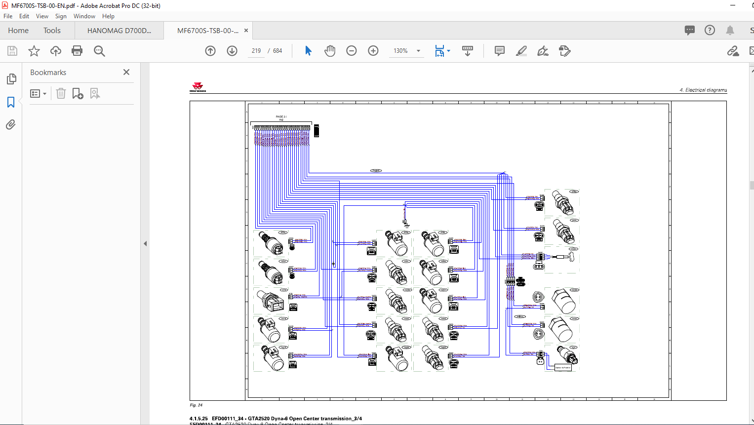
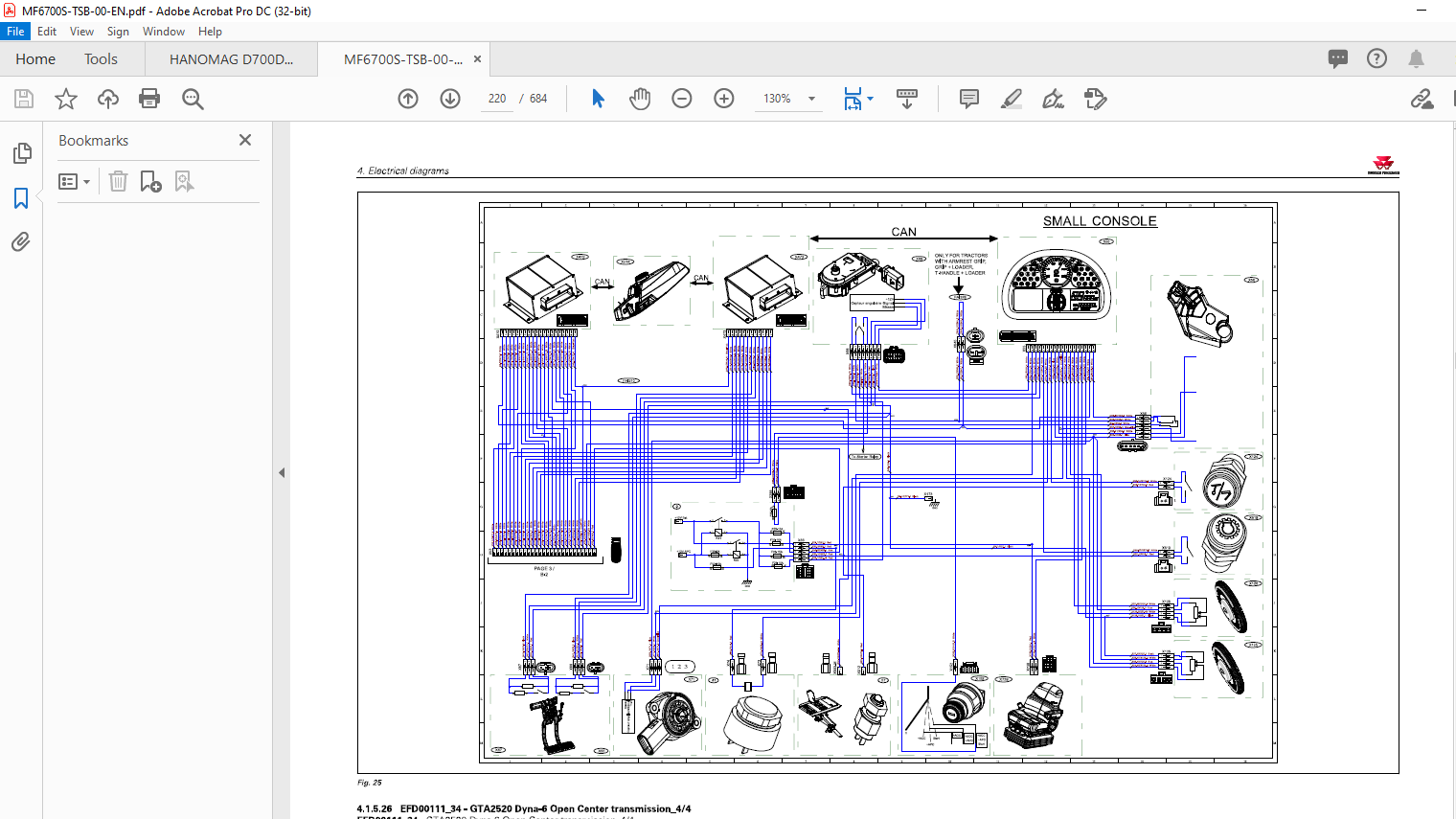
TABLE OF CONTENTS:
Massey Ferguson MF6700S Series Tractors Technician Service Book Service Manual – PDF DOWNLOAD
1 General 1-1
1 1 General specifications 1-3
1 1 1 tractors MF 6700 SDyna-4 1-3
1 1 2 Tractors MF 67 00 SDyna-6 1-1 1
1 1 3 MF 67 00 S Dyna-VT tractors 1-20
1 2 Forward speeds 1-30
1 2 1 Forward speed with Dyna-4 4 0k ph transmission and 18 4R38 tires 1-30
1 2 2 Forward speed with Dyna-4 4 0k ph transmission and 20 8R38 tires 1-30
1 2 3 Forward speed with Dyna-6 4 0k ph ECO transmission and 20 8R38 tires 1-32
1 2 4 Forward speed with Dyna-6 5 0k ph transmission and 20 8R38 tires 1-33
1 2 5 Forward speed for all models with transmission in Dyna-VT mode 1-3 5
1 3 Dimensions and weights 1-37
1 3 1 Dimensions and weights 1-37
1 4 Attachment points 1-41
1 4 1 Attachment points: MF 67 1 2 S / MF 671 3 S / MF 671 4 S Dyna-4/ Dyna-6 models
without front linkage 1-4 1
1 4 2 Attachment points: MF 67 1 2 S / MF 671 3 S / MF 671 4 S Dyna-4/ Dyna-6 models
with front linkage 1-4 3
1 4 3 Attachment points: MF 67 1 5 S / MF 67 1 6 S / MF 67 18 S Dyna-4/ Dyna-6 models
without front linkage 1-4 5
1 4 4 Attachment points: MF 67 1 5 S/ MF 67 1 6 S / MF 67 18 S Dyna-4/ Dyna-6 models
with front linkage 1-47
1 4 5 Attachment points: MF 67 1 3 S / MF 67 1 4 S / MF 67 1 5 S / MF 67 1 6 S / MF 67 18 S
Dyna-VT models witho ut front linkage: 1-49
1 4 6 Attachment points: MF 671 3 S / MF 671 4 S / MF 671 5 S / MF 67 1 6 S / MF 67 18 S
Dyna-VT models with front linkage 1-5 1
1 5 Capacities 1-53
1 5 1 Capacities 1-5 3
1 6 Tightening torques, retaining compounds and sealing products 1-55
1 6 1 Retaining compounds and sealing products 1-5 5
1 6 2 Tightening torques for screws and nuts 1-5 6
1 6 3 Tightening torques for h ydraulic unions 1-6 0
1 7 Units of measurement 1-64
1 7 1 Conversion table 1-64
2 Error codes 2-1
2 1 Error codes 2-3
2 1 1 General table of faults 2-3
2 1 2 Indicator light panel 2-6
2 1 3 Indication of faults 2-1 3
2 1 4 Description of error code format 2-1 6
2 1 5 Instrument panel error codes Dyna-VT 2-17
2 1 6 Instrument panel error codes Dyna-4/ Dyna-6 2-18
2 1 7 AGCO Power Tier 3/Stage IIIA engine and Tier 4F/Stage IV SCR Technolog y
engine error codes 2-19
2 1 8 Dyna-VT transmission error codes 2-3 5
2 1 9 Transmission error codes Dyna-4/ Dyna-6 2-38
2 1 1 0 Front axle error codes Dyna-VT 2-4 0
2 1 1 1 Front axle error codes for Dyna-4/ Dyna-6 2-4 1
Technician Service Book – series tractors MF 6700 S
ACT002565A
Table of contents
2 1 12 Rear power take-off error codes Dyna-VT 2-4 1
2 1 1 3 Power take-off error codes Dyna-4/Dyna-6 2-4 3
2 1 1 4 Error codes for the high-pressure braking 2-4 4
2 1 1 5 Rear linkage error codes 2-4 4
2 1 16 Front power lift error codes 2-4 6
2 1 17 Armrest error codes 2-4 6
2 1 1 8 H ydraulic valve error codes 2-47
2 1 19 Air conditioning error codes 2-49
2 1 20 Error codes of the ke ypad in the pillar 2-5 0
2 1 21 Suspended cab error codes 2-5 1
3 Fuse box 3-1
3 1 Fuse box 3-3
3 1 1 Description of the main fuse box 3-3
3 1 2 Description of the secondar y fuse box (depending on model) 3-21
3 1 3 Description of additional fuses specific to the panoramic cab 3-25
3 1 4 Batter y isolator 3-27
4 Electrical diagrams 4-1
4 1 Electrical diagrams 4-7
4 1 1 Identification of electrical diagrams 4-7
4 1 2 Identification of electrical connectors from X1 to X5 00 4-9
4 1 3 Identification of electrical connectors from X5 01 to X1 000 4-21
4 1 4 Identification table for cable colors 4-3 0
4 1 5 Electrical diagrams 4-33
4 1 5 1 EFD00000_ 1 6 – Batter y 1 2 V power supply points 4-3 3
4 1 5 2 EFD00000_ 17 – Batter y earth points 4-3 4
4 1 5 3 EFD001 00_ 17 – 4-wheel dri ve Dyna-VT 4-3 6
4 1 5 4 EFD001 00_ 18 – 4-wheel dri ve Dyna-6 4-37
4 1 5 5 EFD001 00_ 19 – 4-wheel dri ve Dyna-4 4-37
4 1 5 6 EFD001 01_ 17 – Differential lock Dyna-VT 4-38
4 1 5 7 EFD001 01_ 1 8 – Differential lock Dyna-6 4-39
4 1 5 8 EFD001 01 _ 19 – Differential lock Dyna-4 4-4 0
4 1 5 9 EFD001 06_28 -rear power take-off Dyna-VT 4-4 1
4 1 5 1 0 EFD001 06_3 2 – G PA 20 mechanical-control rear power take-off Dyna-6 4-4 2
4 1 5 1 1 EFD001 06_33 – G PA 20 electroh ydraulic-control rear power take-off
Dyna-6 4-4 3
4 1 5 1 2 EFD001 06_3 4 – G PA 20 mechanical-control rear power take-off Dyna-4 4-4 4
4 1 5 1 3 EFD001 06_3 5 – G PA 20 electroh ydra ulic-control rear power takeoff
Dyna-4 4-4 5
4 1 5 1 4 EFD001 07 _ 1 1 -front power take-off Dyna-VT 4-4 6
4 1 5 1 5 EFD001 07 12- front power take-off Dyna-6 4-47
4 1 5 1 6 EFD001 07 1 3 -front power take-off Dyna-4 4-4 8
4 1 5 17 EFD001 1 1_ 3 1 -transmission Dyna-VT_ 1/ 2 4-49
4 1 5 18 EFD001 1 1_ 3 1 -transmission Dyna-VT _2/ 2 4 -5 0
4 1 5 19 EFD001 1 1_ 33 -GTA25 20 transmission Dyna-6 Load Sensing_ 1 /4 4-5 1
4 1 5 20 EFD001 1 1 _33 – GTA 25 20 transmission Dyna-6 Load Sensing _2/4 4-5 2
4 1 5 21 EFD001 1 1 _33 – GTA 25 20 transmission Dyna-6 Load Sensing_3 /4 4-5 3
4 1 5 22 EFD001 1 1 _33 – GTA 25 20 transmission Dyna-6 Load Sensing _ 4 /4 4-5 4
4 1 5 23 EFD001 1 1 _3 4 – GTA 25 20 Dyna-6 Open Center transmission _ 1/ 4 4-5 5
4 1 5 24 EFD001 1 1 _3 4 – GTA 25 20 Dyna-6 Open Center transmission _2/ 4 4-5 6
4 1 5 25 EFD001 1 1 _3 4 – GTA 25 20 Dyna-6 Open Center transmission _3/ 4 4-5 7
4 1 5 26 EFD001 1 1 _3 4 – GTA 25 20 Dyna-6 Open Center transmission _ 4/ 4 4-5 8
4 1 5 27 EFD001 1 1 _3 5 – GTA 25 20 transmission Dyna-4 Load Sensing _ 1/ 2 4-5 9
4 1 5 28 EFD001 1 1_ 3 5 -GTA25 20 transmission Dyna-4 Load Sensing_2/ 2 4-60
4 1 5 29 EFD001 1 1 _36 – GTA 25 20 Dyna-4 Open Center transmission _ 1/ 2 4-6 1
4 1 5 3 0 EFD001 1 1 _36 – GTA 25 20 Dyna-4 Open Center transmission _2/ 2 4-62
4 1 5 3 1 EFD001 1 3_7 -Cigarette lighter 4-63
Technician Service Book- series tractors MF 6700 S
ACT002565A
Table of contents
4 1 5 32 EFD001 1 4 _3 0- Radio 4-64
4 1 5 33 EFD001 1 6_ 12- Suspended cab 4-65
4 1 5 3 4 EFD001 17 _28 -Additional heater 4-66
4 1 5 3 5 EFD001 17 39 -Automatic air conditioning 4-67
4 1 5 36 EFD001 17 4 0- Manual air conditioning for standard roof 4-68
4 1 5 37 EFD001 17 4 1 – Manual air conditioning for high-visibilit y roof 4-69
4 1 5 38 EFD001 18_9 – DOT Matrix 4-70
4 1 5 39 EFD001 19_ 1 0- Rear windscreen wiper 4-71
4 1 5 4 0 EFD001 19 _ 1 1 -Rear windscreen wiper for tractors with panoramic cab 4-72
4 1 5 4 1 EFD00120_ 12- Front windscreen wiper 4-73
4 1 5 4 2 EFD001 21 _9 -parking brake Dyna-VT 4-74
4 1 5 4 3 EFD00121 _ 1 0- parking brake Dyna-6 4-75
4 1 5 4 4 EFD001 21 _ 1 1 -parking brake Dyna-4 4-76
4 1 5 4 5 EFD001 22_8 -fuel gage Dyna-VT 4-77
4 1 5 4 6 EFD001 22_9 – Dyna-4/ fuel gage Dyna-6 4-78
4 1 5 47 EFD001 23 -C 3 000 4-79
4 1 5 48 EFD001 23_24 – Datatronic CC D 4-80
4 1 5 49 EFD001 23_25 -lsobus 4-81
4 1 5 5 0 EFD001 23_3 0 -Auto-Guide ™ 4-82
4 1 5 5 1 EFD00125 _ 1 0- Cab light 4-83
4 1 5 5 2 EFD001 26_ 1 1 – Extreme cold weather heating with automatic air
conditioning 4-84
4 1 5 5 3 EFD001 26_ 1 2 – Extreme cold weather heating with manual air
conditioning for tractors with standard roof 4-85
4 1 5 5 4 EFD001 26_ 1 3 – Extreme cold weather heating with manual air
conditioning for tractors with high-visibilit y roof 4-86
4 1 5 5 5 EFD001 27 _8 – Left-hand pillar 1 2 V socket 4-87
4 1 5 5 6 EFD001 28_ 17 – E A M E /ISO cab power socket 4-88
4 1 5 57 EFD001 28_ 18 -NNSA E cab power socket 4-89
4 1 5 5 8 EFD001 28_20 – E A M E /ISO cab power socket _ 1/ 2 4-9 0
4 1 5 5 9 EFD001 28_20 – E A M E /ISO cab power socket _2/ 2 4-9 1
4 1 5 6 0 EFD001 28_21 -NNSA E cab power socket _ 1/ 2 4-9 2
4 1 5 6 1 EFD001 28_21 – NNSAE cab power socket _2/ 2 4-9 3
4 1 5 62 EFD001 29_ 1 2 – Diagnostics connector _ 1/ 2 4-9 4
4 1 5 63 EFD001 29_ 1 2 – Diagnostics connector _2/ 2 4-9 5
4 1 5 6 4 EFD001 29 _ 1 3 – Diagnostics connector _ 1/ 2 with cab harnesses
ACW 039 1 62 and ACW 039 1 67 4-97
4 1 5 65 EFD001 29 _ 1 3 – Diagnostics connector _2/ 2 with cab harnesses
ACW 039 1 62 and ACW 039 1 67 4-97
4 1 5 66 EFD001 3 0_ 5 -radar Dyna-VT 4-99
4 1 5 67 EFD001 3 0_6 – Dyna-6 and radar Dyna-4 4-99
4 1 5 68 EFD001 3 1 _3 4 – CAN network Dyna-VT (tractorU/ 5 with Tier 4F/Stage
IV SCR Technolog y engine and cab harness 499 024 3 4-1 00
4 1 5 69 EFD001 3 1 _3 4 – CAN network Dyna-VT (hitch) _2/ 5 with Tier 4F/Stage I V
SCR Technolog y engine and cab harness 499 024 3 4-1 01
4 1 5 70 EFD001 3 1 _3 4 – CAN network Dyna-VT (engine) _3/ 5 with Tier 4F/Stage
IV SCR Technolog y engine and cab harness 499 024 3 4-1 02
4 1 5 71 EFD001 3 1 _3 4 – CAN network Dyna-VT (isobus) _ 4/ 5 with Tier 4F/Stage
IV SCR Technolog y engine and cab harness 499 024 3 4-1 03
4 1 5 72 EFD001 3 1 _3 4 – CAN network Dyna-VT (AGCO Powerl _ 5 / 5 with Tier 4F/
Stage I V SCR Technolog y engine and cab harness 499 024 3 4-1 04
4 1 5 73 EFD001 3 1 _3 5 – CAN network Dyna-6 (tractor) _ 1/7 with Tier 4F/Stage I V
SCR Technolog y engine and cab harnesses ACW 005780-ACW 005784-4 39 26 4 2 4-1 05
4 1 5 74 EFD001 3 1 _3 5 -CAN network Dyna-6 (enginel _2/7 with Tier 4F/Stage I V
SCR Technolog y engine and cab harnesses ACW 005780-ACW 005784-4 39 26 4 2 4-1 06
4 1 5 75 EFD001 3 1 _3 5 – CAN network Dyna-6 (hitchl _3/7 with Tier 4F/Stage I V
SCR Technolog y engine and cab harnesses ACW 005780-ACW 005784-4 39 26 4 2 4-1 07
Technician Service Book – series tractors MF 6700 S
ACT002565A
Table of contents
4 1 5 76 EFD001 3 1 _3 5 – CAN network Dyna-6 (isobus) _ 4/7 with Tier 4F/Stage I V
SCR Technolog y engine and cab harnesses ACW 005780-ACW 005784-4 39 26 4 2 4-1 08
4 1 5 77 EFD001 3 1 _3 5 – CAN network Dyna-6 (tractor) _ 5/7 with Tier 4F/Stage I V
SCR Technolog y engine and cab harnesses ACW 005780-ACW 005784-4 39 26 4 2 4-1 09
4 1 5 78 EFD001 3 1 _3 5 – CAN network Dyna-6 (engine) _ 6/7 with Tier 4F/Stage I V
SCR Technolog y engine and cab harnesses ACW 005780-ACW 005784-4 39 26 4 2 4-1 1 0
4 1 5 79 EFD001 3 1 _3 5 – CAN network Dyna-6 (AGCO Power) _7/7 with Tier 4F/
Stage I V SCR Technolog y engine and cab harnesses ACW 005780-
ACW 005784-4 39 26 4 2 4-1 1 1
4 1 5 80 EFD001 3 1 _36 – CAN network Dyna-4 (tractorU/ 3 with Tier 4F/Stage I V
SCR Technolog y engine and cab harnesses ACW 017847-ACW 0223 03-
ACW 021 4 9 2-4 39 1826 4-1 1 2
4 1 5 81 EFD001 3 1 _3 6 – CAN network Dyna-4 (engine) _2/ 3 with Tier 4F/Stage I V
SCR Technolog y engine and cab harnesses ACW 017847-ACW 0223 03-
ACW 021 4 9 2-4 39 1826 4-1 1 3
4 1 5 82 EFD001 3 1 _36 – CAN network Dyna-4 AGCO Power _3/ 3 with Tier 4F/
Stage I V SCR Technolog y engine and cab harnesses ACW 017847-ACW 0223 03-
ACW 021 4 9 2-4 39 1826 4-1 1 4
4 1 5 83 EFD001 3 1 _39 – CAN network Dyna-6 (tractorU/7 with Tier 4F/Stage I V
SCR Technolog y engine and cab harness ACW 039 1 67 4-1 1 5
4 1 5 84 EFD001 3 1 _39 – CAN network Dyna-6 (enginel _2/7 with Tier 4F/Stage I V
SCR Technolog y engine and cab harness ACW 039 1 67 4-1 1 6
4 1 5 85 EFD001 3 1 _39 – CAN network Dyna-6 (hitchl _3/7 with Tier 4F/Stage I V
SCR Technolog y engine and cab harness ACW 039 1 67 4-1 17
4 1 5 86 EFD001 3 1 _39 – CAN network Dyna-6 (isobus) _ 4/7 with Tier 4F/Stage I V
SCR Technolog y engine and cab harness ACW 039 1 67 4-1 18
4 1 5 87 EFD001 3 1 _39 – CAN network Dyna-6 (tractorl _ 5/7 with Tier 4F/Stage I V
SCR Technolog y engine and cab harness ACW 039 1 67 4-1 19
4 1 5 88 EFD001 3 1 _39 – CAN network Dyna-6 (engine) _6/7 with Tier 4F/Stage I V
SCR Technolog y engine and cab harness ACW 039 1 67 4-1 20
4 1 5 89 EFD001 3 1 _39 – CAN network Dyna-6 AGCO Power _7/7 with Tier 4F/
Stage I V SCR Technolog y engine and cab harness ACW 039 1 67 4-1 21
4 1 5 9 0 EFD001 3 1 _ 4 0 – CAN network Dyna-VT (tractorl _ 1/ 5 with Tier 4F/Stage
I V SCR Technolog y engine and cab harness ACW 039 1 62 4 -1 22
4 1 5 9 1 EFD001 3 1 _ 4 0 – CAN network Dyna-VT (hitch) _2/ 5 with Tier 4F/Stage I V
SCR Technolog y engine and cab harness ACW 039 1 62 4-1 23
4 1 5 92 EFD001 3 1 _ 4 0- CAN network Dyna-VT (engine) _3/ 5 with Tier 4F/Stage
I V SCR Technolog y engine and cab harness ACW 039 1 62 4 -1 24
4 1 5 9 3 EFD001 3 1 _ 4 0 – CAN network Dyna-VT (isob us) _ 4/ 5 with Tier 4F/Stage
I V SCR Technolog y engine and cab harness ACW 039 1 62 4 -1 25
4 1 5 9 4 EFD001 3 1 _ 4 0 – CAN network Dyna-VT AGCO Power _ 5 / 5 with Tier 4F/
Stage I V SCR Technolog y engine and cab harness ACW 039 1 62 4-1 26
4 1 5 9 5 EFD001 3 2_7 – Electric rear-view mirrors 4-1 27
4 1 5 9 6 EFD001 33_7 – Pneumatic seat 4-1 28
4 1 5 97 EFD001 3 5 _ 1 1 – Ventilation for tractors with standard roof 4-1 29
4 1 5 98 EFD001 3 5 _ 12- Ventilation for tractors with high-visibilit y roof 4-1 3 0
4 1 5 99 EFD001 3 6_ 5 9 – EAM E direction indicators and hazard warning lights –
standard roof 4-1 3 1
4 1 5 1 00 EFD001 3 6_60 -NA direction indicators and ha zard warning lights 4-1 3 2
4 1 5 1 01 EFD001 3 6_6 1 – E A M E direction indicators and hazard warning lights –
high-visibilit y roof 4-1 3 3
4 1 5 1 02 EFD001 37 _23 -Number plate lighting (except Ital y) 4 -1 3 4
4 1 5 1 03 EFD001 37 _24 – Italian number plate lighting 4-1 3 5
4 1 5 1 04 EFD00138_3 5 -NA side lights 4-1 3 6
4 1 5 1 05 EFD001 38_ 4 2- EAME side lights 4-1 37
4 1 5 1 06 EFD001 39 _8 -Reversing light Dyna-VT 4-1 38
4 1 5 1 07 EFD001 39 _9 – Reversing light Dyna-6 4-1 39
4 1 5 1 08 EFD001 39_ 12- Reversing light Dyna-4 4-1 4 0
Technician Service Book- series tractors MF 6700 S
ACT002565A
Table of contents
4 1 5 1 09 EFD001 4 0_ 4 8 – High beam lamps and low beam lamps on grille and
hand rails 4-1 4 1
4 1 5 1 1 0 EFD001 4 0_ 49 – High beam lamps and low beam lamps on hand rails 4-1 4 2
4 1 5 1 1 1 EFD001 4 0_ 5 0 – High beam lamps and low beam lamps on grille 4-1 4 3
4 1 5 1 1 2 EFD001 4 0_ 5 1 – High beam lamps and low beam lamps on grille 4-1 4 4
4 1 5 1 1 3 EFD001 4 1_ 77 -Work lights for tractors with panoramic cab 4-1 4 5
4 1 5 1 1 4 EFD001 4 1_ 78 – Work lights + high beam lamps on hand rails for
tractors with panoramic cab 4-1 4 6
4 1 5 1 1 5 EFD001 4 1 _9 5 – EAM E work lights 4-1 47
4 1 5 1 1 6 EFD001 4 1 _ 96 -NA work lights 4-1 48
4 1 5 1 17 EFD001 4 1_ 97 -Work lights 4-1 49
4 1 5 1 18 EFD001 4 2_ 12 – Brake lights Dyna-VT 4-1 5 0
4 1 5 1 19 EFD001 4 2_ 1 3 – Brake lights Dyna-6 4-1 5 1
4 1 5 1 20 EFD001 4 2_ 1 4 – Brake lights Dyna-4 4-1 5 2
4 1 5 1 21 EFD001 4 3 _27 -Rotar y beacon 4-1 5 3
4 1 5 1 22 EFD001 4 4 _8 -Control module 4-1 5 4
4 1 5 1 23 EFD001 4 5 _ 1 3 – NA trailer connector 4-1 5 5
4 1 5 1 24 EFD001 4 5 _ 1 4 – E A M E trailer connector 4-1 5 6
4 1 5 1 25 EFD001 4 6_9 -Automatic air conditioning back-lighting 4-1 5 7
4 1 5 126 EFD001 4 6_ 1 0- Manual air conditioning back-lighting 4-1 5 8
4 1 5 1 27 EFD001 4 8_ 1 3 -Audible alarm 4-1 5 9
4 1 5 1 28 EFD001 4 9 _ 1 6 – Batter y charge + start-up Tier 4F/Stage I V SCR
Technolog y engine 4-1 6 0
4 1 5 129 EFD001 5 0_ 1 0- Air filter vacuum sensor 4-1 6 1
4 1 5 1 3 0 EFD001 5 1 _33 – E E M unit power s uppl y AGCO Power ( 49 AWF engine)
4-1 62
4 1 5 1 3 1 EFD001 5 1 _3 4 – AGCO Power engine electronic injection for Efficient
and tractor versions Excl usi ve ( 49 AWF engine) 4-1 63
4 1 5 1 32 EFD001 5 1 _ 3 5 – AGCO Power engine electronic injection for tractor
versions Essential ( 49 AWF engine) 4-1 6 4
4 1 5 1 3 3 EFD001 5 2_ 19 -Suspended front axle (for MF 67 00 S models) 4-1 65
4 1 5 1 3 4 EFD001 5 3_20 – Preheating power s upply AGCO Power (66/74 CW-3
and 49AWF engine) 4-1 66
4 1 5 1 3 5 EFD001 5 4 _6 -Fuel preheater 4-1 67
4 1 5 1 3 6 EFD001 5 7 _6 – Vistronic Tier 4F/Stage I V SCR Technolog y engine 4-1 68
4 1 5 1 37 EFD001 5 9 _ 18 – H ydraulic spool valves Dyna-VT 4-1 69
4 1 5 1 38 EFD001 5 9 _ 19 – H ydraulic spool valves Dyna-6 4-17 0
4 1 5 139 EFD001 6 0_29 -Rear linkage and Dual Control Dyna-VT 4-17 1
4 1 5 1 4 0 EFD001 6 0_3 0 – G PA 20 and G PA 4 0 Dual Control and rear linkage
Dyna-6_ 1 / 2 4-172
4 1 5 1 4 1 EFD001 6 0_3 0 – G PA 20 and G PA 4 0 Dual Control and rear linkage
Dyna-6_2/ 2 4-173
4 1 5 1 4 2 EFD001 6 0_3 1 – Dyna-6 Open Center G PA 20 Dual Control and rear
linkage 4-17 4
4 1 5 1 4 3 EFD001 6 0_32 – Dyna-4 Load Sensing G PA20 Dual Control and rear
linkage 4-17 5
4 1 5 1 4 4 EFD001 6 0_33 – Dyna-4 Open Center G PA 20 Dual Control and rear
linkage 4-176
4 1 5 1 4 5 EFD001 6 1 1 3 -Front linkage 4-177
4 1 5 1 4 6 EFD001 62_ 1 1 – Dual Control linkage and trailed implements (TIC)
Dyna-VT 4-178
4 1 5 1 47 EFD001 62_ 1 2 – Dual Control linkage and trailed implements (TIC)
Dyna-6 4-179
4 1 5 1 4 8 EFD001 66_2 -Side windscreen wiper for tractors with panoramic cab 4-18 0
4 1 5 1 49 EFD001 67 _2 – Triflash for tractors with panoramic cab 4-18 1
4 1 5 1 5 0 EFD001 68_2 -Rear fog light for tractors with panoramic cab 4-182
4 1 5 1 5 1 EFD001 69 _ 18 -Controller power s upply Dyna-VT _ 1/ 5 4-183
4 1 5 1 5 2 EFD00169_ 18 -Controller power s upply Dyna-VT _2/ 5 4-184
Technician Service Book – series tractors MF 6700 S
ACT002565A
Table of contents
4 1 5 1 5 3 EFD001 69 _ 18 – Controller power s uppl y Dyna-VT _3/ 5 4-185
4 1 5 1 5 4 EFD001 69 _ 18 – Controller power s uppl y Dyna-VT _ 4/ 5 4-186
4 1 5 1 5 5 EFD001 69 _ 18 – Controller power s upply Dyna-VT _ 5 / 5 4-187
4 1 5 1 5 6 EFD00169_ 19 – Controller power s uppl y Dyna-6 – Transmission 4-188
4 1 5 1 57 EFD00169_ 19 – Controller power s uppl y Dyna-6 -linkage 4-189
4 1 5 1 5 8 EFD00169_ 1 9 – Controller power s upply Dyna-6 -s uspended front axle
(T E CU) 4-19 0
4 1 5 1 5 9 EFD00169_ 1 9 – Controller power s uppl y Dyna-6 -Instrument panel 4-19 1
4 1 5 1 6 0 EFD001 69 _ 19 – Controller power s upply Dyna-6 -Suspended cab 4-19 2
4 1 5 1 6 1 EFD001 69 _20 – Controller power s uppl y Dyna-4 _ 1/ 4 4-19 3
4 1 5 1 62 EFD001 69 _20 – Controller power s uppl y Dyna-4 _2/ 4 4-19 4
4 1 5 1 63 EFD001 69 _20 – Controller power s uppl y Dyna-4 _3/ 4 4-19 5
4 1 5 1 6 4 EFD001 69 _20 – Controller power s uppl y Dyna-4 _ 4/ 4 4-19 6
4 1 5 1 6 5 EFD00170_3 – High-pressure braking 4-197
4 1 5 1 66 EFD00172_6 -Front accessor y connection socket _ 1/ 2 4-198
4 1 5 1 67 EFD00172_6 -Front accessor y connection socket _2/ 2 4-199
4 1 5 1 68 EFD00173_7 – Water in fuel sensor of the Tier 4F/Stage IV SCR
Technolog y engine 4-200
4 1 5 1 69 EFD00174 _ 1 2 -air brake Dyna-VT_ 1/ 2 4-201
4 1 5 170 EFD00174 _ 1 2 -air brake Dyna-VT _2/ 2 4-202
4 1 5 171 EFD00174 _ 1 4 – G PA 20 and G PA 5 0 air brake Dyna-6 4-203
4 1 5 172 EFD00174 _ 1 5 – G PA 20 and G PA 5 0 air brake Dyna-4 4-204
4 1 5 173 EFD00175 – Tier 4f/Stage I V AGCO Power engine _ 1/ 3 4-205
4 1 5 174 EFD00175 – Tier 4f/Stage I V AGCO Power engine _2/ 3 4-206
4 1 5 175 EFD00175 – Tier 4f/Stage I V AGCO Power engine _3/ 3 4-207
4 1 5 176 EFD00175 _9 -SCR Technolog y 4-208
4 1 5 177 EFD00176 – LoaderALO 4-209
4 1 5 178 EFD00176_ 1 4 -front set Dyna-6 4-21 0
4 1 5 179 EFD00176_ 1 5 – A LO loader Dyna-6 4-21 1
4 1 5 180 EFD00176_ 1 6 -front set Dyna-VT 4-21 2
4 1 5 181 EFD00176_ 17 – A LO mechanical loader Dyna-4 4-21 3
4 1 5 182 EFD00178_ 5 -Steering SpeedSteer 4-21 4
4 1 5 183 EFD00183_2 -Implement attachment without lsobus 4-21 5
4 1 5 184 EFD00184 _3 -AgCommand ™ 4-21 6
5 Harnesses 5-1
5 1 Harnesses 5-5
5 1 1 Identification of harnesses 5-5
5 1 2 Identification table for cable colors 5-8
5 1 3 Harnesses 5-1 1
5 1 3 1 FAl 200 – Engine harness cab -ACW 03 499 4 0_ 1 / 2 5-1 1
5 1 3 2 FAl 200 – Engine harness cab -ACW 03 499 4 0_2/ 2 5-1 2
5 1 3 3 FAl 200 – Engine harness -ACW 06 1 25 0_ 1/ 4 5-1 3
5 1 3 4 FAl 200 – Engine harness -ACW 06 1 25 0_2/ 4 5-1 4
5 1 3 5 FAl 200 – Engine harness -ACW 06 1 25 0_3/ 4 5-1 5
5 1 3 6 FAl200 – Engine harness -ACW 06 1 25 0_ 4/4 5-1 6
5 1 3 7 FAl201 -Front headlights harness – 4 38804 1 _ 1/ 2 5-17
5 1 3 8 FAl 201 -Front headlights harness – 4 38804 1 _2/ 2 5-18
5 1 3 9 FAl202 -Suspended front axle harness -ACW 03 3 1 27 _ 1 / 2 5-19
5 1 3 1 0 FAl202 -Suspended front axle harness -ACW 03 3 1 27 _2/ 2 5-20
5 1 3 1 1 FAl203 – Transmission harness Dyna-VT – 4 389 481 _ 1/ 3 5-21
5 1 3 1 2 FAl203 – Transmission harness Dyna-VT – 4 389 481 _2/ 3 5-22
5 1 3 1 3 FAl203 – Transmission harness Dyna-VT – 4 389 481 _3/ 3 5-23
5 1 3 1 4 FAl203 – Transmission harness Dyna-4/ Dyna-6 GTA 25 20 –
ACW 1 04 5 5 6_ 1/ 3 5-24
5 1 3 1 5 FAl203 – Transmission harness Dyna-4/ Dyna-6 GTA 25 20 –
ACW 1 04 5 5 6_2/ 3 5-25
Technician Service Book- series tractors MF 6700 S
ACT002565A
Table of contents
5 1 3 1 6 FAl20 3 – Transmission harness Dyna-4/ Dyna-6 GTA 25 20 –
ACW 10 4 5 5 6_3/ 3 5-26
5 1 3 17 FAl20 5 – Electroh ydra ulic valves harness – 4 29 20 90 5-27
5 1 3 18 FAl20 5 – Electroh ydra ulic valves harness – 4 29 20 9 1 5-28
5 1 3 19 FAl20 5 – Electroh ydra ulic valves harness – 4 29 20 9 3 5-29
5 1 3 20 FAl20 5 – Electroh ydra ulic valves harness – 4 387 69 4 5-30
5 1 3 21 FAl20 8 – Linkage with Dual Control and TIC harness – 4 387797 _ 1/ 2 5-3 1
5 1 3 22 FAl20 8 – Linkage with Dual Control and TIC harness – 4 387797 _2/ 2 5-3 2
5 1 3 23 FAl210 -Cab transmission harness Dyna-4 m unicipal – 4 39 1826_ 1/8 5-3 3
5 1 3 24 FAl210 -Cab transmission harness Dyna-4 m unicipal – 4 39 1826_2/8 5-3 4
5 1 3 25 FAl210 -Cab transmission harness Dyna-4 m unicipal – 4 39 1826_3/8 5-3 5
5 1 3 26 FAl210 -Cab transmission harness Dyna-4 m unicipal – 4 39 1826_ 4/8 5-3 6
5 1 3 27 FAl210 -Cab transmission harness Dyna-4 m unicipal – 4 39 1826_5/8 5-37
5 1 3 28 FAl210 -Cab transmission harness Dyna-4 m unicipal – 4 39 1826_6/8 5-38
5 1 3 29 FAl210 -Cab transmission harness Dyna-4 m unicipal – 4 39 1826_7/8 5-39
5 1 3 30 FAl210 -Cab transmission harness Dyna-4 m unicipal – 4 39 1826_8/8 5-40
5 1 3 3 1 FAl210 -Cab transmission harness Dyna-6 m unicipal – 4 39 26 4 2_ 1/9 5-4 1
5 1 3 3 2 FAl210 -Cab transmission harness Dyna-6 m unicipal – 4 39 26 4 2_2/9 5-4 2
5 1 3 3 3 FAl210 -Cab transmission harness Dyna-6 m unicipal – 4 39 26 4 2_3/9 5-4 3
5 1 3 3 4 FAl210 -Cab transmission harness Dyna-6 m unicipal – 4 39 26 4 2_ 4/9 5-4 4
5 1 3 3 5 FAl210 -Cab transmission harness Dyna-6 m unicipal – 4 39 26 4 2_ 5/9 5-4 5
5 1 3 3 6 FAl210 -Cab transmission harness Dyna-6 m unicipal – 4 39 26 4 2_6/9 5-4 6
5 1 3 37 FAl210 -Cab transmission harness Dyna-6 m unicipal – 4 39 26 4 2_7/9 5-47
5 1 3 38 FAl210 -Cab transmission harness Dyna-6 m unicipal – 4 39 26 4 2_8/9 5-48
5 1 3 39 FAl210 -Cab transmission harness Dyna-6 m unicipal – 4 39 26 4 2_9/9 5-49
5 1 3 40 FAl210 – Cab transmission harness Dyna-6 long console –
ACW00 5 784 _ 1 /8 5-50
5 1 3 4 1 FAl210 – Cab transmission harness Dyna-6 long console –
ACW00 5 784 _2/8 5-5 1
5 1 3 4 2 FAl 210 – Cab transmission harness Dyna-6 long console –
ACW00 5 784 _3/8 5-5 2
5 1 3 4 3 FAl210 – Cab transmission harness Dyna-6 long console –
ACW00 5 784 _ 4/8 5-5 3
5 1 3 4 4 FAl210 – Cab transmission harness Dyna-6 long console –
ACW00 5 784 _ 5/8 5-5 4
5 1 3 4 5 FAl 210 – Cab transmission harness Dyna-6 long console –
ACW00 5 784 _6/8 5-5 5
5 1 3 4 6 FAl210 – Cab transmission harness Dyna-6 long console –
ACW00 5 784 _7/8 5-5 6
5 1 3 47 FAl210 – Cab transmission harness Dyna-6 long console –
ACW00 5 784 _8/8 5-5 7
5 1 3 48 FAl 210 – Cab transmission harness Dyna-4 long console –
ACW0 17847_ 1/7 5-5 8
5 1 3 49 FAl210 – Cab transmission harness Dyna-4 long console –
ACW0 17847_2/7 5-59
5 1 3 50 FAl210 – Cab transmission harness Dyna-4 long console –
ACW0 17847 3/7 5-60
5 1 3 5 1 FAl210 – Cab transmission harness Dyna-4 long console –
ACW0 17847_ 4/7 5-6 1
5 1 3 5 2 FAl210 – Cab transmission harness Dyna-4 long console –
ACW0 17847 _ 5 /7 5-62
5 1 3 5 3 FAl 210 – Cab transmission harness Dyna-4 long console –
ACW0 17847 _6/7 5-63
5 1 3 5 4 FAl210 – Cab transmission harness Dyna-4 long console –
ACW0 17847_7/7 5-6 4
5 1 3 5 5 FAl210 – Cab transmission harness Dyna-VT short console –
ACW0 39 1 62_ 1/9 5-65
Technician Service Book – series tractors MF 6700 S
ACT002565A
Table of contents
5 1 3 5 6 FAl21 0 – Cab transmission harness Dyna-VT short console –
ACW 039 1 62_2/9 5-66
5 1 3 5 7 FAl 21 0 – Cab transmission harness Dyna-VT short console –
ACW 039 1 62_3/9 5-67
5 1 3 5 8 FAl21 0 – Cab transmission harness Dyna-VT short console –
ACW 039 1 62_ 4/9 5-68
5 1 3 5 9 FAl 21 0 – Cab transmission harness Dyna-VT short console –
ACW 039 1 62_ 5/9 5-69
5 1 3 6 0 FAl 21 0 – Cab transmission harness Dyna-VT short console –
ACW 039 1 62_6/9 5-7 0
5 1 3 6 1 FAl21 0 – Cab transmission harness Dyna-VT short console –
ACW 039 1 62_7/9 5-7 1
5 1 3 62 FAl 21 0 – Cab transmission harness Dyna-VT short console –
ACW 039 1 62_8/9 5-7 2
5 1 3 63 FAl21 0 – Cab transmission harness Dyna-VT short console –
ACW 039 1 62_9/9 5-73
5 1 3 6 4 FAl 21 0 – Cab transmission harness Dyna-6 short console –
ACW 039 1 67_ 1/9 5-7 4
5 1 3 6 5 FAl 21 0 – Cab transmission harness Dyna-6 short console –
ACW 039 1 67_2/9 5-7 5
5 1 3 66 FAl21 0 – Cab transmission harness Dyna-6 short console –
ACW 039 1 67_3/9 5-7 6
5 1 3 67 FAl 21 0 – Cab transmission harness Dyna-6 short console –
ACW 039 1 67_ 4/9 5-77
5 1 3 68 FAl 21 0 – Cab transmission harness Dyna-6 short console –
ACW 039 1 67_5/9 5-78
5 1 3 69 FAl 21 0 – Cab transmission harness Dyna-6 short console –
ACW 039 1 67_6/9 5-79
5 1 3 7 0 FAl 21 0 – Cab transmission harness Dyna-6 short console –
ACW 039 1 67_7/9 5-8 0
5 1 3 7 1 FAl 21 0 – Cab transmission harness Dyna-6 short console –
ACW 039 1 67_8/9 5-8 1
5 1 3 7 2 FAl 21 0 – Cab transmission harness Dyna-6 short console –
ACW 039 1 67 9/9 5-82
5 1 3 73 FAl21 2 – Lighting harness Municipal cab – 4 38 068 5 _ 1/ 3 5-83
5 1 3 7 4 FAl212- Lighting harness Municipal cab – 4 380685 _2/ 3 5-84
5 1 3 75 FAl212- Lighting harness Municipal cab – 4 380685 _3/ 3 5-85
5 1 3 76 FAl212- Lighting harness EAME – 4 389 032_ 1/ 3 5-86
5 1 3 77 FAl212- Lighting harness EAME – 4 389 032_2/ 3 5-87
5 1 3 7 8 FAl212- Lighting harness EAM E – 4 389 032_3/ 3 5-88
5 1 3 79 FAl212- Lighting harness NA- 4 389 03 4 _ 1 / 3 5-89
5 1 3 80 FAl212- Lighting harness NA- 4 389 03 4 _2/ 3 5-9 0
5 1 3 8 1 FAl212- Lighting harness NA- 4 389 03 4 _3/ 3 5-9 1
5 1 3 82 FAl219 – Cab interior power socket harness – 4 29 05 7 4 _ 1/ 2 5-9 2
5 1 3 83 FAl219 – Cab interior power socket harness – 4 29 05 7 4 _2/ 2 5-9 3
5 1 3 8 4 FAl219 – Cab interior power socket harness – 4 29 05 7 5 _ 1/ 2 5-9 4
5 1 3 8 5 FAl219 – Cab interior power socket harness – 4 29 05 7 5 _2/ 2 5-9 5
5 1 3 86 FAl223 – Roof harness standard with manual air conditioning –
4 3 5 3 05 7 1 / 3 5-9 6
5 1 3 87 FAl223 – Roof harness standard with manual air conditioning –
4 3 5 3 05 7 2/ 3 5-97
5 1 3 88 FAl223 – Roof harness standard with manual air conditioning –
4 3 5 3 05 7 3/ 3 5-98
5 1 3 89 FAl223 -Roof harness _High visibilit y – 4 37 5 39 5 _ 1/ 3 5-99
5 1 3 9 0 FAl223 -Roof harness _High visibilit y _ 4 37 5 39 5 _2/ 3 5-1 00
5 1 3 9 1 FAl223 -Roof harness _High visibilit y _ 4 37 5 39 5 _3/ 3 5-1 01
5 1 3 9 2 FAl223 -Roof harness _standard _m unicipal_cab _ACW 0019 3 6_ 1 / 3 5-1 02
5 1 3 9 3 FAl223 -Roof harness _standard _m unicipal_cab _ACW 0019 3 6_2/ 3 5-1 03
Technician Service Book- series tractors MF 6700 S
ACT002565A
Table of contents
5 1 3 9 4 FAl223 -Roof harness _standard _m unicipal _cab _ACW00 19 3 6_3/ 3 5-10 4
5 1 3 9 5 FAl224 – Hand rail lighting harness – 4 390 262_ 1 / 2 5-10 5
5 1 3 9 6 FAl224 – Hand rail lighting harness – 4 390 262_2/ 2 5-10 6
5 1 3 97 FAl225 – Electric rear-view mirror harness – 4 3 5 2622_ 1 / 2 5-107
5 1 3 98 FAl225 – Electric rear-view mirror harness – 4 3 5 2622_2/ 2 5-108
5 1 3 99 FAl227 -Roof harness with a utomatic air conditioning – 4 3 5 2621 _ 1 / 3 5-109
5 1 3 100 FAl227 -Roof harness with automatic air conditioning – 4 3 5 2621 _2/ 3 5-1 10
5 1 3 10 1 FAl227 -Roof harness with automatic air conditioning – 4 3 5 2621 _3/ 3 5-1 1 1
5 1 3 10 2 FAl228 -Number plate lighting harness – 4 3 5 3 10 7 1/ 2 5-1 1 2
5 1 3 10 3 FAl228 – Number plate lighting harness – 4 3 5 3 10 7 2/ 2 5-1 1 3
5 1 3 10 4 FAl228 -Number plate lighting harness – 4 3 5 7 222_ 1/ 2 5-1 1 4
5 1 3 10 5 FAl228 -Number plate lighting harness – 4 3 5 7 222_2/ 2 5-1 1 5
5 1 3 10 6 FAl24 5 – Left-hand linkage external controls harness – 4 3 484 63_ 1/ 2 5-1 1 6
5 1 3 10 7 FAl24 5 – Left-hand linkage external controls harness – 4 3 484 63_2/ 2 5-1 17
5 1 3 10 8 FAl25 3 – Hand rail harness – 4 390 260 _ 1/ 2 5-1 18
5 1 3 109 FAl25 3 – Hand rail harness – 4 390 260 _2/ 2 5-1 19
5 1 3 1 10 FAl26 1 -lsobus harness – 4 3 5 3 1 30 _ 1/ 2 5-1 20
5 1 3 1 1 1 FAl26 1 -lsobus harness – 4 3 5 3 1 30 _2/ 2 5-1 21
5 1 3 1 1 2 FAl26 1 -lsobus harness – 4 3 5 3 1 3 3 5-1 22
5 1 3 1 1 3 FAl262 -Auto-G uide ™ engine harness – 4 29 681 O_ 1/ 2 5-1 23
5 1 3 1 1 4 FAl262 -Auto-G uide ™ engine harness – 4 29 6810 _2/ 2 5-1 24
5 1 3 1 1 5 FAl263 -Auto-G uide ™ cab adapter harness – 4 3 5 39 3 6_ 1/ 2 5-1 25
5 1 3 1 1 6 FAl263 -Auto-G uide ™ cab adapter harness – 4 3 5 39 3 6_2/ 2 5-1 26
5 1 3 1 17 FAl265 – Pne umatic braking harness Dyna-6-ACW0 3 4 3 17 _ 1/ 2 5-1 27
5 1 3 1 18 FAl265 – Pne umatic braking harness Dyna-6-ACW0 3 4 3 17 _2/ 2 5-1 28
5 1 3 1 19 FAl265 – Pneumatic braking harness Dyna-VT -ACW0 1 69 1 2_ 1/ 2 5-1 29
5 1 3 1 20 FAl265 – Pne umatic braking harness Dyna-VT -ACW0 1 69 1 2_2/ 2 5-1 30
5 1 3 1 21 FAl272 -Suspended cab harness Dyna-6 -ACW0 39 185 _ 1/ 2 5-1 3 1
5 1 3 1 22 FAl272 -Suspended cab harness Dyna-6 -ACW0 39 185 _2/ 2 5-1 3 2
5 1 3 1 23 FAl272 -Suspended cab harness Dyna-VT -ACW0 60 39 5 _ 1 / 2 5-1 3 3
5 1 3 1 24 FAl272 -Suspended cab harness Dyna-VT -ACW0 60 39 5 J2 5-1 3 4
5 1 3 1 25 FAl273 -Front linkage harness with power socket – 4 3 5 30 47 _ 1/ 2 5-1 3 5
5 1 3 1 26 FAl273 -Front linkage harness with power socket – 4 3 5 30 47 _2/ 2 5-1 3 6
5 1 3 1 27 FAl273 -Front linkage harness without power socket – 4 3 5 30 48_ 1/ 2 5-1 37
5 1 3 1 28 FAl273 -Front linkage harness without power socket – 4 3 5 30 48_2/ 2 5-1 38
5 1 3 1 29 FAl283 – Top Dock harness – 4 377 5 3 6_ 1/ 2 5-1 39
5 1 3 1 30 FAl283 – Top Dock harness – 4 377 5 3 6_2/ 2 5-1 40
5 1 3 1 3 1 FAl287 – A LO loader harness external without m ulti-function armrest –
4 37879 4 _ 1/ 2 5-1 4 1
5 1 3 1 3 2 FAl287 – A LO loader harness external witho ut m ulti-f unction armrest –
4 37879 4 _2/ 2 5-1 4 2
5 1 3 1 3 3 FAl287 – A LO loader harness internal without m ulti-f unction armrest –
4 378879 _ 1 / 2 5-1 4 3
5 1 3 1 3 4 FAl287 – A LO loader harness internal without m ulti-f unction armrest –
4 378879 _2/ 2 5-1 4 4
5 1 3 1 3 5 FAl290 -Non-lsobus implement connector harness – 4 296266_ 1/ 2 5-1 4 5
5 1 3 1 3 6 FAl290 -Non-lsobus implement connector harness – 4 29 6266_2/ 2 5-1 4 6
5 1 3 1 37 FAl29 2 -NA indicator harness – 4 3 50 987 5-1 47
5 1 3 1 38 FAl29 2 -NA indicator harness – 4 3 5 5 5 19 _ 1/ 2 5-1 48
5 1 3 1 39 FAl29 2 -NA indicator harness – 4 3 5 5 5 19 _2/ 2 5-1 49
5 1 3 1 40 FAl29 3 – E A M E indicator harness – 4 3 50 988 5-1 50
5 1 3 1 4 1 FAl29 3 – E A M E indicator harness – 4 3 5 5 5 20 _ 1/ 2 5-1 5 1
5 1 3 1 4 2 FAl29 3 – E A M E indicator harness – 4 3 5 5 5 20 _2/ 2 5-1 5 2
5 1 3 1 4 3 FAl29 4 -Additional heater harness – 4 299 3 27 _ 1 / 2 5-1 5 3
5 1 3 1 4 4 FAl29 4 -Additional heater harness – 4 299 3 27 _2/ 2 5-1 5 4
5 1 3 1 4 5 FAl299 – Batter y isolator harness -ACW0 2883 2_ 1/ 2 5-1 5 5
5 1 3 1 4 6 FAl299 – Batter y isolator harness -ACW0 28832_2/ 2 5-1 5 6
5 1 3 1 47 FAl300 -Air conditioning shunt harness – 4 3 5 3 10 6 5-1 5 7
Technician Service Book – series tractors M F 6700 S
ACT002565A
Table of contents
5 1 3 1 48 FAl3 05 – Engine exhaust harness – 4 3 48876 5-1 5 8
5 1 3 1 49 FAl 3 07- Datatronic 4 harness – 4 3 5 3 638_ 1/ 2 5-1 5 9
5 1 3 1 5 0 FAl 3 07 – Datatronic 4 harness – 4 3 5 3 638_2/ 2 5-1 6 0
5 1 3 1 5 1 FAl 3 07- Datatronic 4 harness – 4 39 09 3 4 _ 1/ 2 5-1 6 1
5 1 3 1 5 2 FAl 3 07 – Datatronic 4 harness – 4 39 09 3 4 _2/ 2 5-1 62
5 1 3 1 5 3 FAl3 1 0- Battery/batter y isolator negati ve cable harness – 4 389 477 5-1 63
5 1 3 1 5 4 FAl3 1 1 – Batter y/starter positive cable harness -ACW 024867 5-1 6 4
5 1 3 1 5 5 FAl3 12- Cab/starter negati ve cable harness -ACW024869 5-1 65
5 1 3 1 5 6 FAl3 1 3 -Cab/batter y isolator negati ve cable harness – 4 389 47 5 5-1 66
5 1 3 1 57 FAl3 1 4 -Alternator harness -ACW 03 29 3 4 _ 1/ 2 5-1 67
5 1 3 1 5 8 FAl3 1 4 -Alternator harness -ACW 03 29 3 4 _2/ 2 5-1 68
5 1 3 1 5 9 FAl3 17 – Vistronic harness – 4 39 205 3_ 1/ 2 5-1 69
5 1 3 1 6 0 FAl3 17 – Vistronic harness – 4 39 205 3 _2/ 2 5-170
5 1 3 1 6 1 FAl3 21 – GS PTO harness -ACW 008066_ 1/ 2 5-171
5 1 3 1 62 FAl3 21 – GS PTO harness -ACW 008066_2/ 2 5-172
5 1 3 1 63 FAl3 23 – H ydraulic safet y harness Load Sensing – 4 3 5 5 6 1 6_ 1/ 2 5-173
5 1 3 1 6 4 FAl3 23 – H ydraulic safet y harness Load Sensing – 4 3 5 5 6 1 6_2/ 2 5-174
5 1 3 1 6 5 FAl3 24 – Open Center h ydraulic safet y harness – 4 3 5 5 6 17 _ 1/ 2 5-175
5 1 3 1 66 FAl3 24 – Open Center h ydraulic safet y harness – 4 3 5 5 6 17 _2/ 2 5-176
5 1 3 1 67 FAl3 25 – Power take-off electric selector harness – 4 3776 01 _ 1/ 2 5-177
5 1 3 1 68 FAl3 25 – Power take-off electric selector harness – 4 3776 01 _2/ 2 5-178
5 1 3 1 69 FAl3 27 – G PA 20 to G PA 20+ adapter harness – 4 377849 _ 1/ 2 5-179
5 1 3 17 0 FAl3 27 – G PA 20 to G PA 20+ adapter harness – 4 377849_2/ 2 5-180
5 1 3 17 1 FAl3 4 0- Battery/fuse box positive cable harness -ACW029 172 5-181
5 1 3 172 FAl 3 5 4 – External loader harness – 4 374 65 1 _ 1/ 2 5-182
5 1 3 173 FAl3 5 4 – External loader harness – 4 374 65 1 _2/ 2 5-183
5 1 3 174 FAl3 5 5 – Harness for the left-hand alternator and for the grid heater –
ACW 03 29 3 1 _ 1 / 2 5-184
5 1 3 175 FAl3 5 5 – Harness for the left-hand alternator and for the grid heater –
ACW 03 29 3 1 _2/ 2 5-185
5 1 3 176 FAl3 5 5 – Harness for the left-hand alternator and for the grid heater –
ACW 03 29 5 9_ 1/ 2 5-186
5 1 3 177 FAl3 5 5 – Harness for the left-hand alternator and for the grid heater –
ACW 03 29 5 9_2/ 2 5-187
5 1 3 178 FAl 3 6 0 – Top Dock harness – 4 377 5 37-1/ 2 5-188
5 1 3 179 FAl 3 6 0 – Top Dock harness – 4 377 5 37-2/ 2 5-189
5 1 3 180 FAl 3 6 1 -Adapter harness for wheel angle sensor -ACW 05 9817 5-19 0
6 Hydraulics diagrams 6-1
6 1 Hydraulics diagrams 6-3
6 1 1 H ydraulics diagrams 6-5
6 1 1 1 HFD01 022 -Standard auxiliar y h ydraulics diagram M L 180/ M L 1 4 0 6-5
6 1 1 2 HFD01 03 2 – Standard h ydraulics diagram , GTA 25 20 Open Center 57 L/
min 6-6
6 1 1 3 HFD01 03 4 -Standard h ydra ulics diagram , GTA 25 20 Open Center 1 00 L/
min 6-7
6 1 1 4 HFD01 047 -Standard h ydraulics diagram , GTA 25 20 Load Sensing 6-8
6 1 1 5 HFD01 060 -Auxiliar y h ydraulics diagram with all options , ML 1 4 0 6-9
6 1 1 6 HFD01 06 1 – Auxiliar y h ydraulics diagram: all options , GTA 25 20 Load
Sensing 6-1 0
6 1 1 7 HFD01 062 – Auxiliar y h ydraulics diagram: all options , GTA 25 20 Open
Center 57 I/min 6-1 1
6 1 1 8 HFD01 063 – Auxiliar y h ydraulics diagram : all options , GTA 25 20 Open
Center 1 00 I/min 6-1 2
6 1 1 9 HFD02009 – M L 180/ M L 1 4 0 Auto-G uide™/SpeedSteer steering s ystem
h ydraulics diagram 6-1 3
6 1 1 1 0 HFD0201 0 – M L 1 4 0/ M L 180 standard steering s ystem h ydraulics
diagram 6-1 4
Technician Service Book- series tractors MF 6700 S
ACT002565A
Table of contents
6 1 1 1 1 HFD03 04 0 – H ydra ulics diagram : M L 180/ M L 1 4 0 brake s ystem with
trailer air brake 6-1 5
6 1 1 1 2 HFD03 04 1 – H ydraulics diagram: M L 180/ M L 1 4 0 brake s ystem without
trailer brake 6-1 6
6 1 1 1 3 HFD03 05 2 – H ydraulics diagram : GTA 25 20 Open Center 57 L/min
assisted braking 6-17
6 1 1 1 4 HFD03 05 6 – H ydraulics diagram: GTA 25 20 Open Center 1 00 L/min
assisted braking 6-18
6 1 1 1 5 HFD03 05 9 – H ydra ulics diagram: GTA 25 20 Load Sensing high-pressure
braking with pneumatic trailer brake and Auto-Guide ™ steering 6-19
6 1 1 1 6 HFD03 06 0 – H ydra ulics diagram: GTA 25 20 Load Sensing high pressure
braking with trailer air brake 6-20
6 1 1 17 HFD03 06 1 – H ydraulics diagram : GTA 25 20 Load Sensing assisted
braking with pneumatic trailer brake and Auto-G uide ™ steering 6-21
6 1 1 18 HFD03 062 – H ydraulics diagram : GTA 25 20 Load Sensing assisted
braking with trailer air brake 6-22
6 1 1 19 HFD03 063 – H ydra ulics diagram: GTA 25 20 Load Sensing high-pressure
braking and Auto-G uide ™ steering 6-23
6 1 1 20 HFD03 06 4 – H ydraulics diagram: GTA 25 20 Load Sensing high pressure
braking 6-24
6 1 1 21 HFD03 065 – H ydraulics diagram: GTA 25 20 Load Sensing assisted
braking and Auto-G uide ™ steering 6-25
6 1 1 22 HFD03 066 – H ydraulics diagram: GTA 25 20 Load Sensing assisted
braking 6-26
6 1 1 23 HFD03 075 – H ydraulics diagram: Open Center 57 I/min assisted braking
with front suspension and trailer brake 6-27
6 1 1 24 HFD03 076 – H ydra ulics diagram : Open Center 57 I/min high-pressure
braking with front s uspension and trailer brake 6-28
6 1 1 25 HFD03 077 – H ydraulics diagram : Open Center 57 I/min high-pressure
braking and front suspension 6-29
6 1 1 26 HFD03 078 – H ydraulics diagram: Open Center 1 00 I/min assisted
braking with front suspension and trailer brake 6-3 0
6 1 1 27 HFD03 079 – H ydraulics diagram : Open Center 1 00 I/min high-pressure
braking with front suspension and trailer brake 6-3 1
6 1 1 28 HFD03 080 – H ydraulics diagram : Open Center 1 00 I/min high-pressure
braking and front suspension 6-3 2
6 1 1 29 HFD04 004 – M L 1 4 0/ M L 180 rear linkage h ydraulics diagram 6-3 3
6 1 1 3 0 HFD05 004 – M L 1 4 0/ M L 180 front linkage h ydraulics diagram 6-3 4
6 1 1 3 1 HFD05 008 – H ydraulics diagram: GTA 25 20 Load Sensing front linkage
and front spool valves with front set 6-3 5
6 1 1 3 2 HFD05 009 – H ydra ulics diagram : GTA 25 20 Load Sensing front linkage
witho ut front set 6-3 6
6 1 1 3 3 HFD06006 – H ydraulics diagram: M L 180/ M L 1 4 0 a uxiliar y
electroh ydraulic spool valves 6-37
6 1 1 3 4 HFD06 009 – H ydraulics diagram: M L 180/ M L 1 4 0 a uxiliar y
electroh ydraulic and mechanical spool valves 6-38
6 1 1 3 5 HFD06 01 2 – H ydraulics diagram: GTA 25 20 Load Sensing rear spool
valves , fo ur mechanical and Power Be yond 6-39
6 1 1 3 6 HFD06 01 3 – H ydraulics diagram: GTA 25 20 Load Sensing rear spool
valves , two mechanical and two electroh ydraulic 6-4 0
6 1 1 37 HFD06 01 4 – H ydraulics diagram: GTA 25 20 Load Sensing rear spool
valves , fo ur electroh ydraulic and Power Be yond 6-4 1
6 1 1 38 HFD07004 – M L 1 4 0/ M L 180 a uto-hitch h ydraulics diagram 6-4 2
6 1 1 39 HFD08008 – H ydraulics diagram : M L 1 4 0 suspended front axle 6-4 3
6 1 1 4 0 HFD1 0000_ 1 – ALO loader h ydraulics diagram 6-4 4
6 1 1 4 1 HFD1 0009 – H ydraulics diagram : M L 1 4 0/ M L 180 tractor with loader 6-4 5
6 1 1 4 2 HFD1 001 4 – H ydraulics diagram: GTA 25 20 Load Sensing loader with
front set 6-4 6
Technician Service Book – series tractors MF 6700 S
ACT002565A
Table of contents
6 1 1 4 3 HFD1 001 5 – H ydra ulics diagram : GTA 25 20 Load Sensing loader witho ut
front set 6-47
6 1 1 4 4 HFD1 0019 – H ydraulics diagram: M L 1 4 0/ 180 Load Sensing loader with
front set and 3rd f unction 6-48
6 1 1 4 5 HFD1 0020 – H ydraulics diagram: GTA 25 20 Load Sensing loader with
front set and 3rd f unction 6-49
6 1 1 4 6 Transmission h ydra ulics diagram 6-5 0
7 Pneu matic diagra m s 7 – 1
7 1 Pneu matic diagra m s 7-3
7 1 1 Pneumatic diagrams 7-5
7 1 1 1 PFD01 01 5 -G PA 4 0/ML 1 4 0/M L 180p neumatic trailer braking 7 -5
7 1 1 2 PFD01 01 6 -G PA20 pneumatic trailer braking 7 -6
8 Adj ustments, bleed i n g and ca l i brations 8- 1
8 1 Bleed i n g 8-3
8 1 1 Bleeding: Dyna-VT -Assisted brake master c ylinders 8-3
8 1 1 1 Charge connector 8-3
8 1 1 2 Pressure connector 8-3
8 1 1 3 Bleed screw locations 8-3
8 1 1 4 Proced ure for bleeding the assisted braking s ystem 8-4
8 1 2 Bleeding: Dyna-4/ Dyna-6 -Assisted brake master c ylinders 8-6
8 1 2 1 Charge connector 8-6
8 1 2 2 Pressure connector – Load Sensing s ystem 8-6
8 1 2 3 Pressure connector – Open Center s ystem 8-6
8 1 2 4 Bleed screw locations 8-7
8 1 2 5 Proced ure for bleeding the assisted braking s ystem 8-8
8 1 3 Bleeding: Dyna-4/ Dyna-6 – High-pressure braking 8-1 0
8 1 3 1 Bleed screw locations 8-1 0
8 1 3 2 Proced ure for bleeding the high-pressure braking s ystem 8-1 1
8 2 Ca librations 8- 1 3
8 2 1 Calibration of the clutch pedal sensor 8-1 3
8 2 2 Calibration of the throttle pedal sensor 8-1 3
8 2 3 Calibrating the rear linkage 8-1 4
8 2 4 Calibration of the front linkage position sensor 8-1 6
8 2 5 Calibrate the suspended front axle 8-17
8 2 6 Calibrating the automatic disengagement of the differential and 4-wheel dri ve 8-18
8 2 7 Calibration of the forward-travel le ver 8-20
8 2 8 Forward speed calibration 8-22
8 2 9 Front power take-off calibration for Dyna-4/Dyna-6 8-23
8 2 1 0 Calibration of the Dyna-4 and Dyna-6 PowerShuttle transmission 8-24
8 2 1 1 Calibrating the power sensor on the Dyna-6 transmission 8-27
8 2 1 2 Dyna-VT transmission calibrations: Introduction and access to calibration using
the instrument panel 8-28
8 2 1 3 Calibration of the high/low speed ranges (Hare/Tortoise) for Dyna-VT 8-29
8 2 1 4 Dyna-VT transmission calibration 8-3 0
8 2 1 5 Calibration of the Dyna-VT coupler f unction 8-3 1
8 2 1 6 Rear power take-off calibration for Dyna-VT 8-3 2
8 2 17 Front power take-off calibration for Dyna-VT 8-3 3
8 2 18 Dyna-VT transmission calibration error code 8-3 4
8 2 19 Calibrations to be carried o ut using the diagnostic tool 8-37
8 2 19 1 Calibrating the forward travel le ver on the armrest 8-37
8 2 19 2 Calibration of the FingerTIP controls on the armrest 8-39
8 2 19 3 Calibration of the FingerTIPs on the console 8-4 2
8 2 19 4 Jo ystick calibration 8-4 6
8 2 19 5 Calibrating the forward travel le ver on the armrest 8-48
8 2 19 6 Calibrating the hand throttle 8-5 1
Technician Service Book- series tractors MF 6700 S
ACT002565A
Table of contents
8 2 19 7 Calibrating the depth control thumb wheel 8-5 3
PLEASE NOTE:
- This is the same manual used by the DEALERSHIPS to SERVICE your vehicle.
- The manual can be all yours – Once payment is complete, you will be taken to the download page from where you can download the manual. All in 2-5 minutes time!!
- Need any other service / repair / parts manual, please feel free to contact us at heydownloadss @gmail.com . We may surprise you with a nice offer
S.V


