

Liebherr L 550 1287 Wheel Loader Service Manual – PDF DOWNLOAD
FILE DETAILS:
Liebherr L 550 1287 Wheel Loader Service Manual – PDF DOWNLOAD
Language : English
Pages : 812
Downloadable : Yes
File Type : PDF
Size: 185 MB
DESCRIPTION:
Liebherr L 550 1287 Wheel Loader Service Manual – PDF DOWNLOAD
- This service manual is designed for trained specialist staff of the Liebherr organisation and their dealers.
- This service manual contains specialist knowledge for repairing Liebherr construc- tion machines. Basic specialist knowledge on electronics, hydraulics, mechanics and engine technology is not contained in this service manual. Therefore special- ized training and qualifications are necessary. Liebherr recommends participating in the Liebherr training program for construction machines.
In this service manual you will find information on:
- You will find information on controls and operation in the operator’s manual. Information on spare parts are in the spare parts catalogue. Please observe the local accident prevention laws.
- You can find information on repairs of machine parts in the service documentation under “Wheel loader – repair instructions”.
Safety instructions
General safety instructions
1. Familiarise yourself with the operator’s manual before starting up the
machine.
Make sure that you are in possession of additional instructions for any special
equipment installed on your machine, and that you have read and understood
them.
2. Only expressly authorised personnel may operate, service or repair the
machine.
Observe the legal minimum ages.
3. Only trained or instructed personnel may operate the machine. Clearly assign
responsibility for operation, rigging, maintenance and repair work.
4. The operator of the machine must ensure that no persons are in the operating
area of the machine on the basis of a risk assessment conducted in respect of
the operating site.
5. Clearly establish the driver’s responsibilities (also with respect to traffic regulations)
and authorise him to refuse to carry out unsafe instructions from third
parties.
6. Personnel undergoing training and instruction, or who are not yet fully qualified,
may only be allowed to work on the machine under constant supervision
by an experienced person.
7. Now and again, check that your personnel are working safely and are aware of
possible dangers in observance of the operator’s manual.
8. Wear safe working clothes when working on the machine.
Do not wear rings, wristwatches, ties, scarves, unbuttoned jackets, loose
clothing or similar garments, as they can become caught in the machinery and
cause injury.
Certain tasks require: safety glasses, safety boots, hard hats, protective
gloves, reflective vests, ear protection etc.
9. Ask the site manager about any special safety regulations in force on the
construction site.
10. Do not hold onto the steering column, the control panel or the control levers
when getting on or off the machine.
You might inadvertently trigger movements which could lead to accidents.
11. Never jump down from the machine. Use the steps, ladders and platforms
provided for getting on and off.
12. Keep all handles, steps, rails, gangways, platforms and ladders free from oil,
grease, mud snow and ice. This reduces the risk of slipping, tripping up or
falling.
13. Familiarise yourself with the emergency exit through the right cab door and/or
the rear window.
14. Unless there are other instructions, perform maintenance and repair work as
follows:
Procedure:
• Park the machine on firm, level ground and lower the working attachment
to the ground.
• Move all control levers to neutral.
• Turn off the diesel engine and take out the ignition key.
15. Before all work on the hydraulic system, depressurise the hydraulic circuits
and the hydraulic tank as described in the operator’s manual.
16. Lock the working hydraulics to prevent accidental actuation before leaving the
operator’s seat.
IMAGES PREVIEW OF THE MANUAL:
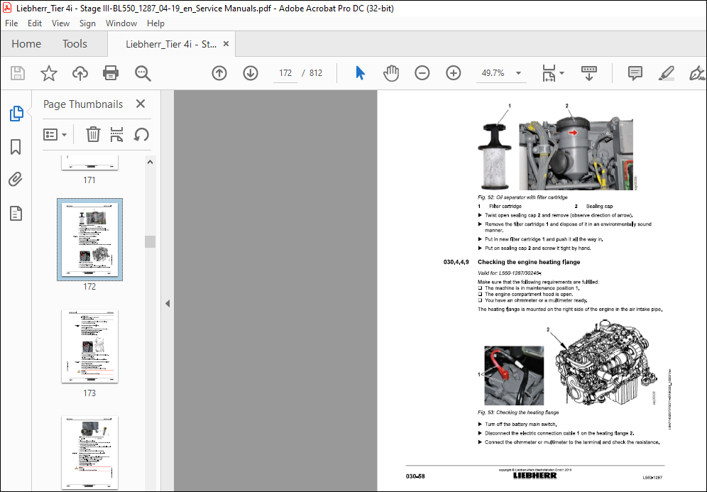
TABLE OF CONTENTS:
Liebherr L 550 1287 Wheel Loader Service Manual – PDF DOWNLOAD
010.1 Safety instructions 010-4
0101.1 General safety instructions 010-4
010.1.2 Instructions on preventing crushing injuries and burns 010-5
010.1.3 Instructions on preventing fires and explosions 010-5
010.14 Safety instructions for start-up 010-6
0101.5 Safety precautions during start-up 010-6
010.1.6 Instructions for safe working 010-7
010.1.7 Safety instructions for driving on slopes 010-8
0101.8 Parking safely 010-8
010.1.9 Transporting the machine safely 010-8
010.1.10 Towing the machine safely 010-9
010.1.11 Measures for ensuring safe maintenance 010-9
010.1.12 Safety instructions for maintenance work on machines with hydro
accumulators 010-12
010.1.13 Safety instructions for welding work on the machine 010-12
010.1.14 Safety instruction for working on the working attachment 010-12
010.1.15 Safety instructions for transporting the machine by crane 010-13
010.1.16 Safe maintenance of hydraulic hoses and hose lines 010-13
010.1.17 Roll over protective structure (ROPS) and falling object protection
structure (FOPS) 010-14
010.1.17.1 Preventing accidents 010-14
010.1.17.2 Preventing injuries 010-14
010.1.18 Attachments and accessories 010-14
010.1.19 Protection against vibrations 010-15
010.1.20 See and be seen 010-15
010.1.20.1 Field of view and visual aids 010-15
010.1.20.2 Measures during operation. 010-16
010.1.20.3 Modifications to the machine 010-16
010.1.21 Danger area of the machine 010-16
010.2.1 Special tools in general 010-18
010.2.2 Special tools for Liebherr diesel engines 010-19
010.2.3 Special tools, hydraulic cylinder (Z kinematics) 010-20
010.2.4 Special tools, hydraulic cylinder (industrial machine) 010-20
010.2.56 Special tools for steering cylinders 010-21
010.2.6 Special tools for the electrical system 010-21
010.2.7 Special tools for the transmission 010-21
010.2.8 Special tools for front axle MT-L II 010-22
010.29 Special tools for rear axle MT-L II 010-22
010.2.10 Special tools for the air conditioning system 010-22
010.2.11 Special tools for Grammer driver’s seat 010-23
010.2.12 Special tools for cab glazing 010-23
010.2.13 Special tools for the central lubrication system (Liebherr) 010-23
010.2.14 Special tools for the central lubrication system (Groeneveld) 010-24
Standards and regulations 010-25
010.3.1 Prestressing forces and tightening torques for bolts with metric
010.3.1.1 Range of application and purpose 010-25
010.3.1.2 Other applicable documents 010-25
010.3.1.3 Modifications and descriptions 010-26
010.3.1.4 Tightening torques 010-26
010.3.2 Liebherr standards for assembly instructions and tightening torques010-32
Preservation guidelines 010-33
010.4.1 General information 010-33
010.4.2 Machine out of service for an unknown period of time 010-33
010.4.3 Putting the machine out of service 010-34
010.4.3.1 Out of service for up to 2 months 010-34
0104.3.2 Out of service for up to 12 months 010-35
0104.3.3 Out of service for longer than 12 months 010-36
010.4.4 Putting back into service 010-36
020.1 Overall machine 020-5
020.1.1 Complete machine with bucket (Z lift arms)
L550-1287/30245-; 020-5
020.1.2 Complete machine with bucket (industrial lift arms)
L550-1287/30245-; 020-6
020.1.3 Attachment: Light material bucket
L550-1287/30245-; 020-8
020.14 Attachment: High dump bucket
L550-1287/30245-; 020-10
020.1.5 Attachment: Forklift
L550-1287/30245-; 020-11
020.1.6 Attachment: Timber grabber
L550-1287/30245-; 020-13
020.2 Drive group 020-15
020.2.1 Diesel engine
L550-1287/30245-; 020-15
020.2.2 Diesel particulate filter temperature sensors
L550-1287/30245-; 020-16
020.2.3 Fuel tank
L550-1287/30245-; 020-17
020.24 Fuel pre-filter (separator filter)
L550-1287/30245-; 020-17
020.2.5 Fuel fine filter
L550-1287/30245-; 020-17
020.2.6 Air filter vacuum switch
L550-1287/30245-; 020-17
020.2.7 Clutch
L550-1287/30245-; 020-18
0202.8 Splitter box
L550-1287/30245-; 020-18
020.3 Cooling system 020-19
020.3.1 Fan gear pump
L550-1287/30245-; 020-19
020.3.2 Fan gear motor
L550-1287/30245-; 020-19
020.3.3 Hydraulic oil temperature sensor B8
L550-1287/30245-; 020-19
020.4 Working hydraulics 020-20
020.4.1 Working hydraulics pump
L550-1287/30245-; 020-20
0204.2 Control valve block
L550-1287/30245-; 020-20
020.4.4 Pilot control hydro accumulator
020.4.5 Stabilisation module
020.4.6 Ride control hydro accumulator
020.4.7 Z kinematics and industrial lift arms lift cylinder
020.4.8 Z kinematics tilt cylinder
020.4.9 Industrial lift arms tilt cylinder
Travel hydraulics 020-23
020.5.1 Travel pump
020.5.2 Travel motor 1
020.5.3 Travel motor 2
020.5.4 Variable displacement motor scavenging gear pump
Hydraulic components 020-25
020.6.1 Filter unit
020.6.2 Breather filter
Steering system 020-26
020.7.1 Steering pump
020.7.2 Servostat
020.7.3 Steering cylinder
020.7.4 Steering cylinder pressure relief valve
020.7.5 Steering damper hydro accumulator
020.7.6 Emergency steering pump
020.7.7 Emergency steering pressure switch B3
Service manual Contents
020.7.8 Emergency steering check pressure switch B3a
L550-1287/30245-; 020-28
020.8 Brake system 020-29
0208.1 Brake system gear pump
L550-1287/30245-; 020-29
020.8.2 Compact brake valve
L550-1287/30245-; 020-29
0208.3 Service brake hydro accumulator
L550-1287/30245-; 020-29
020.8.4 Brake light pressure switch B12
L550-1287/30245-; 020-29
0208.5 Accumulator charge pressure switch B19
L550-1287/30245-; 020-30
020.8.6 Parking brake hydro accumulator
L550-1287/30245-; 020-30
0208.7 Overspeed protection solenoid valve Y16
L550-1287/30245-; 020-30
020.9 Electrical system 020-31
0209.1 Central control unit (Master 4)
L550-1287/30245-; 020-31
020.9.2 Input module
L550-1287/30245-; 020-31
020.9.3 Output module
L550-1287/30245-; 020-31
020.94 Battery
L550-1287/30245-; 020-32
0209.5 Voltage transformer
L550-1287/30245-; 020-32
020.9.6 Reversing camera
L550-1287/30245-; 020-32
020.10 Gearbox 020-34
020.10.1 Transmission
L550-1287/30245-; 020-34
2 020.10.2 Gear shifting solenoid valves
g L550-1287/30245-; 020-35
g 020.10.3 Speed sensors
s L550-1287/30245-; 020-35
§ 020.10.4 Transmission gear pump
£ L550-1287/30245-; 020-35
: 020.11 Axles and drive shafts 020-36
3 020.11.1 Front axle
L550-1287/30245-; 020-36
020.112 Rear axle
L550-1287/30245-; 020-3
020.11.4 Rear drive shaft
L550-1287/30245-; 020-37
020.11.5 Tyres
L550-1287/30245-; 020-37
020.11.5.2 Tyres for timber handling 020-39
020.11.5.3 Special tyres 020-39
020.11.5.4 Tyres for machines with optional accessories 020-40
020.12 Steel parts of the basic machine 020-41
020.12.1 Ballast weight
L550-1287/30245-; 020-41
020.13 Working attachment 020-42
020.13.1 Lift arms with Z kinematics
L550-1287/30245-; 020-42
020.13.2 Industrial machine lift arms
L550-1287/30245-; 020-43
020.14 Operator’s cab, heating and air conditioning 020-44
020.14.1 Heating, air conditioning
L550-1287/30245-; 020-44
020.14.2.1 Air conditioning 020-44
020.14.3.1 Air conditioning compressor 020-44
020.14.4 Dryer
L550-1287/30245-; 020-44
020.14.5 Air conditioning pressure switch
L550-1287/30245-; 020-45
020.14.6 Anti-icing temperature sensor
L550-1287/30245-; 020-45
020.15 Lubrication system 020-46
020.15.1 Central lubrication system (Liebherr)
L550-1287/30245-; 020-46
020.15.1.1 Central lubrication pump 020-46
020.15.1.2 Progressive distributor 020-46
030 Maintenance 030-1
030.1 Maintenance and inspection schedule 030-10
030.2 Filling quantities and lubrication chart 030-15
030.2.1 Recommended lubricants
L550-1287/30245-; 030-15
030.22 Recommended operating fluids
1 550-1287/30245-40348; 030-16
030.2.3 Recommended operating fluids
L550-1287/40349-; 030-16
030.3 Lubricants and fuels 030-17
030.3.1 General information on lubricants and fuels 030-17
030.3.1.1 General questions 030-17
030.3.1.2 Safety data sheets 030-17
030.3.1.3 Technical data sheets 030-17
030.3.1.4 Specific Liebherr standards 030-17
030.3.2 General information on changing lubricants and fuels 030-17
030.3.3 Converting hydraulic system from mineral oils to biodegradable
hydraulic fluids 030-18
030.34 Diesel fuels
L550-1287/30245-; 030-18
030.3.4.1 Specification 030-18
030.3.4.2 Sulphur content of the diesel fuel, lubricity 030-18
030.3.4.3 Diesel fuel at low temperatures (winter operation) 030-19
030.3.4.4 Flow improvers at low temperatures 030-19
030.3.5 Diesel fuels for diesel engines without emission-type approval
L550-1287; 030-19
030.3.5.1 Minimum quality requirement 030-19
030.3.6 Lubricating oils for diesel engines
L550-1287/30245-; 030-20
030.3.6.1 Lubricating oil quality 030-20
030.3.6.2 Lubricating oil viscosity 030-20
030.3.6.3 Complicating factors affect the oil change 030-21
030.3.7 Engine oils for diesel engines without emission-type approval
L550-1287; 030-21
030.3.7.1 Liebherr recommendation 030-21
030.3.7.2 Other approved engine oils 030-21
030.3.7.3 Minimum quality requirement 030-22
030.3.7.4 Changing intervals 030-22
030.3.7.5 Complicating factors 030-22
030.3.8 Refrigerant
L 550-1287; 030-22
030.3.9 Coolants for diesel engines
L550-1287/30245-40348; 030-23
030.3.9.1 General recommendations 030-23
030.3.9.2 Water (fresh water) 030-23
030.3.9.3 Coolant mixing ratio 030-23
030.3.9.4 Permissible antifreeze and corrosion inhibitors 030-24
030.3.9.5 Corrosion inhibitors without antifreeze 030-24
030.3.10 Coolants for diesel engines
L550-1287/40349-; 030-25
030.3.10.1 General recommendations 030-25
030.3.10.2 Water (fresh water) 030-25
030.3.10.3 Coolant – Mixing ration 030-26
030.3.10.4 Approved antifreeze and corrosion inhibitors 030-26
030.3.10.56 Permissible premixed antifreeze/corrosion inhibitors 030-26
030.3.10.6 Corrosion inhibitors without antifreeze 030-27
030.3.11 Hydraulic oil
L550-1287/30245-; 030-27
030.3.11.1 Liebherr hydraulic oil 030-28
030.3.11.2 Using engine oil as hydraulic oil 030-28
030.3.11.3 Warming up 030-29
030.3.11.4 Biodegradable hydraulic oils 030-29
030.3.11.5 Changing the oil, analysing the oil, changing filters 030-30
030.3.12 Lubricating oils for splitter boxes
L550-1287/30245-; 030-31
030.3.13 Lubricating oils for transmissions
L550-1287/30245-; 030-32
030.3.14 Lubricating oils for axles
L550-1287/30245-; 030-33
030.3.15 Lubrication grease and other lubricants
L550-1287/30245-; 030-33
030.3.15.1 Minimum quality requirements 030-34
030.3.15.2 Liebherr lubrication grease 030-34
030.4 Maintenance tasks 030-36
030.4.1 Safety precautions
L550-1287/30245-; 030-36
030.4.2 Preparatory tasks for maintenance 030-36
030.4.2.1 Maintenance positions
L550-1287/30245-; 030-37
030.4.2.2 Opening the service accesses
L550-1287/30245-; 030-38
030.4.2.3 Turning off the battery main switch
1L550-1287/30245-; 030-40
030.4.3 Overall machine 030-41
L550-1287/30245-; 030-41
030.4.3.2 Removing loose parts, dirt, ice and snow from the
machine
L550-1287/30245-; 030-41
030.4.3.3 Cleaning the machine
L550-1287/30245-; 030-41
030.4.3.4 Checking the machine for leaks
L550-1287/30245-; 030-43
030.4.3.5 Making sure the bolted connections are tight
L550-1287/30245-; 030-43
030.4.3.6 Corrosion protection system for use with salt and arti-
ficial fertilisers (optional): Carrying out corrosion
protection
L550-1287/30245-; 030-43
030.4.3.7 Qil analyses
L550-1287/30245-; 030-44
0304.4 Drive group 030-50
030.4.4.1 Checking the engine oil level
L550-1287/30245-; 030-50
030.44.2 Changing diesel engine oil
L550-1287/30245-; 030-51
030.4.4.3 Changing the engine oil filter
L550-1287/30245-; 030-52
030.4.4.4 Checking the V-ribbed belt on the engine
L550-1287/30245-; 030-53
030.4.4.5 Changing the V-ribbed belt on the engine
L550-1287/30245-; 030-53
030.44.6 Checking the mounting and sensor cable connec-
tions of the engine control units
L550-1287/30245-; 030-55
030.4.4.7 Checking the engine valve clearance
L550-1287/30245-; 030-55
030.4.4.8 Diesel engine oil separator – changing filter cartridge
L550-1287/30245-; 030-57
030.4.4.9 Checking the engine heating flange
L550-1287/30245-; 030-58
030.4.4.10 Changing the engine heating flange
L550-1287/30245-; 030-59
030.4.4.11 Draining off condensate and sediment from the fuel
tank
L550-1287/30245-; 030-59
030.4.4.12 Draining off condensate from the Separ fuel pre-filter
L550-1287/30245-; 030-60
030.4.4.13 Changing the Separ fuel pre-filter insert
L550-1287/30245-; 030-61
030.4.4.15 Bleeding the fuel system
030.4.4.16 Cleaning the air filter service cover and dust
030.4.4.17 Checking the air suction system for leaks and tight
030.4.4.18 Cleaning or changing the main filter element
030.4.4.19 Changing the air filter safety element
030.4.4.20 Checking the ail level in the splitter box
030.4.4.21 Changing the splitter box oil
030.4422 Checking the exhaust system for leaks and tight
030.4.4.23 Cleaning or changing the diesel particulate filter
Cooling system 030-80
030.4.5.1 Checking the coolant antifreeze and corrosion inhib-
030.4.5.2 Cleaning the cooling system
030.4.5.3 Changing the coolant
0304.5.4 Changing the coolant
Working hydraulics 030-90
030.4.6.1 Lubricating the solenoids, universal joints and
Hydraulic components 030-90
030.4.7.1 Checking the oil level in the hydraulic tank
030.4.7.2 Checking and cleaning the magnetic rod on the
030.4.7.3 Draining off condensate and sediment from the
L550-1287/30245-; 030-94
030.4.7.5 Changing the hydraulic tank breather filter
L550-1287/30245-; 030-95
030.4.7.6 Hydraulic tank – changing the oil in the hydraulic
system
L550-1287/30245-; 030-96
0304.8 Steering system 030-97
030.4.8.1 Testing the steering
L550-1287/30245-; 030-97
030.4.8.2 Lubricating the bearing points on the steering cylin-
ders
L550-1287/30245-; 030-98
030.4.9 Brake system 030-98
030.4.9.1 Testing the service brake and parking brake
L550-1287/30245-; 030-98
030.4.9.2 Checking the service brake discs for wear
L550-1287/30245-; 030-99
030.4.9.3 Checking the gap and wear on the parking brake
linings
L550-1287/30245-; 030-102
0304.10 Electrical system 030-107
030.4.10.1 Checking the lights
L550-1287/30245-; 030-107
030.4.10.2 Checking the batteries, fluid level and terminals
L550-1287/30245-; 030-108
030.4.10.3 Changing the travel direction rocker switch and cap
(optional) on the control lever
L550-1287/30245-; 030-110
0304.11 Gearbox 030-112
030.4.11.1 Checking the transmission oil level
L550-1287/30245-; 030-112
030.4.11.2 Changing the transmission oil
L550-1287/30245-; 030-113
030.4.11.3 Changing the transmission oil filter
L550-1287/30245-; 030-114
030.4.12 Axles and drive shafts 030-115
030.4.12.1 Checking the axle oil levels
L550-1287/30245-; 030-115
030.4.12.2 Changing the axle oil
L550-1287/30245-; 030-115
030.4.12.3 Checking the cardan shafts
L550-1287/30245-; 030-117
copyright ® Liebherr-Werk Bischofshofen GmbH 2019
L550-1287 LIEBHERR 15
Contents Service manual
030.4.12.4 Checking the tyre pressure
L550-1287/30245-; 030-117
0304.12.5 Checking the wheel tightness
1L550-1287/30245-35541; 030-117
030.4.12.6 Checking the wheel tightness
L550-1287/35542-; 030-118
030.4.13 Steel parts of the basic machine 030-119
030.4.13.1 Lubricating the articulation bearing and the rear axle
oscillating bearing
L550-1287/30245-; 030-119
030.4.13.2 Covering – lubricating locks and hinges
L550-1287/30245-; 030-120
030.4.13.3 Greasing the rear section cover lower hinges
L550-1287/30245-; 030-120
030.4.14 Working attachment 030-121
030.4.14.1 Lubricating the lift arms and attachment
L550-1287/30245-; 030-121
0304.14.2 Checking the bucket bearing seals and the bearing
bushings on the lift arms
L550-1287/30245-; 030-122
030.4.14.3 Checking the lift arm bucket stops
L550-1287/30245-; 030-124
030.4.14.4 Lubricating and testing the quick-change device
L550-1287/30245-; 030-125
030.4.15 Operator’s cab, heating and air conditioning 030-126
030.4.15.1 Lubricating the elongated hole on the accelerator
pedal and checking the bearing
L550-1287/30245-; 030-126
0304.15.2 Cleaning the fresh and recirculated air filters
L550-1287/30245-; 030-127
0304.15.3 Changing the fresh and recirculated air filters
L550-1287/30245-; 030-129
030.4.15.4 Checking the condition and function of the safety belt
L550-1287/30245-; 030-130
0304.15.5 Checking and topping up the windscreen washer
reservoir
L550-1287/30245-; 030-130
030.4.156 Lubricating the cab door hinges
L550-1287/30245-; 030-131
030.4.15.7 Checking the seals on the driver’s cab
L550-1287/30245-; 030-131
030.4.15.8 Heating and air conditioning unit: Testing the function
L550-1287/30245-; 030-131
030.4.16 Lubrication system 030-133
level
L550-1287/30245-; 030-133
the lubrication system
L550-1287/30245-; 030-134
at the bearing points (grease collars) of the lubrica-
L550-1287/30245-; 030-134
030.5 Testing and adjustment checklist
L550-1287/30245-; 030-135
030.6 Testing and adjustment tasks 030-140
0306.1 Safety precautions
L550-1287/30245-; 030-140
030.6.2 Overall machine 030-141
030.6.2.1 Preparatory tasks for testing and adjustment
L550-1287/30245-; 030-141
030.6.2.2 Bringing the machine up to operating temperature
L550-1287/30245-; 030-142
0306.3 Drive group 030-143
030.6.3.1 Calibrating the pedals
L550-1287/30245-; 030-143
030.6.3.2 Checking the engine speed
L550-1287/30245-; 030-143
030.6.3.3 Engine: Reading the service files
L550-1287/30245-; 030-144
030.6.3.4 Diesel particulate filter: Performing service regenera-
tion.
L550-1287/30245-; 030-145
0306.4 Cooling system 030-147
030.6.4.1 Fan gear motor proportional pressure relief valve
L550-1287/30245-; 030-147
0306.5 Working hydraulics 030-149
030.6.5.1 Working hydraulics pump flow regulator (standby
pressure)
L550-1287/30245-; 030-149
030.6.5.2 Working hydraulics pump, flow regulator (differential
pressure)
L550-1287/30245-; 030-151
030.6.5.3 Working hydraulics pump, power regulator
L550-1287/30245-; 030-152
030.6.5.4 Z kinematics control valve block secondary pressure
relief valves
L550-1287/30245-; 030-153
030.6.5.6 Z kinematics control valve block LS pressure cut-off
030.6.5.7 Industrial lift arm control valve block secondary pres-
030.6.5.8 Industrial lift arm control block, primary pressure
030.6.5.9 Industrial lift arms control valve block LS pressure
030.6.5.10 Stabilisation module cut-off function
030.6.5.11 Nitrogen filling of ride control hydro accumulator
030.6.5.12 Testing the Z kinematics control valve block for
Hydraulic components 030-167
030.6.6.1 Checking the hydraulic lines for damage
Travel hydraulics 030-172
030.6.7.1 Travel pump, high pressure sensor
030.6.7.2 Travel pump replenishing pressure relief valve
0306.7.3 Pressure relief and replenishing valves of the travel
030.6.7.4 Travel pump pressure cut-off
030.6.7.5 Travel pump block curve calibration
0306.7.6 Travel motors, automatic calibration
030.6.7.7 Engine output
Steering system 030-183
030.6.8.1 Steering pump LS pressure cut-off valve
030.6.8.2 Steering pump flow regulator (standby pressure)
0306.9 Brake system 030-186
030.6.9.1 Compact brake valve, hydro accumulator charging
function
L550-1287/30245-; 030-186
030.6.9.2 Service brake pressure
L550-1287/30245-; 030-187
030.6.9.3 Service brake hydro accumulator capacity
L550-1287/30245-; 030-188
030.6.9.4 Accumulator charge pressure switch shift pressure
L550-1287/30245-; 030-190
030.6.10 Electrical system 030-191
030.6.10.1 Central control unit (Master4) Creating a Servicefile
L550-1287/30245-; 030-191
030.6.10.2 Central control unit (Master4): software update
1550-1287; 030-194
030.6.10.3 Setting the IP addresses of the central control unit
(Master4)
L550-1287/30245-; 030-196
030.6.10.4 Resetting the central control unit (Master4)
L550-1287/30245-; 030-199
030.6.10.5 Testing the CAN line
L550-1287/30245-; 030-200
030.6.10.6 Addressing the CAN module and checking the
system information
L550-1287/30245-; 030-204
030.6.11 Gearbox 030-208
030.6.11.1 Control valve block shift pressure
L550-1287/30245-; 030-208
030.6.11.2 Nitrogen filling of transmission hydro accumulator
L550-1287/30245-; 030-208
030.6.12 Operator’s cab, heating and air conditioning 030-210
030.6.12.1 Checking the pressure and temperature conditions of
the air conditioning unit
L550-1287/30245-; 030-210
030.6.12.2 Calibrating the display (Display4)
L550-1287/30245-; 030-211
030.6.12.3 Formatting the display and reinstalling the software
(Display4)
L550-1287/30245-; 030-212
0306.13 Options 030-214
030.6.13.1 Checking the LIDAT connection status
L550-1287/30245-; 030-214
L550-1287; 030-216
040 Drive group 040-1
040.1 Engine 040-3
040.1.1 Diesel engine overview
L550-1287/30245-; 040-3
040.1.2 Electrical components on the engine
L550-1287/30245-; 040-7
040.1.3 Speed sensor for crankshaft
L550-1287/30245-; 040-8
040.1.4 Camshaft speed sensor
L550-1287/30245-; 040-9
040.1.5 Fuel system 040-10
040.1.5.1 Overview of the fuel system
1L550-1287/30245-; 040-11
040.1.5.2 Fuel level sensor
L550-1287/30245-; 040-12
040.1.6 Air filter system 040-12
040.1.6.1 Air filter
1L550-1287/30245-; 040-13
040.1.6.2 Vacuum switch
L550-1287/30245-; 040-14
040.1.7 Exhaust system 040-14
040.1.7.1 Overview of the diesel particulate filter
L550-1287/30245-; 040-15
040.1.7.2 Diesel oxidation catalyst (DOC)
1L550-1287/30245-; 040-20
040.1.7.3 Diesel particulate filter module
L550-1287/30245-; 040-21
040.1.7.4 Removing the diesel particulate filter
L550-1287; 040-21
040.1.7.5 Installing the diesel particulate filter
L550-1287; 040-23
040.2 Clutch
L550-1287/30245-; 040-27
040.3 Splitter box
L550-1287/30245-; 040-29
050 Cooling system 050-1
050.1 Overview of the cooling system
L550-1287/30245-; 050-2
050.2 Cooling system hydraulics 050-3
050.2.2 Fan gear pump
L550-1287/30245-; 050-5
0502.3 Fan gear motor
L550-1287/30245-; 050-7
050.3 Cooling system electronics 050-11
050.3.1 Electric fan speed control
L550-1287/30245-; 050-11
050.3.2 Hydraulic oil temperature sensor
L550-1287/30245-; 050-13
060 Working hydraulics 060-1
060.1 Overview of the working hydraulics
L550-1287/30245-; 060-2
060.2 Pilot control 060-9
060.2.1 Pilot control unit
L550-1287/30245-; 060-9
060.2.2 Pilot control solenoid valve
L550-1287/30245-; 060-14
060.2.3 Pilot control hydro accumulator
L550-1287/30245-; 060-15
060.3 Ride control 060-16
060.3.1 Stabilisation module
L550-1287/30245-; 060-16
060.3.2 Ride control hydro accumulator
L550-1287/30245-; 060-20
060.4 Hydraulic cylinders of the working hydraulics 060-21
0604.1 Hydraulic cylinders for Z kinematics 060-21
060.4.1.1 Z kinematics lift cylinder
L550-1287/30245-; 060-21
060.4.1.2 Z kinematics tilt cylinder
L550-1287/30245-; 060-22
0604.2 Hydraulic cylinders for industrial lift arms 060-23
060.4.2.1 Lift cylinder for industrial lift arms
L550-1287/30245-; 060-23
060.4.2.2 Industrial lift arms tilt cylinder
L550-1287/30245-; 060-24
070 Travel hydraulics 070-1
070.1 Travel hydraulics overview
L550-1287/30245-38936; 070-2
070.3 Variable displacement pump
L550-1287/30245-; 070-14
080 Hydraulic components 080-1
080.1 Hydraulic tank 080-2
080.1.1 Overview of the hydraulic tank
L550-1287/30245-; 080-2
080.1.2 Filter unit
L550-1287/30245-; 080-5
080.1.3 Breather filter
L550-1287/30245-; 080-10
090 Steering system 090-1
090.1 Steering system overview
L550-1287/30245-34309; 090-2
090.2 Steering system overview
L550-1287/34310-35231; 090-8
090.3 Steering system overview
L550-1287/35232-; 090-14
090.4 Steering pump
L550-1287/30245-; 090-17
090.5 Servostat
L550-1287/30245-; 090-24
090.6 Steering cylinder 090-29
090.6.1 Steering cylinder overview
L550-1287/30245-; 090-29
090.6.2 Steering cylinder pressure relief valve
L550-1287/34310-; 090-31
090.6.3 Steering damper hydro accumulator
L550-1287/30245-; 090-32
090.7 Emergency steering 090-34
090.7.1 Emergency steering overview
L550-1287/30245-; 090-34
090.7.2 Emergency steering pump
L550-1287/30245-; 090-38
090.7.3 Emergency steering electronics 090-40
090.7.3.1 Emergency steering pressure switch
L550-1287/30245-; 090-40
090.7.3.2 Emergency steering check pressure switch
L550-1287/30245-; 090-41
100 Brake system 100-1
100.1 Overview of the brake system
L550-1287/30245-; 100-2
100.2 Service brake and parking brake 100-9
100.2.1 Compact brake valve
L550-1287/30245-; 100-9
100.3 Service brake 100-13
100.3.1 Service brake hydro accumulator
L550-1287/30245-; 100-13
100.3.2 Brake light pressure switch
L550-1287/30245-; 100-14
100.3.3 Accumulator charge pressure switch
L550-1287/30245-; 100-15
100.4 Parking brake 100-16
100.4.1 Parking brake
L550-1287/30245-; 100-16
100.4.2 Disc brake
L550-1287/30245-; 100-18
100.4.3 Parking brake hydro accumulator
L550-1287/30245-; 100-21
100.5 Overspeed protection 100-22
100.5.1 Overview of the overspeed protection system
L550-1287/30245-; 100-22
100.5.2 Overspeed protection solenoid valve
L550-1287/30245-; 100-25
110 Electrical system 110-1
110.1 Overview of the electrical system
L550-1287/30245-; 110-2
110.2 Lighting
1 550-1287/30245-; 110-7
110.3 Circuit diagrams
L550-1287/30245-; 110-9
110.4 Electronic control unit 110-11
110.4.1 Central control unit (Master4)
L550-1287/30245-; 110-11
110.42 Modules 110-16
1104.21 Input modules
L550-1287/30245-; 110-15
copyright ® Liebherr-Werk Bischofshofen GmbH 2019
L550-1287 LIEBHERR 23
Contents Service manual
110.4.2.2 Output modules
L550-1287/30245-; 110-18
110.5 Electrical components of the driver’s cab 110-23
110.5.1 Overview of electrical components in the cab
L550-1287/30245-; 110-23
110.5.2 Fuse and relay board
L550-1287/30245-; 110-24
110.6 Electrical components in the rear section 110-30
110.6.1 Battery installation
L550-1287/30245-; 110-30
110.7 Rear area monitoring with camera 110-32
110.7.1 Overview of rear area monitoring with camera
L550-1287/30245-; 110-32
110.7.2 Camera
L550-1287/30245-; 110-33
120 Gearbox 120-1
120.1 Overview of the transmission
L550-1287/30245-; 120-2
120.2 Mechanical transmission
L550-1287/30245-; 1204
120.3 Transmission hydraulics 120-10
120.3.1 Overview of the hydraulic control system
L550-1287/30245-; 120-10
120.3.2 Transmission gear pump
L550-1287/30245-; 120-14
120.3.3 Control valve block
L550-1287/30245-; 120-15
120.3.4 Transmission hydro accumulator
L550-1287/30245-; 120-16
120.4 Transmission electronics 120-17
120.4.1 Overview of the electronic control system
L550-1287/30245-; 120-17
120.4.2 Gear shifting solenoid valves
L550-1287/30245-; 120-19
120.4.3 Speed sensors
L550-1287/30245-; 120-20
120.4.4 Gear oil temperature switch
L550-1287/30245-; 120-21
130 Axles and drive shafts 130-1
130.1 Axles 130-2
130.1.2 Rear axle
L550-1287/30245-; 130-7
130.2 Cardan shafts 130-8
130.2.1 Front cardan shaft
L550-1287/30245-; 130-8
130.2.2 Rear cardan shaft
L550-1287/30245; 130-9
140 Steel parts of the basic machine 140-1
140.1 Vehicle frame 140-2
140.1.1 Articulation bearing
L550-1287/30245-; 140-2
140.1.2 Oscillating bearing
L550-1287/30245-; 140-4
140.1.3 Articulation lock
L550-1287/30245-; 140-4
140.2 Ballast weight
L550-1287/30245-; 140-6
140.3 Cab access
L550-1287/30245-; 140-7
150 Working attachment 150-1
150.1 Lift arms for Z kinematics 150-2
160.1.1 Overview of z-bar lift arm kinematics
L550-1287/30245-; 150-2
160.1.2 Pin bearing 150-3
150.1.2.1 Standard bearing
L550-1287/30245-; 150-3
160.1.2.2 Bucket bearing
L550-1287/30245-; 150-5
2 150.1.2.3 Removing the bucket bearing
8 L550-1287/30245-; 150-6
g 150.1.2.4 Installing the bucket bearing
g L550-1287/30245-; 150-9
§ 150.2 Quick coupler 150-12
§ 150.2.1 Quick-change device (optional)
3 L550-1287/30245-; 150-12
3
2 150.3 Bucket
L550-1287/30245-; 150-14
150.4 Forklift
L550-1287/30245-; 150-15
Contents Service manual
160.1 Overview of the cab, heating and air conditioning unit
L550-1287/30245-; 160-3
160.2 Display and control elements 160-6
160.2.1 Electrical components in the control panel 160-6
160.2.1.1 Overview of electrical components in the control
panel
L550-1287/30245-; 160-6
160.2.1.2 Control unit for main functions
L550-1287/30245-; 160-6
160.2.1.3 Electric control unit
L550-1287/30245-; 160-8
160.2.1.4 Starter switch
L550-1287/30245-; 160-12
160.2.2 Touch screen display
L550-1287/30245-; 160-13
160.2.3 Control lever
L550-1287/30245-; 160-15
160.3 Heating, ventilation, air conditioning 160-18
160.3.1 Heating and air conditioning unit 160-18
160.3.1.1 Heating and air conditioning unit
L550-1287/30245-; 160-18
160.3.1.2 Blower
L550-1287/30245-; 160-20
160.3.2 Heating/air conditioning electronics
L550-1287/30245-; 160-21
160.4 Air conditioning 160-23
160.4.1 Air conditioning compressor
L550-1287/30245-; 160-23
160.4.2 Condenser
L550-1287/30245-; 160-24
160.4.3 Dryer
L550-1287/30245-; 160-26
160.4.4 Air conditioning pressure switch
L550-1287/30245-; 160-27
160.4.5 Evaporator
L550-1287/30245-; 160-28
160.4.6 Anti-icing temperature sensor
L550-1287/30245-; 160-29
160.4.7 Automatic air conditioning 160-29
L550-1287/30245-; 160-29
sensor
L550-1287/30245-; 160-31
160.4.7.3 Outside temperature sensor
L550-1287/30245-; 160-31
160.4.7.4 Sun sensor
L550-1287/30245-; 160-32
Lubrication system 170-1
170.1 Liebherr automatic central lubrication system 170-2
170.1.1 Overview of Liebherr automatic central lubrication system
L550-1287/30245-; 170-2
170.1.2 Liebherr central lubrication pump
L550-1287/30245-; 170-6
170.1.3 Progressive distributor MX-F
L550-1287/30245-; 170-10
Options 190-1
190.1 Diesel engine without emission type approval
190.2 LiDAT 190-3
190.3 Refuelling system
190.4 Weighing device (Liebherr)
Diagnosis 200-1
200.1 Malfunctions 200-2
200.2.1 Replacing fuses 200-4
200.2.1.1 Fuses in the battery compartment 200-4
VIDEO PREVIEW OF THE MANUAL:
PLEASE NOTE:
- This is the SAME exact manual used by your dealers to fix your vehicle.
- The same can be yours in the next 2-3 mins as you will be directed to the download page immediately after paying for the manual.
- Any queries / doubts regarding your purchase, please feel free to contact [email protected]
S.V


