

Kubota KX61-3 KX71-3 Excavator Workshop Manual – PDF DOWNLOAD
DESCRIPTION:
Kubota KX61-3 KX71-3 Excavator Workshop Manual – PDF DOWNLOAD
General
a. Sales feature
Product concept : Comfort in conpact
(1) Grade up the basic performance; Digging, filling back and lifting capacity
(2) Grade up product feature to differentiate competitor; Digital meter, hose protection
Workability :Bucket digging force improvement
Variable pump adoption
Boom and SP simultaneous operation
The maximum digging depth priority
High level stability
Maintenance: Blade hose division
New digital meter adoption
Amenity :Much easier access into cabin
Cabin width expansion
Operativity :Straight travel adoption
Smoother operation
Safety: Engine safety start
Travel lock system
ROPS, FOPS standard equipment
TABLE OF CONTENTS:
Kubota KX61-3 KX71-3 Excavator Workshop Manual – PDF DOWNLOAD
WSM_KX61-3_71-3_Mechanism…………………………………………………….. 1
CONTENTS………………………………………………………………… 3
I. General………………………………………………………………. 4
a. Sales feature……………………………………………………… 5
b. Difference between KX61-3 and KX71-3…………………………………. 5
c. Quick chart for selling points : KX61-3, KX71-3……………………….. 6
d. Comparison to competitors;EU – version……………………………….. 7
e. Compornents compatibility…………………………………………… 8
f. Machine specifications……………………………………………… 9
g. Machine weight…………………………………………………….. 10
h. Quality specifications……………………………………………… 11
II. Machine Body…………………………………………………………. 23
a. Main component…………………………………………………….. 24
1. Pump coupling………………………………………………….. 24
2. Bucket : Kubota standard bucket………………………………….. 25
3. Bucket installation relevant dimensions…………………………… 27
4. Swing bracket………………………………………………….. 29
5. Swivel bearing…………………………………………………. 30
6. Idler and tension spring : Rubber track and iron track……………… 31
7. Track roller…………………………………………………… 32
8. Rubber track…………………………………………………… 33
9. Iron track…………………………………………………….. 34
10. Track conversion………………………………………………. 35
b. Water and oil quantity……………………………………………… 36
III. Engine……………………………………………………………… 37
a. Engine Specifications………………………………………………. 38
b. Engine electric components………………………………………….. 38
c. Performance curve : KX61-3 EU, V1505-E2-BH-9-EU……………………….. 39
d. Performance curve : KX71-3 EU, V1505-E2-BH-10 EU………………………. 40
e. Performance curve : KX71-3 PP, V1505-E2-BH-10…………………………. 41
IV. Hydraulic System……………………………………………………… 43
a. Hydraulic System Feature……………………………………………. 44
b. Hydraulic circuit diagram…………………………………………… 44
1. KX61-3: EU – version……………………………………………. 45
2. KX71-3: EU – version……………………………………………. 46
3. KX71-3: PP – version……………………………………………. 47
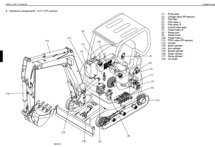
4. Hydraulic components ; KX71-PP-version……………………………. 48
c. Main pump…………………………………………………………. 49
1. Outer view…………………………………………………….. 49
2. structure……………………………………………………… 50
3. P-Q performance curve…………………………………………… 51
4. Pump Specifications, Type : PVD-1B-28P-8G3-4575A…………………… 51
d. Control valve assy…………………………………………………. 53
1. KX61-3: EU – version, Code No:RG248-61131, Maker: Hydro control……… 53
2. KX71-3: EU – version, Code No:RG448-61131, Maker: Hydro control……… 54
3. KX71-3: PP – version, Code No:RC348-61131, Maker: NABCO…………….. 55
4. Control valve section : KX71-3 PP – version (RB448-61131)…………… 56
e. Pilot valve……………………………………………………….. 60
1. EU – version…………………………………………………… 60
2. KTC, KCL, KTA-version…………………………………………… 61
3. Technical data : Travel motor……………………………………. 64
f. Travel motor………………………………………………………. 65
1. Structure……………………………………………………… 65
2. Circuit diagram………………………………………………… 67
g. Swivel motior……………………………………………………… 68
1. Technical data…………………………………………………. 68
2. Outer view…………………………………………………….. 69
3. Inner parts……………………………………………………. 70
4. Sectional view (KX61-3, 71-3 Swivel motor assy)……………………. 73
h. Cylinder………………………………………………………….. 75
1. Major size…………………………………………………….. 75
i. Rotary joint………………………………………………………. 76
j. Accessories of hydraulic components………………………………….. 77
1. Unload valve (Change valve) : North America and Oceanea – version……. 77
2. Change valve with accumulator : EU version………………………… 78
3. TPSS valve (Two pattern selection system)…………………………. 79
4. Oil cooler…………………………………………………….. 80
5. Pilot filter…………………………………………………… 81
6. Suction filter…………………………………………………. 82
7. Return filter………………………………………………….. 83
8. Check valve……………………………………………………. 84
k. Maintenance specification…………………………………………… 85
1. Main relief valve (at the measurement port on the machine)………….. 85
2. Overload relief valve (at the measurment port on the machine)……….. 85
3. Cylinder operating speed………………………………………… 86
4. Cylinder natural fall amount…………………………………….. 86
V. Electrical System……………………………………………………… 87
a. Development concept………………………………………………… 88
1. Background of Adoption of New Meter………………………………. 88
2. Features of New Meter…………………………………………… 88
3. Electrical system : Functional comparison : KX61-3, KX71-3………….. 90
b. Outline of Kubota ICS (Intelligent Control System)…………………….. 91
c. Operating Mode…………………………………………………….. 94
1. Outline……………………………………………………….. 94
2. LCD display list……………………………………………….. 95
d. Service mode menues………………………………………………… 98
1. Outline……………………………………………………….. 98
2. Service mode flow chart…………………………………………. 98
3. Main menues and functions……………………………………….. 99
e. Failure Diagnosis…………………………………………………..120
1. Failure display and diagnosis criteria…………………………….120
2. Fail record in EEPROM……………………………………………122
3. self-diagnosis of controller unit…………………………………125
4. Electrical component layout………………………………………131
5. Service Mode KX61-3, KX71-3(Non-AI Non- anti-theft Non-S/O) ver 1.13….132
f. Circuit wiring diagram………………………………………………133
1. KX61-3, KX71-3 Export (EU) (US)…………………………………..133
2. KX61-3, KX71-3 Export standard type……………………………….134
IMAGES PREVIEW OF THE MANUAL:
VIDEO PREVIEW OF THE MANUAL:

PLEASE NOTE:
- This is the SAME exact manual used by your dealers to fix your vehicle.
- The same can be yours in the next 2-3 mins as you will be directed to the download page immediately after paying for the manual.
- Any queries / doubts regarding your purchase, please feel free to contact [email protected]
S.V


