Kubota F2690E F2690 F3990 RCK60P-F39 RCK60R-F36 RCK72P-F39 RCK72R-F36 Workshop Manual – PDF DOWNLOAD
DESCRIPTION:
Kubota F2690E F2690 F3990 RCK60P-F39 RCK60R-F36 RCK72P-F39 RCK72R-F36 Workshop Manual – PDF DOWNLOAD
TO THE READER
This Workshop Manual tells the servicing personnel about the mechanism, servicing and
maintenance of the F2690E, F2690 and F3990, KUBOTA Mower RCK60P-F39, RCK60R-F36,
RCK72P-F39 and RCK72R-F36. It contains 4 parts: “Information”, “General”, “Mechanism” and
“Servicing”.
Information
This section primarily contains information below.
• Safety First
• Safety Decal
• Specification
• Dimension
General
This section primarily contains information below.
• Engine Identification
• Model Identification
• General Precautions
• Maintenance Check List
• Check and Maintenance
• Special Tools
Mechanism
This section contains information on the structure and the function of the unit. Before you continue
with the subsequent sections, make sure that you read this section.
Refer to the latest version of Workshop Manual (Code No. 9Y021-01870) for the diesel engine /
tractor mechanism that this workshop manual does not include.
Servicing
This section primarily contains information below.
• Troubleshooting
• Servicing Specifications
• Tightening Torques
• Checking, Disassembling and Servicing
Regarding the servicing of electric control system of V1505-T-E4 (F3990), refer to “Diagnosis
Manual V1505-T-E4 (9Y120-02490)”.
Regarding the servicing of Diesel Particulate Filter (DPF), refer to “DIESEL PARTICULATE FILTER
HANDLING MANUAL” (9Y111-08130).
- All illustrations, photographs and specifications contained in this manual are of the newest
information available at the time of publication. - KUBOTA reserves the right to change all information at any time without notice.
Since this manual includes many models, information or illustrations and photographs can show
more than one model.
TABLE OF CONTENTS:
Kubota F2690E F2690 F3990 RCK60P-F39 RCK60R-F36 RCK72P-F39 RCK72R-F36 Workshop Manual – PDF DOWNLOAD
F2690E,F2690,F3990,RCK60P-F39,RCK60R-F36,RCK72P-F39,RCK72R-F36…………………….. 1
TO THE READER…………………………………………………………….. 2
I INFORMATION…………………………………………………………….. 3
INFORMATION…………………………………………………………… 4
1. MACHINE………………………………………………………… 5
[1] SAFETY FIRST……………………………………………….. 5
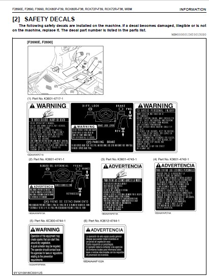
[2] SAFETY DECALS………………………………………………. 8
[3] SPECIFICATIONS……………………………………………… 15
[4] DIMENSIONS…………………………………………………. 16
2. MOWER………………………………………………………….. 17
[1] SAFETY DECALS………………………………………………. 17
[2] TERMINOLOGY………………………………………………… 19
[3] SPECIFICATIONS……………………………………………… 21
G GENERAL………………………………………………………………… 22
GENERAL………………………………………………………………. 23
1. IDENTIFICATION………………………………………………….. 24
[1] ENGINE AND MODEL SERIAL NUMBERS………………………………. 24
[2] E4 ENGINE………………………………………………….. 26
[3] CYLINDER NUMBER…………………………………………….. 26
2. GENERAL PRECAUTIONS……………………………………………… 27
3. HANDLING PRECAUTIONS FOR ELECTRICAL PARTS AND WIRING………………… 28
[1] WIRING…………………………………………………….. 28
[2] BATTERY……………………………………………………. 30
[3] FUSE………………………………………………………. 30
[4] CONNECTOR………………………………………………….. 30
[5] HANDLING OF CIRCUIT TESTER…………………………………… 31
[6] COLOR OF WIRING…………………………………………….. 32
4. LUBRICANTS, FUEL AND COOLANT……………………………………… 33
5. TIGHTENING TORQUES………………………………………………. 35
[1] GENERAL USE SCREWS, BOLTS AND NUTS……………………………. 35
[2] METRIC SCREWS, BOLTS AND NUTS………………………………… 35
[3] AMERICAN STANDARD SCREWS, BOLTS AND NUTS WITH UNC OR UNF THREADS…. 36
[4] PLUGS……………………………………………………… 36
6. MAINTENANCE CHECK LIST…………………………………………… 37
7. CHECK AND MAINTENANCE……………………………………………. 39
[1] DAILY CHECK………………………………………………… 39
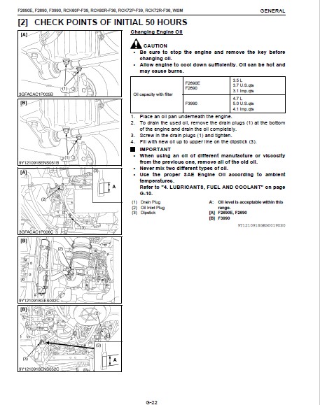
[2] CHECK POINTS OF INITIAL 50 HOURS……………………………… 45
[3] CHECK POINTS OF EVERY 50 HOURS……………………………….. 47
[4] CHECK POINTS OF EVERY 100 HOURS………………………………. 51
[5] CHECK POINTS OF EVERY 200 HOURS………………………………. 56
[6] CHECK POINTS OF EVERY 400 HOURS………………………………. 58
[7] CHECK POINT OF EVERY 800 HOURS……………………………….. 60
[8] CHECK POINT OF EVERY 1500 HOURS………………………………. 60
[9] CHECK POINTS OF EVERY 3000 HOURS……………………………… 60
[10] CHECK POINTS OF EVERY 1 YEAR………………………………… 60
[11] CHECK POINTS OF EVERY 2 YEARS……………………………….. 61
[12] OTHERS……………………………………………………. 63
8. SPECIAL TOOLS…………………………………………………… 66
[1] SPECIAL TOOLS FOR ENGINE…………………………………….. 66
[2] SPECIAL TOOLS FOR MACHINE……………………………………. 75
9. TIRES………………………………………………………….. 76
[1] TIRE PRESSURE………………………………………………. 76
10. IMPLEMENT LIMITATIONS…………………………………………… 77
1 ENGINE…………………………………………………………………. 78
MECHANISM…………………………………………………………….. 79
1. ENGINE BODY…………………………………………………….. 80
[1] CLOSED BREATHER…………………………………………….. 80
[2] HALF-FLOATING HEAD COVER…………………………………….. 80
2. LUBRICATING SYSTEM………………………………………………. 81
3. COOLING SYSTEM………………………………………………….. 82
4. FUEL SYSTEM…………………………………………………….. 83
[1] GOVERNOR [D1105]……………………………………………. 84
[2] ELECTRONIC GOVERNOR [V1505]………………………………….. 86
5. CONSTANT RPM MANAGEMENT CONTROL (F3990 ONLY)……………………….. 87
6. REFORMER AND AFTER TREATMENT DEVICES………………………………. 88
[1] REFORMING MECHANISM…………………………………………. 88
[2] AFTER TREATMENT DEVICES……………………………………… 89
[3] DPF REGENERATION SYSTEM……………………………………… 94
(1) Regeneration Mode……………………………………….. 94
(2) Indicator and Switch Lamp………………………………… 95
(3) PM Warning Level………………………………………… 96
7. ENGINE CONTROL SYSTEM [V1505]…………………………………….. 99
SERVICING……………………………………………………………..100
1. TROUBLESHOOTING………………………………………………….101
2. SERVICING SPECIFICATIONS………………………………………….104
3. TIGHTENING TORQUES……………………………………………….109
4. CHECKING, DISASSEMBLING AND SERVICING………………………………110
[1] CHECKING AND ADJUSTING……………………………………….110
(1) Engine Body……………………………………………..110
(2) Lubricating System……………………………………….112
(3) Cooling System…………………………………………..113
(4) Fuel System……………………………………………..115
(5) Turbocharger (F3990 Only)…………………………………119
[2] DISASSEMBLING AND ASSEMBLING………………………………….120
(1) DPF Muffler (Only F3990)………………………………….120
(2) Separating Engine (F2690E, F2690)………………………….122
(3) Separating Engine (F3990)…………………………………128
(4) External Components (F2690E, F2690)………………………..135
(5) External Components (F3990)……………………………….136
(6) Cylinder Head and Valve…………………………………..137
(7) Oil Pan, Timing Gears, Camshaft and Fuel Camshaft……………142
(8) Piston and Connecting Rod…………………………………147
(9) Crankshaft………………………………………………149
[3] SERVICING…………………………………………………..152
(1) Cylinder Head and Valve…………………………………..152
(2) Timing Gears, Camshaft and Governor Gear……………………157
(3) Piston and Connecting Rod…………………………………160
(4) Crankshaft………………………………………………162
(5) Cylinder………………………………………………..166
(6) Oil Pump………………………………………………..167
2 TRANSMISSION…………………………………………………………….168
MECHANISM……………………………………………………………..169
1. STRUCTURE……………………………………………………….170
[1] FOUR WHEEL DRIVE (F2690, F3990)……………………………….170
[2] TWO WHEEL DRIVE (F2690E)……………………………………..171
2. POWER TRAIN……………………………………………………..172
[1] HYDROSTATIC TRANSMISSION (HST)………………………………..172
(1) Structure……………………………………………….172
(2) Oil Flow………………………………………………..173
(3) Operation……………………………………………….175
(4) Charge Relief Valve………………………………………178
(5) Check and High Pressure Relief Valve……………………….178
(6) Control Linkage………………………………………….180
3. RANGE GEAR SHIFT SECTION………………………………………….181
[1] F2690E, F2690……………………………………………….181
[2] F3990………………………………………………………181
4. REAR WHEEL DRIVE SECTION (ONLY 4WD MODEL)…………………………..182
[1] DUAL-ACTING OVERRUNNING FOUR WHEEL DRIVE……………………….182
(1) Basic Actions in Dual-Acting Overrunning 4WD Mode……………184
(2) Basic Actions in Full-Time 4WD Mode………………………..185
5. PTO SECTION……………………………………………………..186
6. DIFFERENTIAL GEAR SECTION…………………………………………188
[1] DIFFERENTIAL FUNCTION………………………………………..188
[2] DIFFERENTIAL LOCK……………………………………………189
SERVICING……………………………………………………………..190
1. TROUBLESHOOTING………………………………………………….191
2. SERVICING SPECIFICATIONS………………………………………….194
3. TIGHTENING TORQUES……………………………………………….196
4. CHECKING, DISASSEMBLING AND SERVICING………………………………197
[1] CHECKING AND ADJUSTING……………………………………….197
[2] PREPARATION…………………………………………………200
(1) Separating Transmission Assembly…………………………..200
(2) Separating Hydrostatic Transmission (HST)…………………..212
(3) Separating Transmission Case………………………………213
(4) Separating Differential Gear Case………………………….214
[3] DISASSEMBLING AND ASSEMBLING………………………………….215
(1) Hydrostatic Transmission………………………………….215
(2) Hydraulic PTO Clutch Assembly……………………………..217
(3) RWD Case………………………………………………..217
(4) Transmission Case………………………………………..219
(5) Differential Gear Case……………………………………219
[4] SERVICING…………………………………………………..221
(1) Hydrostatic Transmission………………………………….221
(2) Hydraulic PTO Clutch……………………………………..223
(3) Transmission Case………………………………………..224
(4) Differential Gear Case……………………………………225
3 FRONT AXLE………………………………………………………………227
MECHANISM……………………………………………………………..228
1. STRUCTURE……………………………………………………….229
SERVICING……………………………………………………………..230
1. TROUBLESHOOTING………………………………………………….231
2. TIGHTENING TORQUES……………………………………………….232
3. CHECKING, DISASSEMBLING AND SERVICING………………………………233
[1] PREPARATION…………………………………………………233
[2] DISASSEMBLING AND ASSEMBLING………………………………….234
4 BRAKES………………………………………………………………….235
MECHANISM……………………………………………………………..236
1. STRUCTURE……………………………………………………….237
2. OPERATION……………………………………………………….238
SERVICING……………………………………………………………..239
1. TROUBLESHOOTING………………………………………………….240
2. SERVICING SPECIFICATIONS………………………………………….241
3. TIGHTENING TORQUES……………………………………………….242
4. CHECKING, DISASSEMBLING AND SERVICING………………………………243
[1] CHECKING AND ADJUSTING……………………………………….243
[2] DISASSEMBLING AND ASSEMBLING………………………………….244
(1) Brake Pedal……………………………………………..244
(2) Brake Assembly…………………………………………..245
[3] SERVICING…………………………………………………..247
5 REAR AXLE……………………………………………………………….249
MECHANISM……………………………………………………………..250
1. STRUCTURE……………………………………………………….251
[1] FOUR WHEEL DRIVE MODEL (F2690, F3990)………………………….251
[2] TWO WHEEL DRIVE MODEL (F2690E)………………………………..252
SERVICING……………………………………………………………..253
1. TROUBLESHOOTING………………………………………………….254
2. SERVICING SPECIFICATIONS………………………………………….255
3. TIGHTENING TORQUES……………………………………………….257
4. CHECKING, DISASSEMBLING AND SERVICING………………………………258
[1] CHECKING AND ADJUSTING……………………………………….258
[2] PREPARATION…………………………………………………259
(1) Separating Rear Axle [4WD Model (F2690, F3990)]……………..259
(2) Separating Rear Axle [2WD Model (F2690E)]…………………..262
[3] DISASSEMBLING AND ASSEMBLING………………………………….263
(1) 4WD Model (F2690, F3990)………………………………….263
(2) 2WD Model (F2690E)……………………………………….266
[4] SERVICING…………………………………………………..266
(1) 4WD Model (F2690, F3990)………………………………….266
(2) 2WD Model (F2690E)……………………………………….269
6 STEERING………………………………………………………………..270
MECHANISM……………………………………………………………..271
1. STRUCTURE……………………………………………………….272
[1] F2690E, F2690……………………………………………….272
[2] F3990………………………………………………………273
2. STEERING CONTROLLER………………………………………………274
SERVICING……………………………………………………………..275
1. TROUBLESHOOTING………………………………………………….276
2. SERVICING SPECIFICATIONS………………………………………….277
3. TIGHTENING TORQUES……………………………………………….278
4. CHECKING, DISASSEMBLING AND SERVICING………………………………279
[1] CHECKING AND ADJUSTING……………………………………….279
(1) Relief Valve…………………………………………….279
[2] DISASSEMBLING AND ASSEMBLING………………………………….279
(1) Separating Power Steering Controller……………………….279
(2) Separating Steering Support……………………………….282
(3) Steering Shaft…………………………………………..283
[3] SERVICING…………………………………………………..283
(1) Steering Cylinder………………………………………..283
7 HYDRAULIC SYSTEM…………………………………………………………284
MECHANISM……………………………………………………………..285
1. HYDRAULIC CIRCUIT………………………………………………..286
[1] F2690E, F2690……………………………………………….286
[2] F3990………………………………………………………287
2. HYDRAULIC PUMP…………………………………………………..288
[1] F2690E, F2690……………………………………………….288
[2] F3990………………………………………………………289
3. FLOW PRIORITY VALVE (F2690E, F2690)………………………………..290
4. RELIEF VALVE…………………………………………………….291
5. IMPLEMENT CONTROL VALVE…………………………………………..292
6. FEEDBACK LINKAGE…………………………………………………293
7. CYLINDER SAFETY VALVE (F3990)……………………………………..294
8. HYDRAULIC CYLINDER……………………………………………….295
[1] F2690E, F2690……………………………………………….295
[2] F3990………………………………………………………296
SERVICING……………………………………………………………..297
1. TROUBLESHOOTING………………………………………………….298
2. SERVICING SPECIFICATIONS………………………………………….299
3. TIGHTENING TORQUES……………………………………………….301
4. CHECKING, DISASSEMBLING AND SERVICING………………………………302
[1] CHECKING AND ADJUSTING……………………………………….302
(1) Hydraulic Pump and Flow Priority Valve (F2690E, F2690)……….302
(2) Hydraulic Pump (F3990)……………………………………304
(3) Hydraulic Cylinder Assembly……………………………….306
[2] DISASSEMBLING AND ASSEMBLING………………………………….307
(1) Hydraulic Pump and Flow Priority Valve (F2690E, F2690)……….307
(2) Hydraulic Pump (F3990)……………………………………308
(3) Hydraulic Cylinder Assembly……………………………….308
[3] SERVICING…………………………………………………..311
(1) Hydraulic Pump (F2690E, F2690)…………………………….311
(2) Hydraulic Pump (F3990)……………………………………312
(3) Hydraulic Cylinder……………………………………….313
(4) Cylinder Safety Valve (F3990)……………………………..314
8 ELECTRICAL SYSTEM………………………………………………………..315
MECHANISM……………………………………………………………..316
1. WIRING DIAGRAM…………………………………………………..317
[1] F2690E, F2690……………………………………………….317
[2] F3990………………………………………………………318
2. STARTING SYSTEM………………………………………………….319
[1] OPERATOR PRESENCE CONTROL (OPC) SYSTEM…………………………319
(1) Electrical Circuit (F2690E, F2690)…………………………319
(2) Electrical Circuit (F3990)………………………………..320
(3) Related Switches and Controller……………………………320
(4) Operation (F2690E, F2690)…………………………………322
(5) Operation (F3990)………………………………………..324
3. METER PANEL……………………………………………………..326
[1] EASY CHECKER™……………………………………………….326
[2] SERVICE CODE DISPLAY…………………………………………327
[3] ERROR CODE DISPLAY…………………………………………..328
SERVICING……………………………………………………………..329
1. TROUBLESHOOTING………………………………………………….331
2. SERVICING SPECIFICATIONS………………………………………….334
3. TIGHTENING TORQUES……………………………………………….335
4. CHECKING AND ADJUSTING……………………………………………336
[1] BATTERY…………………………………………………….336
[2] GROUNDING…………………………………………………..337
[3] FUSE……………………………………………………….338
[4] RELAY………………………………………………………339
[5] METER PANEL, OPC CONTROLLER AND ENGINE ECU……………………..341
(1) Meter Panel……………………………………………..341
(2) OPC Controller (F2690E, F2690)…………………………….344
(3) Engine ECU (F3990)……………………………………….345
[6] STARTING SYSTEM……………………………………………..348
(1) Main Switch……………………………………………..348
(2) Safety Switch……………………………………………349
(3) Starter…………………………………………………350
(4) Fuel Pump……………………………………………….351
(5) Engine Stop Solenoid (F2690E, F2690)……………………….352
(6) Glow Plug……………………………………………….353
[7] ENGINE CONTROL SYSTEM (F3990)…………………………………354
(1) Throttle Lever Sensor…………………………………….354
(2) Governor Solenoid………………………………………..355
(3) Rack Position Sensor……………………………………..356
(4) Engine Speed Sensor (F3990)……………………………….357
(5) Temperature Sensor (After Treatment System)…………………358
(6) Differential Pressure Sensor………………………………359
(7) Doser Fuel Pump………………………………………….360
(8) Blower Motor…………………………………………….361
(9) Air Valve……………………………………………….362
(10) Blower Flow Pressure Sensor………………………………363
(11) Heater Glow…………………………………………….364
(12) Burner Glow…………………………………………….365
(13) Auto Regeneration Switch…………………………………366
(14) Parked Regeneration Switch……………………………….367
[8] CHARGING SYSTEM……………………………………………..368
(1) Alternator………………………………………………368
[9] LIGHTING SYSTEM……………………………………………..369
(1) Head Light Switch………………………………………..369
[10] INDICATOR ON THE METER PANEL…………………………………370
(1) Engine Speed Sensor (F2690E, F2690)………………………..370
(2) Engine Oil Pressure Switch………………………………..371
(3) Coolant Temperature Sensor………………………………..372
(4) Fuel Sensor……………………………………………..373
(5) 4WD Lock Lever Switch (4WD Model Only)……………………..374
5. DISASSEMBLING AND ASSEMBLING………………………………………375
[1] STARTER…………………………………………………….375
[2] ALTERNATOR………………………………………………….376
6. SERVICING……………………………………………………….378
[1] STARTER…………………………………………………….378
[2] ALTERNATOR………………………………………………….380
9 MOWER…………………………………………………………………..382
GENERAL……………………………………………………………….383
1. MOWER IDENTIFICATION……………………………………………..384
2. GENERAL PRECAUTION……………………………………………….385
3. LUBRICANT……………………………………………………….386
4. TIGHTENING TORQUES……………………………………………….387
[1] GENERAL USE SCREWS, BOLT AND NUTS……………………………..387
[2] METRIC SCREWS, BOLTS AND NUTS…………………………………387
[3] AMERICAN STANDARD SCREWS, BOLTS AND NUTS WITH UNC OR UNF THREADS….388
[4] PLUGS………………………………………………………388
5. MAINTENANCE CHECK LIST……………………………………………389
6. CHECK AND MAINTENANCE…………………………………………….390
[1] CHECK POINTS OF DAILY OF EACH USE……………………………..390
[2] CHECK POINTS OF INITIAL 50 HOURS………………………………392
[3] CHECK POINTS OF EVERY 50 HOURS………………………………..392
[4] CHECK POINT OF EVERY 150 HOURS………………………………..393
[5] CHECK POINT OF EVERY 2 YEARS………………………………….394
MECHANISM……………………………………………………………..395
1. POWER TRANSMISSION……………………………………………….396
SERVICING……………………………………………………………..397
1. TROUBLESHOOTING………………………………………………….398
2. SERVICING SPECIFICATIONS………………………………………….400
3. TIGHTENING TORQUES……………………………………………….401
4. CHECKING, DISASSEMBLING AND ASSEMBLING……………………………..402
[1] CHECKING AND ADJUSTING……………………………………….402
[2] PREPARATION…………………………………………………406
(1) Mower Tilt Up……………………………………………406
(2) Dismounting Mower………………………………………..407
[3] DISASSEMBLING AND ASSEMBLING………………………………….408
[4] SERVICING…………………………………………………..411
IMAGES PREVIEW OF THE MANUAL:

VIDEO PREVIEW OF THE MANUAL:

PLEASE NOTE:
- This is the SAME MANUAL used by the dealerships to diagnose your vehicle
- No waiting for couriers / posts as this is a PDF manual and you can download it within 2 minutes time once you make the payment.
- Your payment is all safe and the delivery of the manual is INSTANT – You will be taken to the DOWNLOAD PAGE.
- So have no hesitations whatsoever and write to us about any queries you may have : heydownloadss @gmail.com
S.V