

KOMATSU PC3000-1E EXCAVATOR HYDRAULIC MINING SHOVEL OPERATION & MAINTENANCE MANUAL 06251 – PDF DOWNLOAD
IMAGES PREVIEW OF THE MANUAL:

DESCRIPTION:
KOMATSU PC3000-1E EXCAVATOR HYDRAULIC MINING SHOVEL OPERATION & MAINTENANCE MANUAL 06251 – PDF DOWNLOAD
DESIGNATED USE OF THE SHOVEL:
- This machine has been manufactured in accordance with advanced and up-to-date technology standards including recognized safety rules. Nevertheless, its use may constitute a risk to life and limb of the user or of third parties, or cause damage to the machine and to other material property.
- The machine must only be used in technically perfect condition in accordance with its designated use and the instructions set out in the operation manual. Only trained safety-conscious operators who are fully aware of the risks involved should operate the machine. Any functional disorders, especially those affecting the safety of the machine, should, therefore, be rectified immediately.
- The hydraulic Shovel is designed exclusively for excavating, i.e. excavation of bulk material and natural soil structure (e.g. earth, clay, sand and stones ashore and off-shore). Observe local and national safety regulations. Special conditions at the worksite require additional safe working precautions, follow your company’s safety instructions. Short traveling distances for changing the working site are considered as part of the designated use of the Shovel.
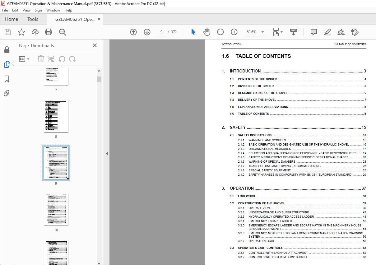
TABLE OF CONTENTS:
KOMATSU PC3000-1E EXCAVATOR HYDRAULIC MINING SHOVEL OPERATION & MAINTENANCE MANUAL 06251 – PDF DOWNLOAD
COVER 1
1 INTRODUCTION 3
1 1 CONTENTS OF THE BINDER 4
1 2 DIVISION OF THE BINDER 5
1 3 DESIGNATED USE OF THE SHOVEL 6
1 4 DELIVERY OF THE SHOVEL 7
1 5 EXPLANATION OF ABBREVIATIONS 8
1 6 TABLE OF CONTENTS 9
2 SAFETY 15
2 1 SAFETY INSTRUCTIONS 16
2 1 1 WARNINGS AND SYMBOLS 16
2 1 2 BASIC OPERATION AND DESIGNATED USE OF THE HYDRAULIC SHOVEL 16
2 1 3 ORGANIZATIONAL MEASURES 17
2 1 4 SELECTION AND QUALIFICATION OF PERSONNEL – BASIC RESPONSIBILITIES 19
2 1 5 SAFETY INSTRUCTIONS GOVERNING SPECIFIC OPERATIONAL PHASES 20
2 1 6 WARNING OF SPECIAL DANGERS 23
2 1 7 TRANSPORTING AND TOWING -RECOMMISSIONING 25
2 1 8 SPECIAL SAFETY EQUIPMENT 25
2 1 9 SAFETY HARNESS IN CONFORMITY WITH EN 361 (EUROPEAN STANDARD) 29
3 OPERATION 37
3 1 FOREWORD 38
3 2 CONSTRUCTION OF THE SHOVEL 39
3 2 1 OVERALL VIEW 39
3 2 2 UNDERCARRIAGE AND SUPERSTRUCTURE 40
3 2 3 HYDRAULICALLY OPERATED ACCESS LADDER 46
3 2 4 EMERGENCY ESCAPE LADDER 50
1 Remove hooks (3) with ladder (2) from bracket (4), see view A, detail (D) 51
2 Take out ladder package from hooks (3) and fasten hooks onto the railing, see view B, detail (E) 51
3 Remove clamp from ladder package (2) and lower the ladder to the ground, see view C 51
4 Use the rope ladder for leaving the Excavator 51
3 2 5 EMERGENCY ESCAPE LADDER AND ESCAPE HATCH IN THE MACHINERY HOUSE (SPECIAL EQUIPMENT) 52
1 Disengage toggle (3) 53
2 Open the hatch (2) and get up on the upper deck 53
3 Depending on the situation, use the emergency escape ladder at the operator’s cab or the normal ground access ladder for leaving the shovel 53
3 2 6 EMERGENCY MOTOR SHUTDOWN FROM GROUND MAN OR OPERATOR WARNING SYSTEM 54
3 2 7 OPERATOR’S CAB 56
3 3 OPERATOR’S CAB – CONTROLS 60
3 3 1 CONTROLS WITH BACKHOE ATTACHMENT 60
3 3 2 CONTROLS WITH BOTTOM DUMP BUCKET 64
3 3 3 OPERATOR’S CONSOLE 68
3 4 ELECTRONIC TEXT MONITORING SYSTEM ETM 74
3 4 1 INTRODUCTION 75
1 FAULT MESSAGES Fault messages indicate a trouble condition, e g Low idle: High pressure filter 1 restricted 75
2 INFORMATION MESSAGES An information message indicates an operating condition, e g # Caution: Slew gear brake on 75
3 4 2 SYSTEM COMPONENTS 79
3 4 3 FUNCTIONS OF THE ETM SYSTEM 81
3 4 4 SEVERAL MESSAGE CONDITIONS OCCUR AT THE SAME TIME 99
3 4 5 SETTINGS OF THE TEXT DISPLAY UNIT (Z 20919) 101
3 5 MACHINERY HOUSE 116
3 6 ELECTRICAL SWITCH CABINET 122
3 6 1 High Voltage switch cabinet, Illust (Z 25367) 123
3 6 2 Medium Voltage Switch Cabinet, illust (Z 25369) 125
1 Main transformer temperature too high 127
2 Wrong direction of rotation 127
3 Over current Motor 127
4 Reserve 127
5 Reserve 127
6 Motor winding temperature too high, Trip 127
7 Reserve 127
8 Insulation monitoring 127
1 Restart lock after voltage failure 127
2 Reserve 127
3 Temperature in medium voltage switch cabinet too high 127
4 Temperature in high voltage switch cabinet too high 127
5 Motor bearing temperature too high, Trip 127
6 Reserve 127
7 Reserve 127
8 Reserve 127
3 7 CHECKS BEFORE STARTING THE MAIN MOTOR 130
3 8 STARTING THE MAIN DRIVE MOTOR 134
1 Lowest permissible starting temperature (ambient temperature): -20° C, see column “1” 141
2 Operating temperature: min + 8° C max + 55° C, see column”2” 141
3 9 STOPPING THE MAIN DRIVE MOTORS 142
1 P a r k t h e Excavator at a safe place on level and solid ground Observe the instructions in section 8 0 “PARKING THE EXCAVATOR“ 142
2 Lower the working attachment onto the ground, proceed as follows: 143
3 Move all controls into neutral position 143
4 Turn stop switch (8) to the right for stopping the motor After the motor has come to a standstill, relieve the pressure in the hydraulic system 143
5 Set main switch key (23) to “0” position and remove 145
3 10 MOVING THE EXCAVATOR 146
3 10 1 Travel Control With Foot Pedals 147
3 10 2 TRAVELLING INSTRUCTIONS 151
3 11 SLEWING AND BRAKING THE SUPERSTRUCTURE 152
3 11 1 SLEWING THE SUPERSTRUCTURE 153
3 12 WORKING WITH THE ATTACHMENT 156
3 12 1 MACHINES EQUIPPED WITH”EURO” CONTROL SYSTEM 156
3 12 2 MACHINES EQUIPPED WITH”KMG” CONTROL SYSTEM 157
3 12 3 BOTTOM DUMP BUCKET 158
3 12 4 DROP BALL OPERATION 159
3 12 5 COMBINED OPERATION CYCLES 162
3 13 WORKING INSTRUCTIONS 164
3 13 1 STABILITY OF THE SHOVEL 164
3 13 2 SHOVEL OPERATION 164
3 14 PARKING THE SHOVEL 167
3 15 OPERATING THE HEATER, VENTILATION AND AIR CONDITIONING 168
3 15 1 Air conditioning (special equipment, illust ( Z 20423) 171
1 If the excavator has been exposed to the sun for a long period it is recommended to ventilate the cab thoroughly by opening doors or windows until the hot air is expelled 171
2 The air conditioner should be operated at least 30 minutes once a month This operation will keep seals from drying out, causing possible damage to the compressor and / or system due to loss of refrigerant For more information, refer to the separ 171
3 The blower switch (8) for cab overpressure should be in position “0” Otherwise too much hot air will be sucked into the operator’s cab 171
3 16 OPERATION OF THE LUBRICATION SYSTEM 172
3 17 FIRE DETECTION AND SUPPRESSION SYSTEM 181
3 18 CENTRAL REFILLING SYSTEM 189
3 18 1 Refilling system for hydraulic oil reservoir, grease barrels of the central lubrication system and slew ring gear lubrication system 190
3 18 2 Refilling procedure 192
3 18 3 Refilling the grease containers of the automatic lubrication system 194
3 19 WORK ON THE LOADER ATTACHMENT 195
3 20 TRANSPORTATION AND LIFTING OF THE SHOVEL 196
3 20 1 DISASSEMBLING OF THE SHOVEL 196
3 20 2 TRANSPORTATION AND LIFTING 196
3 21 RETRIEVAL PROCEDURE 197
3 22 SHOVEL STORAGE 198
3 22 1 PREPARING FOR STORAGE 198
1 Clean the Shovel thoroughly, lubricate all points according to the lubrication chart Move the machine to a protected place or cover the Shovel with a tarpaulin Retract all hydraulic cylinders as far as possible Cover the protruding piston rods 198
2 Refer to Motor Operation and Maintenance Manual for motor storage procedure 198
3 Seal the electrical components and breather on the hydraulic oil reservoir to prevent dirt and moisture from entering 198
4 Remove the batteries and store them in a cool, dry place (0 to 10° C) to minimize self discharge Be sure the batteries are fully charged Never allow batteries to run down below ¾ full charge 198
5 Loosen all drive belts 198
6 Repaint areas that have paint damage with a good quality paint Grease all machined unpainted surfaces with good quality grease to prevent rust 198
7 Drain condensation from hydraulic oil reservoir If necessary, add hydraulic oil 198
8 Attach a tag to the instrument panel to indicate what work has been done 198
3 22 2 ONE MONTH REPETITIVE SERVICE PERIOD 198
1 Service the motor according to the motor manual 198
2 Check all oil levels according to the lubrication chart 198
3 Drain condensation from hydraulic oil reservoir 198
4 Operate air conditioning for approx ½ hour 198
3 22 3 SIX MONTH REPETITIVE SERVICE PERIOD 199
1 Perform steps 1 through 4 of the one month repetitive service period 199
2 Lubricate the Shovel according to lubrication chart (manual lubrication only) 199
3 Check hydraulic system and all gear boxes for leakage If necessary – fill up the units with the specified lubricant Repaint surfaces that have paint damage 199
4 Prepare the motor for operation according to the motor manual Tighten all drive belts Install fully charged batteries Make sure the correct voltage is applied 199
5 Remove coverings from electrical components and breathers on the hydraulic reservoir 199
6 Start the motors 199
7 Operate heater unit and air conditioning 199
8 Operate the central lubricating system and swing ring gear lubrication system Check the lubrication results at the respective lubrication points 199
9 Carry out several complete working cycles with the loader attachment 199
10 Stop the motors Install all coverings which have been removed according to step 5 Service the motor according to the motor manual Lubricate all machined surfaces Remove Batteries and store as described under “Preparing for Storage” Loosen al 199
3 22 4 PREPARING FOR OPERATION 199
1 Remove grease from all machined unpainted surfaces (piston rods) 199
2 Install fully charged batteries 199
3 Remove all coverings 199
4 Service the motor according to the motor manual Tighten all drive belts 199
5 Carry out the maintenance according to the maintenance section 4 in this manual 199
6 Start the motors DO NOT place the Shovel under load before the normal operating values are indicated 199
7 Carry out several complete working cycles Check the function of special equipments (central lubricating system, swing circle pinion lubricating system, fire detection and suppression system etc ) 199
3 23 TROUBLE SHOOTING 200
3 23 1 MAIN DRIVE ELECTRIC MOTOR 200
3 23 2 HYDRAULIC SYSTEM 201
3 23 3 FINAL DRIVES AND SWING GEAR 202
3 23 4 CRAWLER TRACKS 202
4 MAINTENANCE 203
4 1 FOREWORD 204
4 2 PRECAUTIONS FOR MAINTENANCE 205
4 3 FLUIDS AND LUBRICANTS 207
4 3 1 LUBRICANTS FOR OPERATION IN COLD AND ARCTIC CLIMATES 207
4 3 2 FLUIDS AND LUBRICANTS FOR MODERATE AND HOT CLIMATES 208
4 3 3 MAIN DRIVE ELECTRIC MOTORS – BEARING LUBRICATION 209
4 4 FILLING CAPACITIES 212
4 5 STANDARD TORQUE LIST 213
4 6 LUBRICATION AND MAINTENANCE SCHEDULE 214
4 6 1 INITIAL SERVICING 214
4 6 2 PERIODIC SERVICING INTERVALS 214
4 6 3 PERIODIC SERVICING SCHEDULE 215
4 6 4 MAINTENANCE OF THE MAIN DRIVE MOTORS 218
4 6 5 REPLACEMENT OF HYDRAULIC HOSE LINES 220
4 6 6 PERIODIC REPLACEMENT OF SAFETY CRITICAL PARTS 221
4 7 WHEN NECESSARY 224
4 7 1 SWING CIRCLE TOOTHING LUBRICATION 225
4 7 2 AUTOMATIC LUBRICATION SYSTEMS FILL GREASE CONTAINERS 227
1 Screw off filter case 229
2 Remove element assy (02) and clean Take care not to contaminate the ”Clean” inside of the element when flushing 229
3 Inspect O-rings (03 and 05) and back-up ring (04) Replace if necessary 229
4 Fill filter case half way up with the specified grease 229
5 Installation sequence vice versa Take care for proper position of filter element (02) 229
4 7 3 TRACK ROLLERS AND GUIDE WHEELS – REPLACE FLOATING SEALS 231
4 8 EVERY 10 OPERATING HOURS OR DAILY 232
4 8 1 WALK – AROUND INSPECTION 233
1 Check to make sure grease supply through inlet line is provided 239
2 Disconnect the outlet line of the respective injector 239
3 Operate the central lubrication system manually 239
4 Operate the central lubrication system and re-check operation of the grease injectors 239
4 8 2 Cleaning the track group, illust (Z 9550) 243
4 9 EVERY 50 OPERATING HOURS OR WEEKLY 244
4 9 1 SWING GEAR AND MOTOR ADAPTER HOUSING – CHECK OIL LEVEL 245
4 9 2 TRAVEL GEARS, BRAKE HOUSINGS AND MOTOR ADAPTER HOUSINGS – CHECK OIL LEVELS 247
4 9 3 PTO (PUMP DISTRIBUTOR GEAR) – CHECK OIL LEVEL 251
1 Unscrew level gauge (1) and wipe it clean 251
2 Insert gauge (1), but DO NOT screw in, see detail (A) 251
3 Remove level gauge and read the oil level The oil level should be between the “MIN” and “MAX” mark If necessary, add oil through filler opening (2) up to the “MAX” mark on gauge (1) 251
4 Insert gauge (1) and tighten securely Remove breather filter (3) Blow out with compressed air from inside to outside and reinstall 251
1 Unscrew level gauge (8), illustration Z 20837 and wipe it clean 253
2 Insert gauge (8), but DO NOT screw in, see detail (A) 253
3 Remove level gauge and read the oil level The oil level should be between the “MIN” and “MAX” mark If necessary, add oil through filler opening (A) up to the “MAX” mark on gauge (8) 253
4 Blow out breather filter with compressed air from inside to outside Insert gauge (8) and tighten securely 253
4 9 4 Hydraulic Oil Cooler, illust (20009) Inspect and clean if necessary: 255
4 9 5 HYDRAULIC ACCESS LADDER – CHECK SAFETY SENSOR 257
4 10 EVERY 250 OPERATING HOURS OR MONTHLY 258
4 10 1 SIGNAL HORN COMPRESSOR – LUBRICATE 259
4 10 2 HYDRAULIC OIL COOLER FAN BEARINGS – CHECK FOR LEAKAGE AND CLEAN BREATHER FILTER 259
4 10 3 AUTOMATIC LUBRICATION SYSTEMS – CLEAN IN-LINE GREASE FILTER AND CHECK BREATHER FILTER 261
1 Unscrew plug (18), illustration Z 21465, using 36 mm width wrench and remove packing ring (19) 263
2 Take out spring (21), spring guide (22) and element (12) 263
3 Clean all parts and inspect for damage Replace as necessary 263
4 Assemble all parts according to the illustration Make sure all sealing surfaces are clean Take care for proper position of spring guide (22) 263
5 Install plug screw (18) with new packing ring (19) and tighten with a wrench 263
4 10 4 CAB AIR CLEANER – CLEAN OR REPLACE FILTER ELEMENT 265
1 Remove air cleaner housing (1) 265
2 Remove and inspect element (2) If any rupture, holes or damaged gaskets are discovered replace the element 265
3 If the element is usable clean with compressed air from inside to outside and re-install 265
4 10 5 WINDSHIELD WASHER RESERVOIR – CHECK FLUID LEVEL 267
4 10 6 AIR CONDITIONING FOR OPERATOR’S CAB – CHECK REFRIGERANT LEVEL 267
4 11 EVERY 500 OPERATING HOURS OR MONTHLY 268
4 11 1 BATTERIES – CHECK FLUID LEVEL 269
1 Remove the two battery main switch keys (1) 269
2 Open floor plates (2) 269
3 Check electrolyte level (4) of batteries (3) 269
4 If necessary remove filler and breather caps and top up with clean distilled water 269
5 See that contact surfaces of battery terminals are bright Clean if necessary and apply some vaseline to the terminal posts 269
4 11 2 CRAWLER TRACK – INSPECTION 271
1 Make sure pressure relief cock (5) illust Z 20371 is in closed position “C”; and shutoff cocks (6 and 9) are in open position “O” 275
2 Start the engine/motor 275
3 Slowly open vent valves (12) on all four adjusting cylinders until bubble free oil flows out Close the vent valves (12) 275
4 Move the machine forward and reverse to distribute tension 275
5 Check adjusting range “X” according to Illust (Z 20015) on previous page 275
6 Check the complete system for leakages 275
4 12 EVERY 1000 OPERATING HOURS OR EVERY 6 MONTH 276
4 12 1 HIGH STRENGTH BOLT CONNECTIONS – CHECK TORQUE LOAD 277
1 Loosen the two measuring bolts (7) at the left crawler carrier and the two measuring bolts at the right crawler carrier Do not lubricate the measuring bolts 301
2 Tighten the four measuring bolts (7) with 150 Nm 301
3 Attach the measuring device (1 – 6) 301
4 Set the dial gauge (2) to the zero position 301
5 Attach the special hydraulic torque wrench (1), see illustration Z24072 on next page to the measuring bolt (7) 301
6 Increase the pressure at the hydraulic torque wrench until a torque of 2100 Nm is reached and tighten the measuring bolt 301
7 Record the pressure and the change of the bolt length in a table 301
8 Increase the pressure further by steps of 10 bar until the required elongation of 0 93 mm of the measuring bolts (7) is reached 301
9 Record the corresponding hydraulic pressures in a table 301
10 Repeat this procedure on all four measuring bolts (7) 301
11 Add the 4 determined hydraulic pressures and then divide by 4 to obtain an average value 301
12 Now loosen one of the mounting bolts (M48) and tighten up to the determined average pressure 301
13 Repeat this procedure at all bolts (M48) step by step 301
4 12 2 HYDRAULIC SYSTEM – FILTER SERVICE 307
1 Remove nut (A) 311
2 Remove cover (B) 311
3 Remove filter element (C) 311
4 Insert new filter element and reassemble the breather filter (2) 311
1 Place working attachment on the ground and shut-off the motor Relieve pressure in the hydraulic system with several movements of the control levers 313
2 Place a suitable container below the filter in order to collect outflowing oil 313
3 Remove plug (7) and drain the oil 313
4 Screw off filter case (8) 313
5 Remove element (10) and clean Take care not to contaminate the “Clean” inside of the element when flushing 315
6 Inspect O-rings (12 and 14) and back-up ring (13) Replace if necessary 315
7 Install drain plug (7) with new packing ring (11) Fill filter case (8) half way up with clean hydraulic oil and re-assemble the filter Make sure element (10) is properly seated in the filter head 315
8 After short operating period check filter units for leakage 315
1 Remove element (F) and clean Take care not to contaminate the “Clean” inside of the element when flushing 319
2 Inspect O-rings (G and D) and back-up ring (E) Replace if necessary 319
3 Install drain plug (A) with new packing ring (B) Fill filter case (C) half way up with clean hydraulic oil and re-assemble the filter Make sure element (F) is properly seated in the filter head 319
4 After short operating period check filter units for leakage 319
4 12 3 Pump Distributor Gears, Slew Gears and Travel Gears 321
4 12 4 SIGNAL HORN COMPRESSOR – CLEAN AND LUBRICATE 323
4 12 5 HYDRAULIC TRACK TENSIONING SYSTEM – CHECK PRESSURE ACCUMULATORS 325
4 12 6 HYDRAULIC OIL COOLER – INSPECT AND LUBRICATE DOOR HINGES 327
4 12 7 MACHINERY HOUSE DOORS – INSPECT AND LUBRICATE DOOR HINGES 327
4 13 EVERY 2000 OPERATING HOURS OR YEARLY 328
4 13 1 HYDRAULIC SYSTEM – CHANGE OIL, REPLACE SUCTION STRAINERS AND PULSATION DAMPER 329
1 Remove plastic cover 333
2 Adjust the temperature limit value at the drum scale use a small screwdriver 333
3 Reinstall the plastic cover 333
4 13 2 EMERGENCY ESCAPE LADDER – INSPECTION 337
4 14 EVERY 3000 OPERATING HOURS HOWEVER AT LEAST ONCE A YEAR 338
4 14 1 SWING GEAR AND MOTOR ADAPTER HOUSING – CHANGE OIL 339
1 Use adequate working platform for draining the oil Place receptacles of sufficient capacity (approx 60 liter) below drain couplings (7) Attach drain hose (part of tool set) to drain coupling (7) Remove parts (1, 2 and 3) to speed up draining 339
2 Clean breather filter (3) with compressed air from inside to outside and re-install 339
3 After the oil is completely drained, flush the gear with the regular gear oil 339
4 Remove drain hose from coupling (7) and attach the protection cap onto the drain coupling 339
5 Fill gear housing through filler opening (2) up to the “MAX” mark on level gauge (1) with fresh oil and re-install plug (2) 339
6 After short operating period check oil level and housing for leaks 339
1 Remove level gauge (4) and breather filter (5) Insert the hose of a suction pump into the gauge pipe (4) until the hose end just touches the bottom of the T-union Place the oil outlet hose of the suction pump into a receptacle Switch on the pum 341
2 Clean breather filter (5) with compressed air from inside to outside and re-install 341
3 If removed, install drain plug (6) and fill-up gear oil through filler opening (4), up to the “MAX” mark on level gauge (4) and install the level gauge 341
4 After short operating period check oil level and housing for leaks 341
1 Use adequate working platform for draining the oil Place receptacles of sufficient capacity (approx 70 liter) below drain coupling (11) Attach drain hose (part of tool set) to drain coupling (11) Remove parts (4 and 10) to speed up draining 343
2 Clean breather filter (10) with compressed air from inside to outside and re-install 343
3 After the oil is completely drained, flush the gear with the regular gear oil 343
4 Remove drain hose from coupling (11) and attach the protection cap onto the drain coupling 343
5 Fill gear housing through filler opening up to the “MAX” mark on level gauge (4) with fresh oil and re-install oil filler plug 343
6 After short operating period check oil level and housing for leaks 343
1 Remove level gauge (8), illustration Z 25963, drain plug (9) and breather filter (7) Drain the oil into a receptacle of approx 5 liter capacity 345
2 Clean breather filter (7) with compressed air from inside to outside and re-install 345
3 Install drain plug (9) and fill-up engine oil SAE 10 or hydraulic oil HLP 32 through filler opening up to the lower mark on level gauge (8) and install the level gauge DO NOT overfill the brake housing, otherwise the brake could be damaged due to 345
4 After short operating period check oil level and housing for leaks 345
1 Remove level gauge (6) and drain plug (5) Drain the oil into a receptacle of approx 5 liter capacity 345
2 Install drain plug (5) and fill-up engine or hydraulic oil through filler opening, up to the “MAX” mark on level gauge (6) and install the level gauge 345
3 After short operating period check oil level and housing for leaks 345
4 14 2 TRAVEL GEARS, BRAKE AND MOTOR ADAPTER HOUSINGS – CHANGE OIL 347
1 Move the Excavator so, that the drain plug (3) is in the lowest and filler plug (2) is in the uppermost position The oil level plug (1) is then correctly positioned 349
2 Place suitable receptacles below drain plugs (3 and 6) 349
3 Remove filler, level and drain plugs (1 – 6) and drain the oil completely into the receptacles 349
4 After the oil is completely drained, flush both gear boxes with the regular gear oil Install drain plugs (3 and 6) 349
5 Fill planetary gear box with specified gear oil through filler opening (2) up to level opening (1) Install plugs (1 and 2) 349
6 Fill spur gear box with specified gear oil through filler opening (5) up to level opening (4) Install plugs (4 and 5) 349
7 Remove breather filter (11) and blow out with compressed air from inside to outside Install breather filter (11) 349
1 Place wedges at front and rear side of both crawlers, start the motor and lower the bucket to the ground 349
2 Have a second person for control in the operator’s cab 349
3 Remove parts (7 to 9) and drain the oil completely 349
4 Shut down the motor 349
5 Install plug (9) and fill in fresh engine or hydraulic oil up to level openings (7) Install plugs (7 and 8) 349
1 Remove plugs (10 to 12) and drain the oil completely 349
2 Install drain plug (12) and fill-up engine or hydraulic oil to level openings (10) Install plugs (10 and 11) 349
4 14 3 PTO (PUMP DISTRIBUTOR GEAR) – CHANGE OIL 351
1 Remove drain plug (4), gauge (1) and filler plug (2) 351
2 Remove breather filter (3), blow out with compressed air from inside to outside and re-install 351
3 After the oil is completely drained, flush the gear with the regular gear oil and reinstall drain plug (4) 351
4 Fill in new oil through opening (2) up to the “MAX” mark on gauge (1) 351
5 Re-install parts (1 and 2) 351
6 Vent the PTO lubrication pump, see page 331 for more information 351
7 After short operating period, check oil level and housing for leakage 351
4 15 FIRE PREVENTION 356
1 Keep the excavator clean, especially from inflammable materials Clean the excavator after servicing the hydraulic system, motor and fuel system by means of a steam jet 357
2 Clean motor compartment, hydraulic pump compartment and service platform of the superstructure Thereafter hydraulic oil lines for leakage, loose fastenings and damage If any leakage, damage or loose fastening is found, corrective action must be 357
3 Check all electrical cables, terminals and connections for loose fastenings, damage and wear Replace or repair defective or worn parts without delay 357
4 Check the turbocharger for correct mounting and tight exhaust, intake and lube oil connections Carry out all necessary repairs without delay 357
5 On machines equipped with a fire detection, actuation and suppression system: Refer to the manufacturers service manuals in volume 2 binder for correct maintenance and inspection of the systems When checking the filling level of the dry chemical 357
6 Make sure fire extinguishers are charged and ready for use 357
4 16 WELD REPAIRS 358
4 16 1 PROTECTIVE MEASURES BEFORE STARTING WELD REPAIRS ON THE UNDERCARRIAGE 361
4 16 2 PROTECTIVE MEASURES BEFORE STARTING WELD REPAIRS ON THE LOADER ATTACHMENT 363
4 16 3 PROTECTIVE MEASURES BEFORE STARTING WELD REPAIRS ON THE SUPERSTRUCTURE 365
1 Switch off all circuit breakers in the switch box (X2) 367
2 Remove the three green plugs from the sockets (X23 and X24) on the master input signal module (E34) Remove the two green plugs from the socket (X26) on the slave input signal module (E39) 367
3 Disconnect all plugs on the back of the multi monitor (E62) 367
4 Remove the wiring harness connector from electronic pump controller CR700 (E61) 367
4 16 4 AFTER FINISHING THE WELD REPAIRS ON THE SUPERSTRUCTURE 367
VIDEO PREVIEW OF THE MANUAL:
PLEASE NOTE:
- This is the SAME exact manual used by your dealers to fix your vehicle.
- The same can be yours in the next 2-3 mins as you will be directed to the download page immediately after paying for the manual.
- Any queries / doubts regarding your purchase, please feel free to contact [email protected]
I.G


