

Komatsu 107E-1 Series Engine Shop Manual SEN00161-28 – PDF DOWNLOAD
IMAGES PREVIEW OF THE MANUAL:


DESCRIPTION:
Komatsu 107E-1 Series Engine Shop Manual SEN00161-28 – PDF DOWNLOAD
How to read the shop manual
1. Composition of shop manual
This shop manual contains the necessary technical information for services performed in a workshop.
For ease of understanding, the manual is divided into the following sections.
00. Index and foreword
This section explains the shop manuals list, table of contents, safety, and basic information.
01. Specification
This section explains the specifications of the machine.
10. Structure, function and maintenance standard
This section explains the structure, function, and maintenance standard values of each component.
The structure and function sub-section explains the structure and function of each component. It
serves not only to give an understanding of the structure, but also serves as reference material for
troubleshooting. The maintenance standard sub-section explains the criteria and remedies for disassembly
and service.
20. Standard value table
This section explains the standard values for new machine and judgement criteria for testing,
adjusting, and troubleshooting. This standard value table is used to check the standard values in
testing and adjusting and to judge parts in troubleshooting.
30. Testing and adjusting
This section explains measuring instruments and measuring methods for testing and adjusting, and
method of adjusting each part. The standard values and judgement criteria for testing and adjusting
are explained in Testing and adjusting.
40. Troubleshooting
This section explains how to find out failed parts and how to repair them. The troubleshooting is
divided by failure modes. The “S mode” of the troubleshooting related to the engine may be also
explained in the Chassis volume and Engine volume. In this case, see the Chassis volume.
50. Disassembly and assembly
This section explains the special tools and procedures for removing, installing, disassembling, and
assembling each component, as well as precautions for them. In addition, tightening torque and
quantity and weight of coating material, oil, grease, and coolant necessary for the work are also
explained.
90. Diagrams and drawings (chassis volume)/Repair and replacement of parts (engine volume)
q Chassis volume
This section gives hydraulic circuit diagrams and electrical circuit diagrams.
q Engine volume
This section explains the method of reproducing, repairing, and replacing parts.
TABLE OF CONTENTS:
Komatsu 107E-1 Series Engine Shop Manual SEN00161-28 – PDF DOWNLOAD
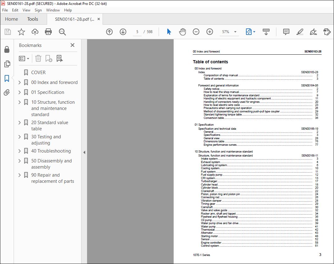
00 Index and foreword
Index SEN00163-28
Composition of shop manual 2
Table of contents 3
Foreword and general information SEN00164-06
Safety notice 2
How to read the shop manual 7
Explanation of terms for maintenance standard 9
Handling of electric equipment and hydraulic component 11
Handling of connectors newly used for engines 20
How to read electric wire code 23
Precautions when carrying out operation 26
Method of disassembling and connecting push-pull type coupler 29
Standard tightening torque table 32
Conversion table 36
01 Specification
Specification and technical data SEN00166-19
General 2
Specifications 3
General view 28
Dimensions table 76
Engine performance curves 77
10 Structure, function and maintenance standard
Structure, function and maintenance standard SEN00168-11
Intake system 3
Exhaust system 4
Lubricating oil system 6
Cooling system 10
Fuel system 11
Fuel supply pump 12
CRI system 13
Turbocharger 17
Cylinder head 18
Cylinder block 20
Crankshaft 22
Piston, piston ring and piston pin 24
Connecting rod 26
Vibration damper 28
Timing gear 29
Camshaft 30
Valve and valve guide 32
Rocker arm, shaft and tappet 34
Flywheel and flywheel housing 36
Oil pump 38
Water pump drive and fan drive 39
Water pump 41
Thermostat 42
Alternator 43
Starting motor 48
Sensor 52
Engine controller 58
Control system 61
SEN00163-28 00 Index and foreword
4 107E-1 Series
20 Standard value table
Standard service value table SEN00248-19
Standard value table for testing, adjusting and troubleshooting 2
Running-in standard and performance test criteria 25
30 Testing and adjusting
Testing and adjusting SEN00250-09
Testing and adjusting tools list 2
Sketches of special tools 4
Testing boost pressure 5
Adjustment of valve clearance 6
Testing compression pressure 9
Testing blowby pressure 12
Testing engine oil pressure 13
Handling fuel system parts 14
Releasing remaining pressure in fuel system 14
Testing fuel pressure 15
Reduced cylinder mode operation 21
No-injection cranking 21
Testing fuel delivery, return and leak amount 22
Bleeding air from fuel circuit 33
Testing fuel system for leakage 34
Handling controller high-voltage circuit 35
Replacing the fan belt 35
40 Troubleshooting
General information on troubleshooting SEN00252-04
Points on troubleshooting 2
Error and failure code table 3
Troubleshooting method for open circuit in wiring harness of pressure sensor system 5
Information in troubleshooting table 7
Connection table for connector pin numbers 9
T- branch box and T- branch adapter table 45
Troubleshooting of electrical system (E-mode), Part 1 SEN00254-04
E-1 Code [111/CA111] Abnormality in engine controller 3
E-2 Code [115/CA115] Abnormality in engine Ne, Bkup speed sensor 3
E-3 Code [122/CA122] Charge pressure sensor high error 4
E-4 Code [123/CA123] Charge pressure sensor low error 6
E-5 Code [131/CA131] Throttle sensor power supply high error 8
E-6 Code [132/CA132] Throttle sensor power supply low error 10
E-7 Code [144/CA144] Coolant temperature sensor high error 12
E-8 Code [145/CA145] Coolant temperature sensor low error 14
E-9 Code [153/CA153] Charge temperature sensor high error 16
E-10 Code [154/CA154] Charge temperature sensor low error 18
E-11 Code [155/CA155] Derating of speed by charge temperature high error 20
E-12 Code [187/CA187] Sensor power supply 2 low error 22
E-13 Code [221/CA221] Atompspheric pressure sensor high error 24
E-14 Code [222/CA222] Atompspheric pressure sensor low error 26
E-15 Code [227/CA227] Sensor power supply 2 high error 28
E-16 Code [234/CA234] Engine overspeed 28
E-17 Code [238/CA238] Abnormallity in Ne speed sensor power supply 29
E-18 Code [271/CA271] Short circuit in IMV/PCV1 30
E-19 Code [272/CA272] Disconnection in IMV/PCV1 32
E-20 Code [322/CA322] Disconnection, short circuit in injector No 1 34
E-21 Code [323/CA323] Disconnection, short circuit in injector No 5 36
E-22 Code [324/CA324] Disconnection, short circuit in injector No 3 38
E-23 Code [325/CA325] Disconnection, short circuit in injector No 6 40
00 Index and foreword SEN00163-28
107E-1 Series 5
E-24 Code [331/CA331] Disconnection, short circuit in injector No 2 42
E-25 Code [332/CA332] Disconnection, short circuit in injector No 4 44
E-26 Code [342/CA342] Calibration error in engine controller data 46
E-27 Code [351/CA351] Abnormality in injector drive circuit 47
E-28 Code [352/CA352] Sensor power supply 1 low error 48
E-29 Code [386/CA386] Sensor power supply 1 high error 50
E-30 Code [428/CA428] Water-in-fuel sensor high error 52
E-31 Code [429/CA429] Water-in-fuel sensor low error 54
E-32 Code [431/CA431] Abnormality in idle validation switch 56
E-33 Code [432/CA432] Abnormality in idle validation processing 58
Troubleshooting of electrical system (E-mode), Part 2 SEN00255-04
E-34 Code [435/CA435] Abnormality in engine oil pressure switch 3
E-35 Code [441/CA441] Abnormally low power supply voltage 4
E-36 Code [442/CA442] Abnormally high power supply voltage 6
E-37 Code [449/CA449] Common rail pressure high error 2 7
E-38 Code [451/CA451] Common rail pressure sensor high error 8
E-39 Code [452/CA452] Common rail pressure sensor low error 10
E-40 Code [488/CA488] Derating of torque by charge temperature high error 12
E-41 Code [553/CA553] Common rail pressure high error 1 12
E-42 Code [559/CA559] No-pressure feed 1 by supply pump 13
E-43 Code [689/CA689] Abnormality in engine Ne speed sensor 15
E-44 Code [731/CA731] Abnormality in engine Bkup speed sensor phase 17
E-45 Code [757/CA757] Loss of all data in engine controller 18
E-46 Code [778/CA778] Abnormality in engine Bkup speed sensor 19
E-47 Code [1633/CA1633] Abnormality in KOMNET 22
E-48 Code [2185/CA2185] Throttle sensor power supply high error 23
E-49 Code [2186/CA2186] Throttle sensor power supply low error 24
E-50 Code [2249/CA2249] No-pressure feed 2 by supply pump 25
E-51 Code [2311/CA2311] Abnormality in IMV solenoid 25
E-52 Code [2555/CA2555] Disconnection in intake air heater relay 26
E-53 Code [2556/CA2556] Short circuit in intake air heater relay 28
E-54 Code [—/B@BAZG] Derating of speed by engine oil pressure reduction 30
E-55 Code [—/B@BAZK] Engine oil level low 30
E-56 Code [—/B@BCNS] Engine overheat 31
E-57 Code [A8] Rated Speed Adjustment Volume (Isochronous) High Error 32
E-58 Code [A9] Rated Speed Adjustment Volume (Isochronous) Low Error 34
E-59 Code [AA] Rated Speed Adjustment Volume (Droop) High Error 36
E-60 Code [AB] Rated Speed Adjustment Volume (Droop) Low Error 38
E-61 Code [AF] Abnormality in KOMNET (CR710 error recognition) 40
E-62 Code [b6] Droop Rate Adjustment Volume High Error 44
E-63 Code [b7] Droop Rate Adjustment Volume Low Error 46
E-64 Code [b8] Low Idle Speed Adjustment Volume High Error 48
E-65 Code [b9] Low Idle Speed Adjustment Volume Low Error 50
E-66 Code [bc] Rated Speed Median Adjustment Volume High Error 52
E-67 Code [b9] Rated Speed Median Adjustment Volume Low Error 54
E-68 Code [bE] Ramp Time Adjustment Volume High Error 56
E-69 Code [bF] Ramp Time Adjustment Volume Low Error 58
Troubleshooting of mechanical system (S-mode) SEN00253-02
Troubleshooting of mechanical system (S-mode) 1
Method of using troubleshooting charts 4
S-1 Starting performance is poor 8
S-2 Engine does not start 9
S-3 Engine does not pick up smoothly 12
S-4 Engine stops during operations 13
S-5 Engine does not rotate smoothly 14
S-6 Engine lacks output (or lacks power) 15
S-7 Exhaust smoke is black (incomplete combustion) 16
S-8 Oil consumption is excessive (or exhaust smoke is blue) 17
SEN00163-28 00 Index and foreword
6 107E-1 Series
S-9 Oil becomes contaminated quickly 18
S-10 Fuel consumption is excessive 19
S-11 Oil is in coolant (or coolant spurts back or coolant level goes down) 20
S-12 Oil pressure drops 21
S-13 Oil level rises (Entry of coolant or fuel) 22
S-14 Coolant temperature becomes too high (overheating) 23
S-15 Abnormal noise is made 24
S-16 Vibration is excessive 25
50 Disassembly and assembly
General information on disassembly and assembly SEN00257-06
How to read this manual 2
Coating materials list 4
Special tools list 7
Disassembly and assembly, Part 1 SEN00258-07
General disassembly of engine 2
Disassembly and assembly, Part 2 SEN00259-10
General assembly of engine 2
90 Repair and replacement of parts
Information related to repair and replacement SEN05211-01
Special tool table 2
Parts related to cylinder head SEN05212-00
Repair of cylinder head 2
Check of valve guide 3
Replacement of valve seat insert 4
Vacuum test of valve seat insert 6
Grinding of valve 7
Parts related to cylinder block SEN05213-01
Repair of cylinder block 2
Repair of crankshaft 14
Replacement of connecting rod bushing 17
VIDEO PREVIEW OF THE MANUAL:
PLEASE NOTE:
- This is the same manual used by the DEALERSHIPS to SERVICE your vehicle.
- The manual can be all yours – Once payment is complete, you will be taken to the download page from where you can download the manual. All in 2-5 minutes time!!
- Need any other service / repair / parts manual, please feel free to contact us at heydownloadss @gmail.com . We may surprise you with a nice offer
S.V


