

Kawasaki Wheel Loader ZX250 7 Operational & Service Manual & Parts Manual
File Details:
Kawasaki Wheel Loader ZX250 7 Operational & Service Manual & Parts Manual
Language : English
Pages : 500+
Size : 206 MB
Downloadable : Yes
Format : PDF
Video Preview:

Image Preview:
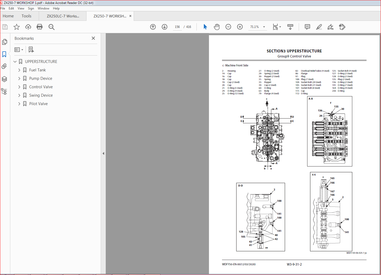
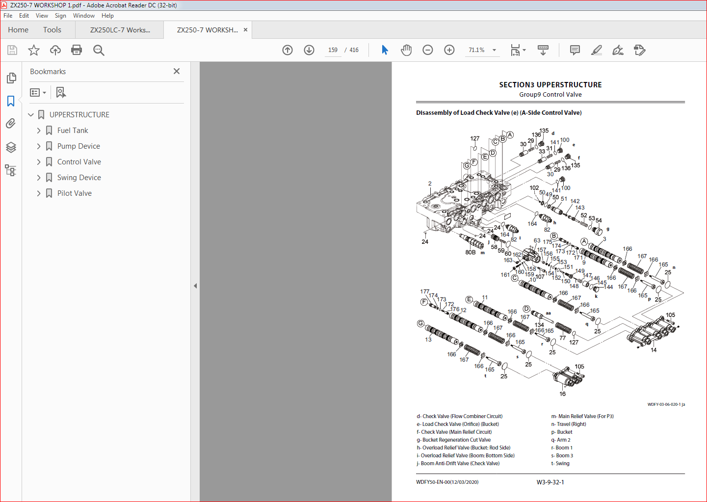
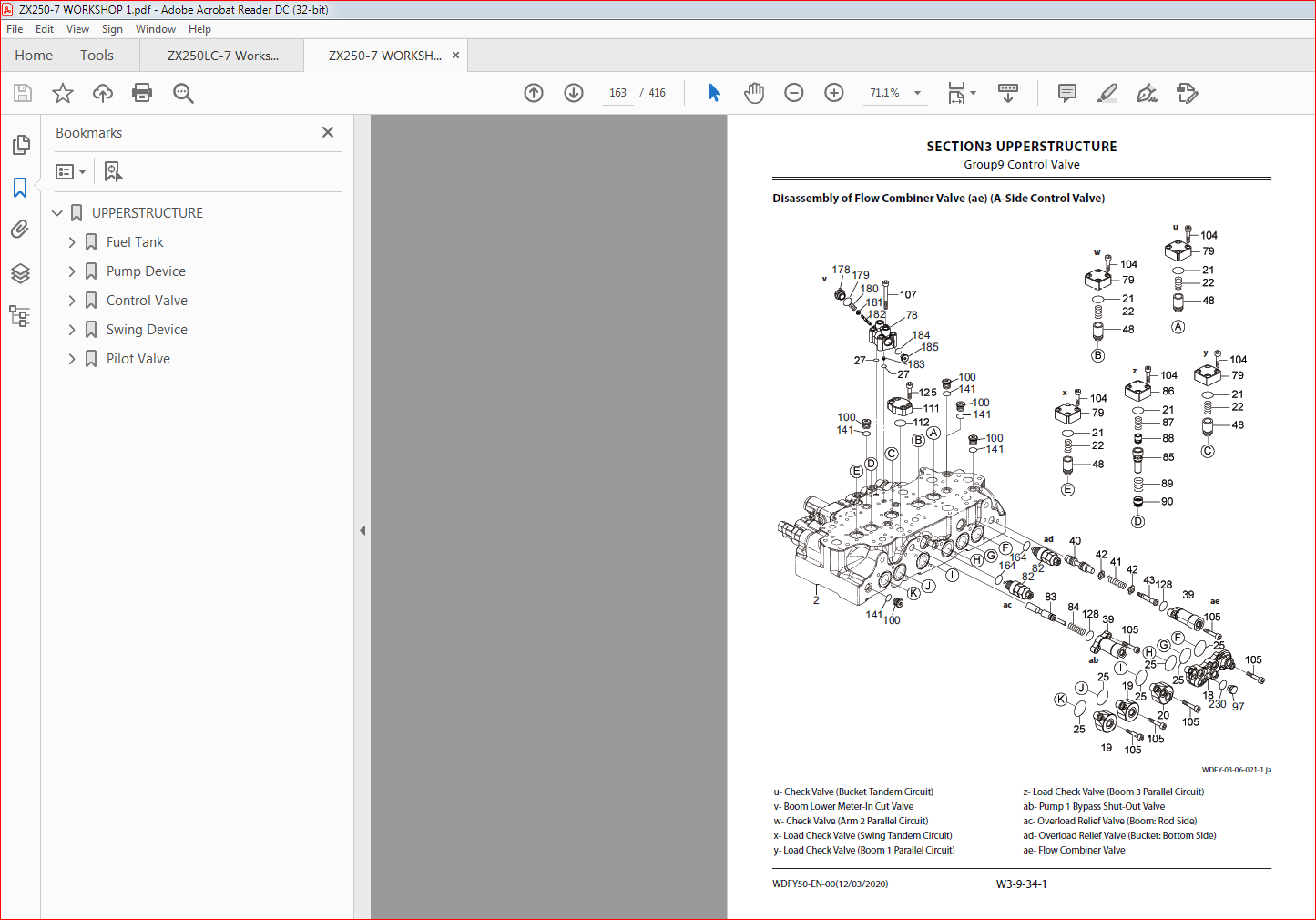
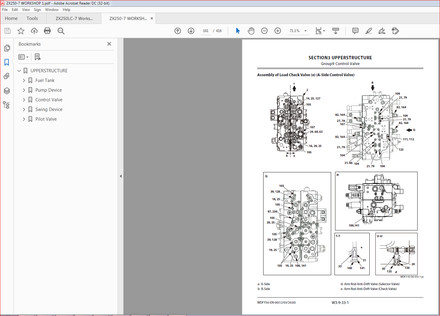
Table of Contents:
Kawasaki Wheel Loader ZX250 7 Operational & Service Manual & Parts Manual
Cab………………………………………………..W3-1-1-1
Removal of Cab Interior Parts……………………………….W3-1-1-1
Removal of Cab Exterior Parts………………………………W3-1-2-1
Removal of Cab Body…………………………………………….W3-1-3-1
Removal of Controller Assembly and Parts Around the Monitor…………………………………………………………W3-1-4-1
Installation of Controller Assembly and Parts Around the Monitor………………………………………….W3-1-5-1
Installation of Cab Body………………………………………..W3-1-6-1
Installation of Cab Exterior Parts………………………….W3-1-7-1
Installation of Cab Interior Parts…………………………..W3-1-8-1
Dimensions of Cab Glass……………………………………….W3-1-9-1
Procedure to Remove Cab Glass……………………….W3-1-10-1
Procedure to Install Cab Glass……………………………W3-1-11-1
Procedures to Install Upper Door Glass……………W3-1-12-1
Procedures to Install Upper Front Glass…………..W3-1-13-1
Counterweight……………………………….W3-2-1-1
Removal of Counterweight…………………………………..W3-2-1-1
Installation of Counterweight………………………………W3-2-2-1
Main Frame……………………………………W3-3-1-1
Removal of Main Frame…………………………………………W3-3-1-1
Installation of Main Frame…………………………………….W3-3-2-1
Engine……………………………………………W3-4-1-1
Preparation before Removal of Engine……………….W3-4-1-1
Removal of Covers and Related Parts Around the Engine………………………………………………………………….W3-4-2-1
Removal of Wire Harnesses and Hoses Around the Engine………………………………………………………………….W3-4-3-1
Removal of Engine Body……………………………………….W3-4-4-1
Installation of Engine Body…………………………………..W3-4-5-1
Installation of Wire Harnesses and Hoses Around the Engine…………………………………………………………..W3-4-6-1
Installation of Related Parts of the Engine…………W3-4-7-1
Work after Installation of Engine and Installation of Covers……………………………………………………………..W3-4-8-1
Radiator Assembly…………………………W3-5-1-1
Removal of Radiator………………………………………………W3-5-1-1
Installation of Radiator…………………………………………..W3-5-2-1
Removal of Intercooler………………………………………….W3-5-3-1
Installation of Intercooler………………………………………W3-5-4-1
Removal of Oil Cooler…………………………………………….W3-5-5-1
Installation of Oil Cooler………………………………………..W3-5-6-1
Hydraulic Oil Tank………………………….W3-6-1-1
Removal of Hydraulic Oil Tank……………………………..W3-6-1-1
Installation of Hydraulic Oil Tank…………………………W3-6-2-1
Fuel Tank……………………………………….W3-7-1-1
Removal of Fuel Tank……………………………………………..W3-7-1-1
Installation of Fuel Tank…………………………………………W3-7-2-1
Pump Device………………………………….W3-8-1-1
Removal of Pump Device………………………………………W3-8-1-1
Installation of Pump Device………………………………….W3-8-2-1
Removal of Coupling……………………………………………..W3-8-3-1
Installation of Coupling…………………………………………W3-8-4-1
Disassembly of Pump Device……………………………….W3-8-5-1
Assembly of Pump Device…………………………………….W3-8-6-1
Disassembly of Regulator……………………………………..W3-8-7-1
Assembly of Regulator…………………………………………..W3-8-8-1
Disassembly of Solenoid Valve…………………………….W3-8-9-1
Assembly of Solenoid Valve……………………………….W3-8-10-1
Structure of Pilot Pump………………………………………W3-8-11-1
Control Valve………………………………….W3-9-1-1
Removal of Control Valve………………………………………W3-9-1-1
Installation of Control Valve………………………………….W3-9-2-1
Disassembly of Housing………………………………………..W3-9-3-1
Assembly of Housing……………………………………………..W3-9-4-1
Disassembly of Spool (A-Side Control Valve)……..W3-9-5-1
Assembly of Spool (A-Side Control Valve)………….W3-9-6-1
Disassembly of Boom Anti-Drift Valve (Check Valve) (j) (A-Side Control Valve)……………………….W3-9-7-1
Disassembly of Boom Anti-Drift Valve (Selector Valve) (k) (A-Side Control Valve)………………………W3-9-8-1
Assembly of Boom Anti-Drift Valve (j, k) (A-Side Control Valve)…………………………………………………….W3-9-9-1
Disassembly of Overload Relief Valve (h, i, ac, ad) (A-Side Control Valve)…………………………………….W3-9-10-1
Assembly of Overload Relief Valve (h, i, ac, ad) (A-Side Control Valve)………………………………………….W3-9-11-1
Disassembly of Travel (Right) Spool (n) (A-Side Control Valve)………………………………………………….W3-9-12-1
Assembly of Travel Spool (n) (A-Side Control Valve)………………………………………………………………..W3-9-13-1
Disassembly of Bucket Spool (p) (A-Side Control Valve)………………………………………………………………..W3-9-14-1
WDFY50-EN-00(12/03/2020)
Assemble of Bucket Spool (p) (A-Side Control Valve)………………………………………………………………..W3-9-15-1
Disassembly of Arm 2 Spool (q) (A-Side Control Valve)………………………………………………………………..W3-9-16-1
Assembly of Arm 2 Spool (q) (A-Side Control Valve)………………………………………………………………..W3-9-17-1
Disassembly of Boom 1 Spool (r) (A-Side Control Valve)………………………………………………………………..W3-9-18-1
Assembly of Boom 1 Spool (r) (A-Side Control Valve)………………………………………………………………..W3-9-19-1
Disassembly of Boom 3 Spool (s) (A-Side Control Valve)………………………………………………………………..W3-9-20-1
Assembly of Boom 3 Spool (s) (A-Side Control Valve)………………………………………………………………..W3-9-21-1
Disassembly of Swing Spool (t) (A-Side Control Valve)………………………………………………………………..W3-9-22-1
Assembly of Swing Spool (t) (A-Side Control Valve)………………………………………………………………..W3-9-23-1
Disassembly of Arm Roll-In Meter-Out Open Control Spool (aa) (A-Side Control Valve)……W3-9-24-1
Assembly of Arm Roll-In Meter-Out Open Control Spool (aa) (A-Side Control Valve)………………….W3-9-25-1
Disassembly of Main Relief Valve (m) (A-Side Control Valve)………………………………………………….W3-9-26-1
Assembly of Main Relief Valve (m) (A-Side Control Valve)………………………………………………………………..W3-9-27-1
Disassembly of Bucket Regeneration Cut Valve (g) (A-Side Control Valve)…………………………………….W3-9-28-1
Assembly of Bucket Regeneration Cut Valve (g) (A-Side Control Valve)…………………………………….W3-9-29-1
Disassembly of Check Valve (d, f) (A-Side Control Valve)………………………………………………………………..W3-9-30-1
Assembly of Check Valve (d, f) (A-Side Control Valve)………………………………………………………………..W3-9-31-1
Disassembly of Load Check Valve (e) (A-Side Control Valve)………………………………………………….W3-9-32-1
Assembly of Load Check Valve (e) (A-Side Control Valve)………………………………………………………………..W3-9-33-1
Disassembly of Flow Combiner Valve (ae) (A-Side Control Valve)………………………………………………….W3-9-34-1
Assembly of Flow Combiner Valve (ae) (A-Side Control Valve)………………………………………………….W3-9-35-1
Disassembly of Pump 1 Bypass Shut-Out Valve (ab) (A-Side Control Valve)…………………………….W3-9-36-1
Assembly of Pump 1 Bypass Shut-Out Valve (ab) (A-Side Control Valve)…………………………………….W3-9-37-1
Disassembly of Check Valves (u, w), Load Check Valves (x, y) (A-Side Control Valve)……………….W3-9-38-1
Assembly of Check Valves (u, w), Load Check Valves (x, y) (A-Side Control Valve)……………….W3-9-39-1
Disassembly of Boom Lower Meter-In Cut Valve (v) (A-Side Control Valve)……………………………….W3-9-40-1
Assembly of Boom Lower Meter-In Cut Valve (v) (A-Side Control Valve)…………………………………….W3-9-41-1
Disassembly of Load Check Valve (z) (A-Side Control Valve)………………………………………………….W3-9-42-1
Assembly of Load Check Valve (z) (A-Side Control Valve)………………………………………………………………..W3-9-43-1
Disassembly and Assembly of Plugs (A-Side Control Valve)………………………………………………….W3-9-44-1
Disassembly of Spool (B-Side Control Valve)…..W3-9-45-1
Assembly of Spool (B-Side Control Valve)………..W3-9-46-1
Disassembly of Arm Regenerative Valve (j) (B-Side Control Valve)………………………………………………….W3-9-47-1
Assembly of Arm Regenerative Valve (j) (B-Side Control Valve)………………………………………………….W3-9-48-1
Disassembly of Arm Rod Anti-Drift Valve (Check Valve) (e) (B-Side Control Valve)……………………W3-9-49-1
Disassembly of Arm Rod Anti-Drift Valve (Selector Valve) (d) (B-Side Control Valve)……………………W3-9-50-1
Assembly of Arm Rod Anti-Drift Valve (d, e) (B-Side Control Valve)………………………………………….W3-9-51-1
Disassembly of Overload Relief Valve (f, aa) (B-Side Control Valve)………………………………………….W3-9-52-1
Assembly of Overload Relief Valve (f, aa) (B-Side Control Valve)………………………………………………….W3-9-53-1
Disassembly of Main Relief Valve (ai) (B-Side Control Valve)………………………………………………….W3-9-54-1
Assembly of Main Relief Valve (ai) (B-Side Control Valve)………………………………………………………………..W3-9-55-1
Disassembly of Load Check Valve (Arm Regenerative Circuit) (ac) (B-Side Control Valve)……………………………………………………………………………W3-9-56-1
Assembly of Load Check Valve (Arm Regenerative Circuit) (ac) (B-Side Control Valve)………………..W3-9-57-1
Disassembly of Load Check Valve (Travel (Left) Tandem Circuit) (ag) (B-Side Control Valve)..W3-9-58-1
Assembly of Load Check Valve (Travel (Left) Tandem Circuit) (ag) (B-Side Control Valve)..W3-9-59-1
Disassembly of Check Valve (Main Relief Circuit) (ah) (B-Side Control Valve)……………………………..W3-9-60-1
Assembly of Check Valve (Main Relief Circuit) (ah) (B-Side Control Valve)…………………………………….W3-9-61-1
Disassembly of Travel (Left) Spool (g) (B-Side Control Valve)………………………………………………….W3-9-62-1
Assembly of Travel (Left) Spool (g) (B-Side Control Valve)………………………………………………………………..W3-9-63-1
Disassembly of Auxiliary 1 Spool (h) (B-Side Control Valve)………………………………………………….W3-9-64-1
Assembly of Auxiliary 1 Spool (h) (B-Side Control Valve)………………………………………………………………..W3-9-65-1
Disassembly of Arm 1 Spool (i) (B-Side Control Valve)………………………………………………………………..W3-9-66-1
Assembly of Arm 1 Spool (i) (B-Side Control Valve)……………………………………………………………………………W3-9-67-1
Disassembly of Boom 2 Spool (k) (B-Side Control Valve)………………………………………………………………..W3-9-68-1
Assembly of Boom 2 Spool (k) (B-Side Control Valve)………………………………………………………………..W3-9-69-1
Disassembly of Pump 3 Bypass Shut-Out Valve (ae) (B-Side Control Valve)……………………………..W3-9-70-1
WDFY50-EN-00(12/03/2020)
Assembly of Pump 3 Bypass Shut-Out Valve (ae) (B-Side Control Valve)…………………………………….W3-9-71-1
Disassembly of Auxiliary 2 Spool (m) (B-Side Control Valve)………………………………………………….W3-9-72-1
Assembly of Auxiliary 2 Spool (m) (B-Side Control Valve)………………………………………………………………..W3-9-73-1
Disassembly of Digging Regenerative Valve (ab) (B-Side Control Valve)…………………………………….W3-9-74-1
Assembly of Digging Regenerative Valve (ab) (B-Side Control Valve)………………………………………….W3-9-75-1
Disassembly of Auxiliary Flow Combiner Valve (z) (B-Side Control Valve)…………………………………….W3-9-76-1
Assembly of Auxiliary Flow Combiner Valve (z) (B-Side Control Valve)………………………………………….W3-9-77-1
Disassembly of Arm Bottom Anti-Drift Valve (Check Valve) (y) (B-Side Control Valve)………W3-9-78-1
Disassembly of Arm Bottom Anti-Drift Valve (Selector Valve) (x) (B-Side Control Valve)…..W3-9-79-1
Assembly of Arm Bottom Anti-Drift Valve (x, y) (B-Side Control Valve)………………………………………….W3-9-80-1
Disassembly of Check Valve (Auxiliary Flow Combiner Circuit) (af) (B-Side Control Valve)W3-9-81-1
Assembly of Check Valve (Auxiliary Flow Combiner Circuit) (af) (B-Side Control Valve)W3-9-82-1
Disassembly of Arm 1 Flow Rate Control Valve (Poppet Valve) (s) (B-Side Control Valve)…….W3-9-83-1
Disassembly of Arm 1 Flow Rate Control Valve (Selector Valve) (t) (B-Side Control Valve)……W3-9-84-1
Assembly of Arm 1 Flow Rate Control Valve (s, t) (B-Side Control Valve)…………………………………….W3-9-85-1
Disassembly of Load Check Valve (Boom 2 Parallel Circuit) (u) (B-Side Control Valve)…………………W3-9-86-1
Assembly of Load Check Valve (Boom 2 Parallel Circuit) (u) (B-Side Control Valve)…………………W3-9-87-1
Disassembly of Load Check Valve (Auxiliary 2 Tandem Circuit) (r) (B-Side Control Valve)…..W3-9-88-1
Assembly of Load Check Valve (Auxiliary 2 Tandem Circuit) (r) (B-Side Control Valve)…..W3-9-89-1
Disassembly of Load Check Valve (Travel (Left) Parallel Circuit) (n) (B-Side Control Valve)……W3-9-90-1
Assembly of Load Check Valve (Travel Parallel Circuit) (n) (B-Side Control Valve)…………………W3-9-91-1
Disassembly of Load Check Valve (Auxiliary 2 Parallel Circuit) (ad) (B-Side Control Valve)….W3-9-92-1
Assembly of Load Check Valve (Auxiliary 2 Parallel Circuit) (ad) (B-Side Control Valve)……………….W3-9-93-1
Disassembly of Load Check Valve (Digging Regenerative Circuit) (w) (B-Side Control Valve)……………………………………………………………………………W3-9-94-1
Assembly of Load Check Valve (Digging Regenerative Circuit) (w) (B-Side Control Valve)……………………………………………………………………………W3-9-95-1
Disassembly of Auxiliary Flow Rate Control Valve (Poppet Valve) (p) (B-Side Control Valve)…….W3-9-96-1
Disassembly of Auxiliary Flow Rate Control Valve (Selector Valve) (q) (B-Side Control Valve)…..W3-9-97-1
Assembly of Auxiliary Flow Rate Control Valves (p, q) (B-Side Control Valve)………………………………..W3-9-98-1
Disassembly of Auxiliary 2 Hydraulic Pressure Source Control Spool (ak) (B-Side Control Valve)………………………………………………………………..W3-9-99-1
Assembly of Auxiliary 2 Hydraulic Pressure Source Control Spool (ak) (B-Side Control Valve)….W3-9-100-1
Disassembly and Assembly of Plugs (B-Side Control Valve)………………………………………………..W3-9-101-1
Swing Device………………………………..W3-10-1-1
Removal of Swing Device…………………………………..W3-10-1-1
Installation of Swing Device………………………………W3-10-2-1
Disassembly of Swing Reduction Gear…………….W3-10-3-1
Assembly of Swing Reduction Gear………………….W3-10-4-1
Disassembly of Swing Motor……………………………..W3-10-5-1
Assembly of Swing Motor…………………………………..W3-10-6-1
Pilot Valve……………………………………W3-11-1-1
Removal of Pilot Valve (Left)………………………………W3-11-1-1
Installation of Pilot Valve (Left)………………………….W3-11-2-1
Removal of Pilot Valve (Right)……………………………W3-11-3-1
Installation of Pilot Valve (Right)……………………….W3-11-4-1
Disassembly of Pilot Valves (Left and Right)……W3-11-5-1
Assembly of Pilot Valves (Left and Right)…………W3-11-6-1
Removal of Travel Pilot Valve……………………………..W3-11-7-1
Installation of Travel Pilot Valve…………………………W3-11-8-1
Disassembly of Travel Pilot Valve………………………W3-11-9-1
Assembly of Travel Pilot Valve………………………….W3-11-10-1
Solenoid Valve……………………………..W3-12-1-1
Removal of Pilot Shut-Off Shut-OffShut-OffShut-Off Solenoid Valve………..W3-12-1-1
Installation of Pilot Shut-Off Shut-OffShut-OffShut-Off Solenoid Valve……W3-12-2-1
Disassembly of Pilot Shut-Off Shut-OffShut-OffShut-Off Solenoid Valve…W3-12-3-1
Assembly of Pilot Shut-Off Shut-OffShut-OffShut-Off Solenoid Valve………W3-12-4-1
Removal of 5-Spool Solenoid Valve Unit………….W3-12-5-1
Installation of 5-Spool Solenoid Valve Unit……..W3-12-6-1
Structure of 5-Spool Solenoid Valve Unit…………W3-12-7-1
Removal of 2-Spool Solenoid Valve Unit………….W3-12-8-1
Installation of 2-Spool Solenoid Valve Unit……..W3-12-9-1
Structure of 2-Spool Solenoid Valve Unit……….W3-12-10-1
Removal of 3-Spool Solenoid Valve Unit………..W3-12-11-1
Installation of 3-Spool Solenoid Valve Unit……W3-12-12-1
Structure of 3-Spool Solenoid Valve Unit……….W3-12-13-1
Signal Control Valve……………………..W3-13-1-1
Removal of Signal Control Valve……………………….W3-13-1-1
Installation of Signal Control Valve…………………..W3-13-2-1
Structure of Signal Control Valve………………………W3-13-3-1
Aftertreatment Device………………….W3-14-1-1
Removal of Aftertreatment Device……………………W3-14-1-1
Installation of Aftertreatment Device……………….W3-14-2-1
DEF Tank………………………………………W3-15-1-1
Removal of DEF Tank…………………………………………..W3-15-1-1
Installation of DEF Tank………………………………………W3-15-2-1
WDFY50-EN-00(12/03/2020)
Removal of DEF Tank Suction Filter…………………..W3-15-3-1
Installation of DEF Tank Suction Filter………………W3-15-4-1
Removal of DEF Tank Water Supply Inlet Filter.W3-15-5-1
Installation of DEF Tank Water Supply Inlet Filter………………………………………………………………………………W3-15-6-1
Assembly of DEF Tank Water Supply Inlet FilterW3-15-7-1
Coolant Control Valve…………………..W3-16-1-1
Removal of Coolant Control Valve…………………….W3-16-1-1
Installation of Coolant Control Valve………………..W3-16-2-1
DEF Supply Module………………………W3-17-1-1
Removal of DEF Supply Module………………………..W3-17-1-1
Installation of DEF Supply Module……………………W3-17-2-1
W
Description:
Kawasaki Wheel Loader ZX250 7 Operational & Service Manual & Parts Manual
- safety information 1. Repair work safety information 1. Use an engine stand when demounting the engine from the equipment. Be sure not to place the engine directly on the ground or allow the oil pan to come into contact with the ground
- . 2. When performing a procedure with two or more people, make sure to ensure each other’s safety. 3. When repairing the electrical system, make sure to disconnect the cable from the negative (-) battery terminal before working. Keep fire away when removing the battery cover. 4. Do not leave the engine running for an extended period of time or perform painting in a poorly ventilated working environment.
- 5. Make sure to use only the special tools if the procedure requires them for the work. Performing the procedure using other tools may cause damage to parts or personal injury. 6. Inspect the tools, instruments, and special tools regularly, and prepare them before working. Do not use tools such as a wrench that has lost its edges, a hammer with frayed edges, or a chipped chisel. 7. When performing work using a device such as a grinder, crane or welder, make sure to pay sufficient attention to the handling precautions.
- Wear work clothes and safety equipments in the other operations as well. 8. Be sure to check that there is no fuel leaks when performing maintenance on fuel systems. 9. When handling volatile materials, be extremely careful to not let them catch fire. Also make sure to wipe away any oil that sticks to rubber parts, as it can cause deterioration.
- 2. Replacement parts and parts number safety information 1. Whenever disassembly is performed, make sure to replace the packing, oil seals, O-rings, crimping lock nuts, bending lock plate, and split pins, etc., with new ones. 2. Since the part numbers indicated in this manual may differ from the supply system and are subject to change, make sure to check the supply system
Please Note:
- This is the SAME exact manual used by your dealers to fix your vehicle.
- The same can be yours in the next 2-3 mins as you will be directed to the download page immediately after paying for the manual.
- Any queries / doubts regarding your purchase, please feel free to contact [email protected]


–
Good so far