

JCB 528-70, 528S Loadall Service Manual – 9803/3650-4
APPLICABLE MODELS :
This Service Manual covers the following machines:
– JCB Loadall 528-70 AWS (All Wheel Steering) – from machine S/N: 796000
– JCB Loadall 528S (All Wheel Steering) – from machine S/N: 796102
FILE DETAILS:
JCB 528-70, 528S Loadall Service Manual – 9803/3650-4
File Format : PDF
Language : English
Printable : Yes
Searchable : Yes
Bookmarked : Yes
P/N : 9803/3650 Issue 4
Total Pages : 400
DESCRIPTION:
JCB 528-70, 528S Loadall Service Manual – 9803/3650-4
INTRODUCTION:
GENERAL:
This Service Manual is designed for the benefit of JCB Distributor Service Engineers who are receiving or have received, training by JCB Technical Training Department. These personnel have a sound knowledge of safe workshop practices, safety procedures, and general techniques associated with the maintenance and repair of hydraulic earthmoving equipment. The replacement of oil seals, gaskets and any other components showing obvious signs of wear or damage is expected as a matter of course. Components should be cleaned and lubricated where appropriate, and any open hose or pipe connection must be blanked off to prevent the loss of hydraulic fluid or allow an ingress of dirt. Finally, please remember SAFETY COMES FIRST!
Service Manual Layout:
This Service manual is compiled in sections, the first three are numbered and contain information as follows:
1 General Information
2 Care and Safety
3 Routine maintenance
The remaining sections are alphabetically coded and deal with the overhaul and inspection of specific components, for example:
A Attachments
B Body and Framework ….etc.
- The page numbering in each alphabetically coded section is not continuous. This allows for the insertion of new information in later issues of this Service Manual. Section contents, technical data, circuit descriptions, operation descriptions etc are inserted, where necessary, at the beginning of each alphabetically coded section.
- Read the section contents to locate machine types, machine type identification is not listed on individual pages. All sections are listed on the front cover; tabbed divider cards align directly with each individual section for quick reference.
TABLE OF CONTENTS:
JCB 528-70, 528S Loadall Service Manual – 9803/3650-4
Cover
Contents
General Information
Machine Identification
Engine Identification
Transmission and Axle Identification
Torque Settings
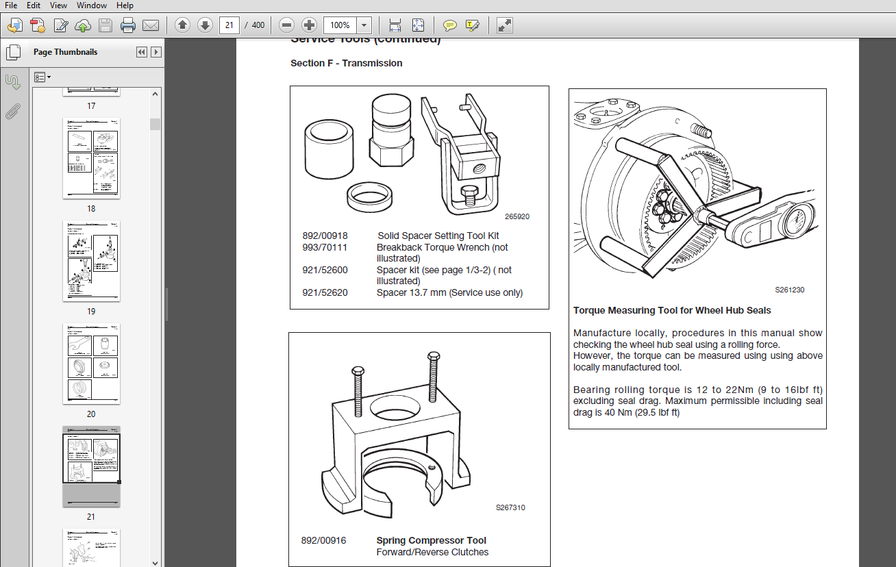
Service Tools
Numerical List
Section B
Section C
Section E
Section F
Section H
Section K
Sealing and Retaining Compounds
Care and Safety
Safety Notices
General Safety
Operating Safety
Maintenance Safety
Lubricants – Health and Safety
Routine Maintenance
Lubricants and Capacities
New Engines
Lubrication Chart (528-70 & 528S Machines)
Machine Safety
Working with Boom Raised
Service Schedules
Grease
Every 50 Hours
Every 500 Hours
Lubricate
Every 500 Hours
Every 1000 Hours
Oiling
Tyres and Wheels
Checking the Footbrake Fluid Level
Engine Air Filter
Cleaning the Pre-Cleaner
Changing the Air Filter Outer Element
Changing the Inner Element
Engine Oil and Filter
Changing the Oil and Filter
Engine Cooling System
Checking the Coolant Level
Coolant Mixtures
Changing the Engine Coolant
Cleaning the Cab Heater Filter
Fuel System
Types of Fuel
Filling the Tank
Cleaning the Lift Pump Gauze
Draining the Fuel Filter
Changing the Filter Element
Draining the Sediment Bowl
Cleaning the Sediment Bowl
Prime the System
Fire Extinguisher
Synchro Shuttle Transmission
Checking the Oil Level
Changing the Oil and Filter
Front and Rear Axle
Checking the Axle Oil Level
Changing the Axle Oil
Front and Rear Hub
Checking/Filling the Hub Oil Levels
Oil Immersed Brakes
Changing the Hub Oil
Hydraulic System
Checking the Fluid Level
Changing the Filter Element
Hose Burst Protection Valves
Boom Lift Ram
Boom Extension Ram
Carriage Tilt Ram
Battery
Warning Symbols
Checking the Electrolyte Level
Body & Framework
Cab
Removal and Replacement
Direct Glazing
Combined Fuel and Hydraulic Tank
Removal and Replacement
Boom
Wear Pads – Removal and Replacement
Inner and Outer – Removal and Replacement
Rivet Nuts – Fitting Procedure
Air Conditioning Option
Technical Data
Safety Procedures
Operation
Control
Wiring Diagram
Fault Finding
Refridgerant Charging and Discharging
Leak Testing
Tightening Leaking Hoses
Air Conditioning Unit Removal and Replacement
Thermostat Removal and Replacement
Pressure Switch Assembly
Electrics
Technical Data
Fuses and Relays
Fuse Identification (528-70 Machines)
Relay Identification (528-70 Machines)
Fuse Identification (528S Machines)
Relay Identification (528S Machines)
Fuse Links
Test Methods
Use of Multimeter
Measuring DC Voltage
Measuring Resistance
Measuring Continuity
How to Test a Diode or a Diode Wire
Wire/Harness Numbers
Schematics
528-70 from 79600 (Synchro Shuttle Transmission)
528S Machines (Powershift Transmission)
528S Machines (Synchro Shuttle Transmission)
Batteries
Safety
Maintenance
Testing – Specific Gravity
Battery Testing
Alternator
Charging Circuit Test
Alternator Charging Test
Terminal ‘W’ OUtput (Tachometer) Test
Removal and Replacement
Dismantling and Assembling
Starter Motor
Starting Circuit Test
Removal and Replacement
Dismantling and Assembling
Safe Load Indicator and Load Moment Indicator
Introduction
Calibration – SLI System
Calibration – LMI System
Fault Finding
Testing
Transducer Removal and Replacement
Parking Brake Switch
Adjustment
Hydraulics
Technical Data
Schematic Circuits
Dual Lever Controls
528S Machines with Single Lever Control
Descriptions
Basic Machine Neutral Circuit
Hydraulic Hitch and Twin Auxilliary Circuit
Fault Finding
Contents
Introduction to Hydraulic Schematic Symbols
Fault Finding Chart
Main Hydraulic Pump
Removal and Replacement
Dismantling, Inspecting and Assembling
Testing
Valves
Valve Block
Removal and Replacement
Dismantling and Assembling
Valve Block Spools
Dismantling and Assembling
Valve Block
528S Machines with Single Lever Control Joystick Dismantling and Assembling
Valve Block Spools
528S Machines with Single Lever Control Joystick Dismantling and Assembling
Main Relief Valve (MRV) Testing
Auxiliary Relief Valve (ARV) Testing
Pilot Pressure Reducing Valve Inspection
Checking Servo Pressure
Diverter Valve – Removal and Replacement
Rams
Lift Ram – Removal and Replacement
Displacement Ram – Removal and Replacement
Extension Ram – Removal and Replacement
Tilt Ram – Removal and Replacement
Typical Ram – Dismantling and Assembly
Transmission
Technical Data
528-70 & 528S
Syncro Shuttle
Powershift
Towing Procedure
Descriptions
Syncro Shuttle and Powershift
Axle View Front and Rear
Syncro Shuttle – Section Views and Torque Figures
Synchromesh – Manual Gearbox
Powershift Transmission
General Description and Operation
Gear Drivepaths
Fault Finding
Syncro Shuttle
Powershift
Torque Converter
Removal and Replacement
Testing
Syncro Shuttle
Powershift
Syncro Shuttle
Section Views and Torque Figures
Dismantling
Assembling
Reverser Unit
Dismantling
Assembling
Powershift
Section Views and Torque Figures
List of Components
Dismantling
Assembly
Input and Reverser Clutch
Dismantling
Assembly
Mainshaft
Dismantling
Assembly
Layshaft
Dismantling
Assembly
Permanent 4 Wheel Drive Unit
Dismantling and Assembly
Solenoid Valve
Collapsible Spacer Assembly
Polytetraflouroethene (PTFE) Piston Ring Seals
Fitting Procedure
Transmission Oil Cooling
Fault Finding
Propshafts
Removal and Replacement
Axles
General Description
Removal and Replacement
Front Axle – SD70
Rear Axle – SD55
Hubs
Dismantling
Assembly
Brakes – Front Axle SD70
Dismantling and Assembly
Drive Head – Front Axle SD70
Dismantling
Assembly
Limited Slip DIfferential Option (SD70)
Drive Head – Rear Axle SD55
Dismantling and Assembly
Crown Wheel and Pinion
Renewing the Pinion OIl Seal
Drive Shaft – Salvage After Oil Seal Failure
Axle and Gearbox Drive Shaft Flange – Salvage After Oil Seal Failure
Drop Box
Removal and Replacement
Dismantling and Assembling
Brakes
Technical Data
Parking Brake
Testing the Parking Brake
Adjustment
Caliper – Removal and Replacement
Checking Brake Pad Wear
Caliper – Dismantling and Assembly
Fault Finding
Break Seal or Component Leakage
Bleeding
Master Cylinder
Removal and Replacement
Steering
Technical Data
Descriptions
General Description
Steer Modes
Steer Unit Operation (AWS)
Steer Unit Operation (3 Steer Modes)
Priority Valve Operation – Neutral
Priority Valve Operation – Turn
Fault Finding
Re-aligning the Road Wheels (AWS)
Realigning the Road Wheels (3 Steer Modes)
Powered Track Rod
Removal and Replacement
Valves
Hydraulic Steering Unit
Dismantling and Assembling
Pressure Relief Valve Cartridge
Shock Valves
Engine
Technical Data
Radiator – Removal & Replacement
Engine and Transmission – Removal and Replacement
Preparing the Machine
Preparing the ENgine for Removal
Preparing the Transmission for Removal
Engine and Transmission Removal and Replacement
Seperating the Engine and Transmission
VIDEO PREVIEW OF THE MANUAL:

IMAGES PREVIEW OF THE MANUAL:


PLEASE NOTE:
- This is the SAME manual used by the dealers to troubleshoot any faults in your vehicle. This can be yours in 2 minutes after the payment is made.
- Contact us at [email protected] should you have any queries before your purchase or that you need any other service / repair / parts operators manual.


King Ty –