

Iveco FI Series S23 S30 Vehicle Application Repair Manual – PDF DOWNLOAD
VIDEO PREVIEW OF THE MANUAL:

IMAGES PREVIEW OF THE MANUAL:
FILE DETAILS:
Iveco FI Series S23 S30 Vehicle Application Repair Manual – PDF DOWNLOAD
Format: PDF
Language: English
Brand: Iveco
DESCRIPTION:
Iveco FI Series S23 S30 Vehicle Application Repair Manual – PDF DOWNLOAD
F1 SERIES
Vehicle application
S23
S23 ENT C
S30
S30 ENT C
Technical and Repair manual
This publication describes the characteristics, data and correct methods for repair operations on each component of the vehicle. If the instructions provided are followed and the specified equipment is used, correct repair operations in the programmed time will be ensured, safeguarding against possible accidents. Before starting to perform whatever type of repair, ensure that all accident prevention equipment is available and efficient.
All protections specified by safety regulations, i.e.: goggles, helmet, gloves, boot, etc. must be checked and worn. All machining, lifting and conveying equipment should be inspected before use. The data contained in this publication was correct at the time of going to press but due to possible modifications made by the Manufacturer for reasons of a technical or commercial nature or for adaptation to the legal requirements of the different countries, some changes may have occurred. No part of this publication, including the pictures, may be reproduced in any form or by any means.
TABLE OF CONTENTS:
Iveco FI Series S23 S30 Vehicle Application Repair Manual – PDF DOWNLOAD
F1 SERIES 1
F1 ENGINES 3
SPECIAL REMARKS 5
PRELIMINARY REMARKS 6
SYMBOLS – WARNINGS 6
Graph and symbols 7
Part 1 – F1A ENGINES 9
UPDATING 11
SECTION 1 – General specifications 13
CORRESPONDENCE BETWEEN TECHNICAL CODE AND COMMERCIAL CODE 15
LUBRICATION 16
General 16
Operation 16
Oil pump 18
Characteristic data 18
Vacuum pump 18
Oil pressure control valve 19
Oil filter 19
Modine heat exchanger 19
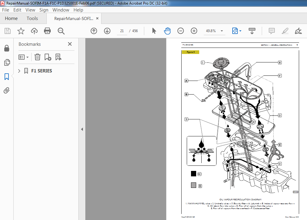
Oil vapour recirculation system 20
Description 20
COOLING 22
Description 22
Operation 22
Electromagnetic pulley (if present) 24
Water pump 24
Thermostat 24
TURBOCHARGING 25
Description 25
Turbocharger 26
EXHAUST GAS RECIRCULATION (EGR) SYSTEM (Illustration, if available) 27
EGR system operation 27
Operating principles 27
Air flow meter 28
SECTION 2 – Fuel 29
OPERATION 31
HYDRAULIC SYSTEM 33
Fuel pump (if provided) 33
Specifications 33
Fuel filter 34
Tightening torques 34
Fuel pipes 34
High-pressure pump 35
High-pressure pump internal structure 37
Working principle 38
Pressure control valve 41
MECHANICAL SUPPLY PUMP 41
Hydraulic accumulator (rail) 42
Overpressure valve (for forged hydraulic accumulator) 42
ELECTRO-INJECTORS 42
Operation 43
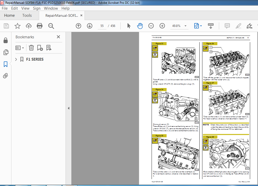
SECTION 3 – Vehicle uses 45
GENERAL SPECIFICATIONS 47
PART ONE – MECHANICAL COMPONENTS 49
OVERHAULING ENGINE F1A 51
DISASSEMBLING THE ENGINE AT THE BENCH 51
MOUNTING 58
Assembling front seal ring 58
Refitting cylinder head 61
Adjusting air-conditioner – compressor drive belt tension 65
Timing speed sensor 69
Engine speed sensor 69
REPAIRS 70
Pressure relief valve 70
Checking and adjusting pressure relief valve 70
Replacing pressure relief valve 70
Replacing pressure regulator 71
PART TWO – ELECTRICAL EQUIPMENT 73
F1A ENGINE HARNESS 75
Injection cable F1A 77
Bosch MS6 3 control unit 79
Control unit connection to the injection cable on engine side (housing A) (EDC MS 6 3) 80
Control unit connection to cab-bonnet cable (housing B) (EDC MS 6 3) 81
Bosch EDC16 control unit 82
EDC 16 control unit connection to the injection cable on engine side (housing A) 83
EDC 16 control unit connection to cab-bonnet cable (housing K) 85
EDC system main components 87
Camshaft sensor 89
RPM sensor 90
Timing sensor 91
Pressure regulator 92
Fuel pressure sensor 93
Air flow meter (without EGR) 95
Atmospheric pressure sensor 97
Engine coolant temperature sensor 97
Fuel temperature sensor 97
Preheat plug electronic centre 98
Preheat plugs 98
Accelerator pedal sensor 99
MAIN COMPONENTS OF POWER NETWORK 100
BOSCH KCBI 14V 110A Alternator 100
EV 12V – 2 3 kW Starter motor 101
SYSTEM OPERATION 102
Self-diagnosis — BLINK CODE 102
Immobilizer recognition (if present) 102
Checking fuel temperature 102
Checking engine coolant temperature 102
Checking quantity of fuel injected 102
Checking idling adjustment 102
Fuel cut-off in release phase 102
Checking cylinder balancing on idling 102
Checking regular engine rotation (anti-sawing) 102
Checking smokiness at exhaust on acceleration 102
Checking exhaust gas recirculation (E G R if present) 102
Checking top speed limit 102
Checking regular rotation on acceleration 102
Checking glow plug control unit 102
Checking activation of air-conditioning system 102
Checking fuel pump 102
Checking diesel warming 103
Checking cylinder position 103
Checking pilot and main injection timing 103
Checking injection pressure closed cycle 103
Fuel supply 103
Correcting flow rate according to water temperature 103
Correcting flow rate to avoid noise, smoke or overloading 103
De-rating 103
Injection timing electronic test 103
Speed governor 103
Engine starting 103
Cold starting 104
Warm starting 104
Run up 104
After run 104
Cut-off 104
Cylinder balancing 104
Synchronization search 104
PART THREE – TROUBLESHOOTING 105
PT-01 PORTABLE TESTER 107
Main functions 107
Test parameters 107
1st Section for engine versions with MS 6 3 ECU 109
BLINK CODE 111
1st Section DTC-FMI error codes with EDC central unit 133
2nd Section SYMPTOMS 173
PART FOUR – MAINTENANCE PLANNING 179
Maintenance 181
MAINTENANCE 183
Recovery 183
Checks not included in maintenance planning-daily checks 183
Inspection and/or maintenance interventions 183
Extra plan operations (to be carried out possibly in combination with maintenance service) 184
SECTION 4 – Features and general overhaul 185
GENERAL SPECIFICATIONS 187
ASSEMBLY DATA — CLEARANCES 188
ENGINE OVERHAUL 193
ENGINE REMOVAL AT THE BENCH 193
REPAIRS 194
CYLINDER BLOCK 194
Checks and measurements 194
Checking head mating surface on cylinder block 195
CRANKSHAFT 195
Measuring main journals and crank pins 195
Checking crankshaft 196
Replacing timing control gear 198
ENGINE ASSEMBLY 198
Assembling main bearings 198
Measuring main journal assembly clearance 198
Checking crankshaft end float 199
Assembling rear seal 200
CONNECTING ROD — PISTON ASSEMBLY 201
Pistons 202
Measuring piston diameter 202
Piston pins 203
Conditions for correct pin-piston coupling 203
Piston rings 203
Connecting rods 204
Bushes 205
Checking connecting rods 205
Checking torsion 205
Checking bending 205
Assembling connecting rod-piston assembly 205
Checking for connecting rod — piston distortion 206
Assembling piston rings 206
Assembling connecting rod — piston assemblies in cylinder barrels 206
Measuring crankpin assembly clearance 207
Checking piston protrusion 207
CYLINDER HEAD 208
Disassembly 208
Removing valves 208
Checking cylinder head seal 208
Checking cylinder head mating surface 209
VALVES 209
Removing deposits, refacing and checking valves 209
Checking clearance between valve stem and valve guide and centring valves 210
VALVE GUIDES 210
Replacing valve guides 210
Boring valve guides 210
VALVE SEATS 211
Regrinding – replacing valve seats 211
VALVE SPRINGS 212
ROCKER ARMS — TAPPETS 212
Checks 213
ASSEMBLING CYLINDER HEADS 213
Overhead 214
Overhead removal 214
TIMING SYSTEM 215
Description 215
Camshaft 216
Checks 216
Checking cam lift and pin alignment 216
Assembling overhead 217
TIGHTENING TORQUE 219
SECTION 5 – Tools 223
TOOLS 225
EXPERIMENTAL TOOLS 230
Appendix 241
SAFETY PRESCRIPTIONS 243
Part 2 – F1C ENGINES 245
UPDATING 247
SECTION 1 – General specifications 249
CORRESPONDENCE BETWEEN TECHNICAL CODE AND COMMERCIAL CODE 251
LUBRICATION 252
General 252
Operation 252
OIL PUMP/DEPRESSOR UNIT 254
Oil pump 254
Characteristic data 254
Vacuum pump 255
Oil pressure adjusting valve 255
Disassembly 255
Assembly 256
Oil filter 256
Heat exchanger 256
Disassembly 256
Assembly 256
Oil vapour recirculation (Blow-by) 258
Operation 258
COOLING 260
Description 260
Operation 260
Electromagnetic pulley (if available) 262
Water pump 262
Thermostat 262
TURBOCHARGING 263
Description 263
Turbocharger type MITSUBISHI TD 4 HL-13T – 6 264
SECTION 2 – Fuel 265
OPERATION 267
HYDRAULIC SYSTEM 267
Fuel pipes 267
Fuel pump 269
Specifications 269
Fuel filter 270
Tightening torques 270
High-pressure pump 271
High-pressure pump internal structure 273
Working principle 274
Pressure control valve 277
MECHANICAL SUPPLY PUMP 277
Hydraulic accumulator (rail) 278
ELECTRO-INJECTORS 278
Operation 278
ELECTRIC/ELECTRONIC COMPONENTS 279
Electronic control unit EDC 16 279
Glow plug electronic control unit 279
Glow plugs 279
Engine speed sensor 279
Camshaft timing sensor 279
SECTION 3 – Vehicle uses 281
GENERAL SPECIFICATIONS 283
PART ONE – MECHANICAL COMPONENTS 285
OVERHAULING ENGINE F1C 287
DISASSEMBLING THE ENGINE AT THE BENCH 287
ASSEMBLY 295
ENGINE FLYWHEEL 296
AUXILIARY PARTS CONTROL ASSEMBLY 296
Cylinder head refitting 298
TIMING SYSTEM CONTROL 299
Oil pump assembly 302
Water pump assembly 303
Replacement of alternator free wheel 304
Steering pump assembly 305
Assembly of high pressure pump and fuel supply 306
Timing speed sensor 309
Engine speed sensor 309
REPAIRS 310
Pressure relief valve 310
Checking and adjusting pressure relief valve 310
Changing the pressure relief valve 310
GARRET GT 2256 T variable geometry turbosupercharger 311
Operation at low engine rpm 311
Operation at high engine rpm 311
Proportional solenoid valve controlling turbocharger actuator 312
Actuator 312
Checking and adjusting the actuator 313
PART TWO – ELECTRICAL EQUIPMENT 315
F1C ENGINE HARNESS 317
Injection cable F1C 317
Bosch EDC16 control unit 319
EDC 16 control unit connection to the injection cable on engine side (housing A) 320
EDC 16 control unit connection to cab-bonnet cable (housing K) 322
EDC system main components 324
Driving shaft and camshaft unit 326
Camshaft revolution sensor 327
Driving shaft revolution sensor 328
Pressure regulator 330
Fuel pressure sensor (Rail) 331
Injectors 332
Airflow gauge 333
Atmospheric pressure sensor 334
Engine coolant temperature sensor 334
Fuel temperature sensor 334
Preheat plug electronic centre 335
Preheat plugs 335
Accelerator pedal sensor 336
Fuel filter 336
MAIN COMPONENTS OF POWER NETWORK 337
BOSCH KCBI 14V 110A Alternator 337
EV 12V – 2 3 kW Starter motor 338
SYSTEM OPERATION 339
Self-diagnosis — BLINK CODE 339
Immobilizer recognition (if present) 339
Checking fuel temperature 339
Checking engine coolant temperature 339
Checking quantity of fuel injected 339
Checking idling adjustment 339
Fuel cut-off in release phase 339
Checking cylinder balancing on idling 339
Checking regular engine rotation (anti-sawing) 339
Checking smokiness at exhaust on acceleration 339
Checking exhaust gas recirculation (E G R if present) 339
Checking top speed limit 339
Checking regular rotation on acceleration 339
Checking glow plug control unit 339
Checking activation of air-conditioning system 339
Checking fuel pump 339
Checking diesel warming 340
Checking cylinder position 340
Checking pilot and main injection timing 340
Checking injection pressure closed cycle 340
Fuel supply 340
Correcting flow rate according to water temperature 340
Correcting flow rate to avoid noise, smoke or overloading 340
De-rating 340
Injection timing electronic test 340
Speed governor 340
Engine starting 340
Cold starting 341
Warm starting 341
Run up 341
After run 341
Cut-off 341
Cylinder balancing 341
Synchronization search 341
PART THREE – TROUBLESHOOTING 343
PT-01 PORTABLE TESTER 345
Main functions 345
Test parameters 345
DTC-FMI error codes with EDC central unit 347
SYMPTOMS 387
PART FOUR – MAINTENANCE PLANNING 393
Maintenance 395
MAINTENANCE 397
Recovery 397
Checks not included in maintenance planning-daily checks 397
Inspection and/or maintenance interventions 397
Extra plan operations (to be carried out possibly in combination with maintenance service) 398
SECTION 4 – Features and general overhaul 399
GENERAL SPECIFICATIONS 401
ASSEMBLY DATA — CLEARANCES 402
ENGINE OVERHAUL 407
REPAIRS 409
CYLINDER BLOCK 409
Checks and measurements 409
Checking head mating surface on cylinder block 410
CRANKSHAFT 410
Measuring main journals and crank pins 410
Checking crankshaft 411
Replacing timing control gear 413
ENGINE ASSEMBLY 413
Assembling main bearings 413
Measuring main journal assembly clearance 413
Checking crankshaft end float 414
Assembling rear seal 415
CONNECTING ROD — PISTON ASSEMBLY 416
Pistons 417
Measuring piston diameter 417
Piston pins 417
Conditions for correct pin-piston coupling 417
Piston rings 418
Connecting rods 419
Bushing 419
Checking connecting rods 419
Checking torsion 420
Checking bending 420
Assembling connecting rod-piston assembly 420
Checking for connecting rod — piston distortion 421
Assembling piston rings 421
Assembling connecting rod — piston assemblies in cylinder barrels 421
Measuring crankpin assembly clearance 421
Checking piston protrusion 422
CYLINDER HEAD 423
Disassembly 423
Disassembling valves 423
Checking cylinder head seal 424
Checking cylinder head mating surface 424
VALVES 424
Removing deposits, refacing and checking valves 424
Checking clearance between valve stem and valve guide and centring valves 425
VALVE GUIDES 425
Replacing valve guide 425
Boring valve guides 425
VALVE SEATS 426
Regrinding – replacing valve seats 426
VALVE SPRINGS 427
ROCKER ARMS — TAPPETS 427
Checks 428
ASSEMBLING CYLINDER HEADS 428
Overhead 429
Overhead removal 429
TIMING SYSTEM 430
Description 430
Camshaft 431
Checks 431
Checking cam lift and pin alignment 431
Assembling overhead 432
TIGHTENING TORQUE 433
SECTION 5 – Tools 437
TOOLS 439
EXPERIMENTAL TOOLS 445
Appendix 453
SAFETY PRESCRIPTIONS 455
PLEASE NOTE:
- This is the same manual used by the dealers to diagnose and troubleshoot your vehicle
- You will be directed to the download page as soon as the purchase is completed. The whole payment and downloading process will take anywhere between 2-5 minutes
- Need any other service / repair / parts manual, please feel free to contact [email protected] . We still have 50,000 manuals unlisted


