

Hyster B60ZAC (C230) Parts Manual – PDF DOWNLOAD
DESCRIPTION:
Hyster B60ZAC (C230) Parts Manual – PDF DOWNLOAD
HOW TO USE THE ILLUSTRATED PARTS MANUAL :
- This parts manual describes and illustrates assemblies, sub-assemblies, and detail parts needed for service replacement.
- The different constructions are indicated by keys and footnotes. The call outs correspond to descriptions found on the next page.
HOW TO FIND THE DESIRED PART NUMBER
WHEN THE PART NUMBER AND THE NEXT HIGHER ASSEMBLY IS NOT KNOWN:
1. Determine the function and application of the part required. Turn to the Sections Page. Choose the general area of reference most likely to include the part.
WHEN THE PART NUMBER AND THE NEXT HIGHER ASSEMBLY IS NOT KNOWN:
1. Determine the function and application of the part required. Turn to the Sections Page. Choose the general area of reference most likely to include the part.
2. Turn to the section you chose. Use the Section Table of Contents to determine the assembly which would normally contain the part required. Then locate the part on the assembly breakdown page.
WHEN THE PART NUMBER IS NOT KNOWN AND THE NEXT HIGHER ASSEMBLY IS KNOWN:
3. Determine the assembly the required part is used on. Turn to the Table of Contents (Page i).
WHEN THE PART NUMBER IS NOT KNOWN AND THE NEXT HIGHER ASSEMBLY IS KNOWN:
3. Determine the assembly the required part is used on. Turn to the Table of Contents (Page i).
4. Locate the assembly the required part is used on and turn to the page indicated for that assembly. Then locate the part on the assembly breakdown page.
WHEN THE PART NUMBER IS KNOWN:
5. Use the Numerical Index (Page 7-1) to find the part number. Turn to the page listed and locate the part as indicated by the item number.
GENERAL:
The assembly breakdowns include part numbers, descriptions, quantities required, keys and footnotes to help in selecting correct parts.
6. Parts Super session Information. Part numbers that have this history will be displayed in the parts list in the order that they were superseded (from oldest to newest). The superseded part numbers will be shown with a line through them.
- Five periods in the PART NO. column (. . . . .) indicate that the part is either Not Serviced Separately or there is a reference to another figure. A figure reference is denoted by a pointing hand followed by a figure number in the DESCRIPTION column (Figure 10)
7. Keys are used to show two or more similar assemblies, RH and LH assembly parts, etc. Select the appropriate key, “A”, “B”, “C”, “D”, or “E” and the corresponding quantity column to find the required parts. Two periods in the QTY column (..) indicate that the part is not used for that assembly.
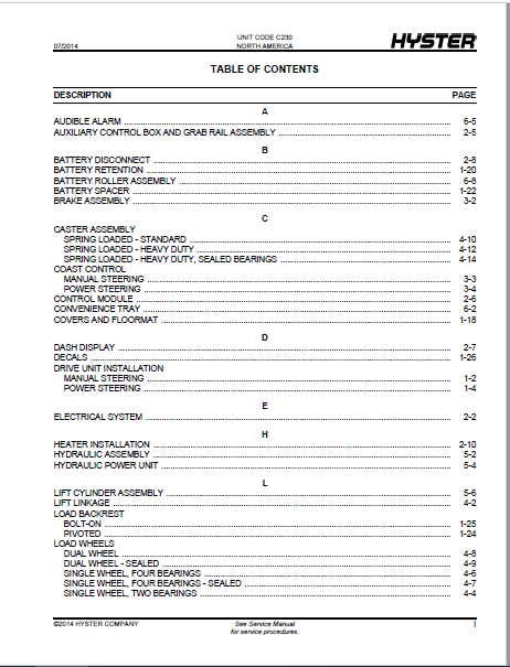
TABLE OF CONTENTS:
Hyster B60ZAC (C230) Parts Manual – PDF DOWNLOAD
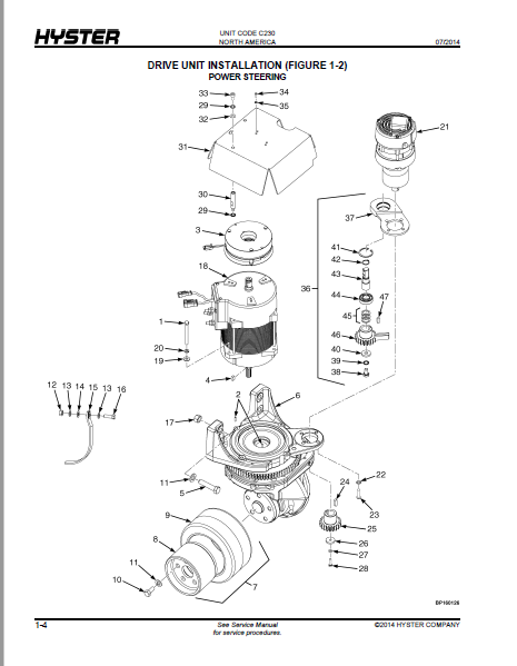
FRAME/DRIVE UNIT.................................................................................... 13
	DRIVE UNIT INSTALLATION MANUAL STEERING......................................................... 16
	DRIVE UNIT INSTALLATION POWER STEERING.......................................................... 18
	MASTER DRIVE UNIT MANUAL STEERING............................................................... 22
	MASTER DRIVE UNIT POWER STEERING................................................................ 26
	TRACTION MOTOR ASSEMBLY......................................................................... 30
	COVERS AND FLOORMAT............................................................................. 32
	BATTERY RETENTION............................................................................... 34
	BATTERY SPACER.................................................................................. 36
	LOAD BACKREST PIVOTED........................................................................... 38
	LOAD BACKREST BOLT-ON........................................................................... 39
	DECALS.......................................................................................... 40
ELECTRICAL SYSTEM................................................................................... 43
	ELECTRICAL SYSTEM............................................................................... 46
	AUXILIARY CONTROL BOX AND GRAB RAIL ASSEMBLY.................................................... 49
	CONTROL MODULE.................................................................................. 50
	DASH DISPLAY.................................................................................... 51
	BATTERY DISCONNECT.............................................................................. 52
	HEATER INSTALLATION............................................................................. 54
	WIRE HARNESS TILLER HANDLE - COMPOSITE HANDLE, MANUAL STEERING ................................. 56
	WIRE HARNESS TILLER HANDLE - METAL HANDLE, POWER STEERING ...................................... 58
	WIRE HARNESS MANUAL STEERING.................................................................... 60
	WIRE HARNESS MANUAL STEERING - ALTERNATE PART, PAGE 1 OF 2 ..................................... 64
	WIRE HARNESS MANUAL STEERING - ALTERNATE PART, PAGE 2 OF 2 ..................................... 66
	WIRE HARNESS POWER STEERING..................................................................... 68
	WIRE HARNESS POWER STEERING - ALTERNATE PART, PAGE 1 OF 2 ...................................... 72
	WIRE HARNESS POWER STEERING - ALTERNATE PART, PAGE 2 OF 2 ...................................... 76
	WIRE HARNESS HANDRAIL........................................................................... 79
	WIRE HARNESS SIDE GLIDE......................................................................... 80
	WIRE HARNESS ADVANCED COAST CONTROL - MANUAL STEERING .......................................... 81
	WIRE HARNESS ADVANCED COAST CONTROL - POWER STEERING ........................................... 82
	WIRE HARNESS MICRO SWITCH - TILLER SWITCH INSTALLATION ......................................... 83
	WIRE HARNESS MICRO SWITCH - HEATER INSTALLATION ................................................ 84
	WIRE HARNESS STROBE LIGHT....................................................................... 85
	WIRE HARNESS RF TERMINAL........................................................................ 86
	WIRE HARNESS HEATER............................................................................. 88
	WIRE HARNESS THERMOSTAT......................................................................... 89
	WIRE HARNESS AUDIBLE ALARM...................................................................... 90
	WIRE HARNESS COAST CONTROL - MANUAL STEERING ................................................... 91
STEER HANDLE/BRAKE SYSTEM........................................................................... 93
	BRAKE ASSEMBLY.................................................................................. 96
	COAST CONTROL MANUAL STEERING................................................................... 97
	COAST CONTROL POWER STEERING.................................................................... 98
	TILLER ARM ASSEMBLY COMPOSITE HANDLE - MANUAL STEERING .........................................100
	TILLER ARM ASSEMBLY METAL HANDLE - POWER STEERING ..............................................102
	TILLER HEAD ASSEMBLY COMPOSITE - MANUAL STEERING ...............................................104
	TILLER HEAD ASSEMBLY METAL HANDLE - POWER STEERING .............................................108
	TILLER SWIVEL ASSEMBLY WITHOUT COAST CONTROL OR WITH MANUAL COAST CONTROL - POWER STEERING .....112
	TILLER SWIVEL ASSEMBLY WITH COAST CONTROL - POWER STEERING .....................................116
	TILLER SWIVEL ASSEMBLY WITHOUT COAST CONTROL OR WITH MANUAL COAST CONTROL - MANUAL STEERING ....120
	TILLER SWIVEL ASSEMBLY WITH COAST CONTROL - MANUAL STEERING ....................................122
LIFT LINKAGE, LOAD WHEELS, AND FORKS................................................................125
	LIFT LINKAGE....................................................................................128
	LOAD WHEELS SINGLE WHEEL, TWO BEARINGS..........................................................130
	LOAD WHEELS SINGLE WHEEL, TWO BEARINGS - SEALED ................................................131
	LOAD WHEELS SINGLE WHEEL, FOUR BEARINGS.........................................................132
	LOAD WHEELS SINGLE WHEEL, FOUR BEARINGS - SEALED ...............................................133
	LOAD WHEELS DUAL WHEEL..........................................................................134
	LOAD WHEELS DUAL WHEEL - SEALED ................................................................135
	CASTER ASSEMBLY SPRING LOADED - STANDARD .......................................................136
	CASTER ASSEMBLY SPRING LOADED - HEAVY DUTY .....................................................138
	CASTER ASSEMBLY SPRING LOADED - HEAVY DUTY, SEALED BEARINGS ....................................140
HYDRAULIC SYSTEM....................................................................................143
	HYDRAULIC ASSEMBLY..............................................................................146
	HYDRAULIC POWER UNIT............................................................................148
	LIFT CYLINDER ASSEMBLY..........................................................................150
OPTIONS.............................................................................................151
	CONVENIENCE TRAY................................................................................154
	RF TERMINAL.....................................................................................156
	AUDIBLE ALARM...................................................................................157
	VISIBLE ALARM...................................................................................158
	BATTERY ROLLER ASSEMBLY.........................................................................160
	STEER STOP ADVANCED COAST CONTROL...............................................................162
NUMERICAL INDEX.....................................................................................163
IMAGES PREVIEW OF THE MANUAL:

VIDEO PREVIEW OF THE MANUAL:

PLEASE NOTE:
- This is the SAME manual used by the dealers to troubleshoot any faults in your vehicle. This can be yours in 2 minutes after the payment is made.
- Contact us at [email protected] should you have any queries before your purchase or that you need any other service / repair / parts operators manual.
S.V


