

Hitachi ZX240-5A , ZX240LC-5A , ZX250H-5A , ZX250LCH-5A , ZX250K-5A , ZX250LCK-5A Hydraulic Excavator Service Repair Manual
File Details:
Hitachi ZX240-5A , ZX240LC-5A , ZX250H-5A , ZX250LCH-5A , ZX250K-5A , ZX250LCK-5A Hydraulic Excavator Service Repair Manual
- Manual Language:English
- Pages: 1500+
- Size: 5.57 MB
- Downloadable:Yes
- Format:PDF
Video Preview:

Image Preview:

Description:
Hitachi ZX240-5A , ZX240LC-5A , ZX250H-5A , ZX250LCH-5A , ZX250K-5A , ZX250LCK-5A Hydraulic Excavator Service Repair Manual
TO THE READER
This manual is written for an experienced technician to provide technical information needed to maintain and repair this machine. The machine specification and description according to destination may be explained on this manual.
• Be sure to thoroughly read this manual for correct product information and service procedures.
• If you have any questions or comments, at if you found any errors regarding the contents of this manual, please contact using “Service Manual Revision Request Form” at the end of this manual.
ADDITIONAL REFERENCES
Please refer to the other materials (operator’s manual, parts catalog, engine technical material and Hitachi training material etc.) in addition to this manual.
MANUAL COMPOSITION
This manual consists the Technical Manual and the Workshop Manual.
• Information included in the Technical Manual: technical information needed for redelivery and delivery, operation and activation of all devices and systems, operational performance tests, and troubleshooting procedures.
• Information included in the Workshop Manual: technical information needed for maintenance and repair of the machine, tools and devices needed for maintenance and repair, maintenance standards, and removal/installation and assemble/ disassemble procedures.
Table Of Contents:
Hitachi ZX240-5A , ZX240LC-5A , ZX250H-5A , ZX250LCH-5A , ZX250K-5A , ZX250LCK-5A Hydraulic Excavator Service Repair Manual
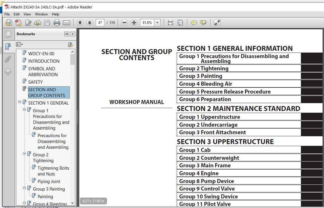
WDCY-EN-00...........................................................  1
INTRODUCTION.........................................................  3
SYMBOL AND ABBREVIATION..............................................  5
SAFETY...............................................................  7
SECTION AND GROUP CONTENTS........................................... 47
SECTION 1 GENERAL.................................................... 49
	Group 1 Precautions for Disassembling and Assembling............. 51
		Precautions for Disassembling and Assembling................. 51
	Group 2 Tightening............................................... 57
		Tightening Bolts and Nuts.................................... 57
		Piping Joint................................................. 60
	Group 3 Painting................................................. 65
		Painting..................................................... 65
	Group 4 Bleeding Air............................................. 67
		Bleeding Air from Hydraulic Oil Tank......................... 67
		Bleeding Air from Hydraulic System........................... 68
		Bleeding Air from Fuel System................................ 69
		Bleeding Air from Radiator................................... 71
	Group 5 Pressure Release Procedure............................... 73
		Hydraulic Circuit Pressure Release Procedure................. 73
	Group 6 Preparation.............................................. 75
		Preparation before Inspection and Maintenance................ 75
SECTION 2 MAINTENANCE STANDARD....................................... 79
	Group 1 Upperstructure........................................... 81
		Pump Device.................................................. 81
		Swing Motor.................................................. 85
	Group 2 Undercarriage............................................ 89
		Travel Motor................................................. 89
		Sprocket..................................................... 91
		Front Idler.................................................. 93
		Upper Roller................................................. 95
		Lower Roller................................................. 96
		Track........................................................ 97
	Group 3 Front Attachment.........................................101
		Pin and Bushing..............................................101
		Side Cutter (2021232, 2021233)...............................103
		Point (4512365)..............................................104
		Standard Dimensions for Arm and Bucket Connection............105
		Standard Dimensions for Arm and Boom Connection..............106
		Cylinder.....................................................107
SECTION 3 UPPERSTRUCTURE.............................................111
	Group 1 Cab......................................................113
		Removal and Installation of Cab..............................113
		Dimensions of Cab Glass......................................139
	Group 2 Counterweight............................................159
		Removal and Installation of Counterweight....................159
	Group 3 Main Frame...............................................161
		Removal and Installation of Main Frame.......................161
	Group 4 Engine...................................................169
		Removal and Installation of Engine...........................169
	Group 8 Pump Device..............................................199
		Removal and Installation of Pump Device......................199
		Removal and Installation of Coupling.........................215
		Disassembly of Pump Device...................................217
		Assembly of Pump Device......................................224
		Disassembly of Regulator.....................................235
		Assembly of Regulator........................................237
		Disassembly of Solenoid Valve................................239
		Assembly of Solenoid Valve...................................241
		Structure of Pilot Pump......................................243
	Group 9 Control Valve............................................245
		Removal Installation of Control Valve........................245
		Disassembly of Housing.......................................267
		Assembly of Housing..........................................269
		Disassembly of Control Valve (4-Spool Side)..................271
		Assembly of Control Valve (4-Spool Side).....................278
		Disassembly of Control Valve (5-Spool Side)..................289
		Assembly of Control Valve (5-Spool Side).....................296
	Group 10 Swing Device............................................305
		Removal and Installation of Swing Device.....................305
		Disassembly of Swing Device..................................309
		Assembly of Swing Device.....................................314
		Disassembly of Swing Motor...................................321
		Assembly of Swing Motor......................................324
	Group 11 Pilot Valve.............................................327
		Removal and Installation of Pilot Valve (Left)...............327
		Removal and Installation of Pilot Valve (Right)..............333
		Removal and Installation of Travel Pilot Valve...............341
		Disassembly of Pilot Valves (Right and Left).................345
		Assembly of Pilot Valves (Right and Left)....................348
		Disassembly of Travel Pilot Valve............................351
		Assembly of Travel Pilot Valve...............................355
	Group 12 Solenoid Valve..........................................361
		Removal and Installation of Pilot Shut-Off Solenoid Valve....361
		Removal and Installation of 3-Spool Solenoid Valve Unit......365
		Disassembly of Pilot Shut-Off Solenoid Valve.................371
		Assembly of Pilot Shut-Off Solenoid Valve....................373
		Structure of 3-Spool Solenoid Valve Unit.....................375
	Group 13 Signal Control Valve....................................377
		Removal and Installation of Signal Control Valve.............377
		Structure of Signal Control Valve............................381
SECTION 4 UNDERCARRIAGE..............................................385
	Group 1 Swing Bearing............................................387
		Removal and Installation of Swing Bearing....................387
		Disassembly of Swing Bearing.................................391
		Assembly of Swing Bearing....................................394
	Group 2 Travel Device............................................397
		Removal and Installation of Travel Device....................397
		Disassembly of Travel Device.................................401
		Assembly of Travel Device....................................405
		Disassembly of Travel Motor..................................413
		Assembly of Travel Motor.....................................416
		Disassembly of Brake Valve...................................421
		Assembly of Brake Valve......................................423
		Precautions for Using Floating Seal..........................425
	Group 3 Center Joint.............................................427
		Removal and Installation of Center Joint.....................427
		Disassembly of Center Joint..................................431
		Assembly of Center Joint.....................................433
		Replacement of Body and Spindle..............................436
	Group 4 Track Adjuster...........................................437
		Removal and Installation of Track Adjuster...................437
		Disassembly of Front Idler...................................441
		Assembly of Front Idler......................................444
		Disassembly of Track Adjuster................................447
		Assembly of Track Adjuster...................................451
		Precautions for Using Floating Seal..........................455
	Group 5 Upper and Lower Rollers..................................457
		Removal and Installation of Upper Roller.....................457
		Removal and Installation of Lower Roller.....................461
		Disassembly of Lower Roller..................................467
		Assembly of Lower Roller.....................................469
		Precautions for Using Floating Seal..........................471
	Group 6 Track....................................................473
		Removal and Installation of Track............................473
SECTION 5 FRONT ATTACHMENT...........................................481
	Group 1 Front Attachment.........................................483
		Removal and Installation of Front Attachment.................483
	Group 2 Cylinder.................................................491
		Removal and Installation of Boom Cylinder....................491
		Removal and Installation of Arm Cylinder.....................495
		Removal and Installation of Bucket Cylinder..................501
		Disassembly of Boom, Arm, and Bucket Cylinders...............505
		Assembly of Boom, Arm, and Bucket Cylinders..................509
SERVICE MANUAL REVISION REQUEST FORM.................................515
Please Note:
⦁ This is the SAME exact manual used by your dealers to fix your vehicle.
⦁ The same can be yours in the next 2-3 mins as you will be directed to the download page immediately after paying for the manual.
⦁ Any queries / doubts regarding your purchase, please feel free to contact [email protected]


Keanu Rodrigo –
All is ok.