

Hitachi Zx 450 3 450 470 500 Zaxis Technical Manual
FILE DETAILS:
Hitachi Zx 450 3 450 470 500 Zaxis Technical Manual
LANGUAGE:ENGLISH
PAGES:586
DOWNLOADABLE:YES
FILE TYPE:PDF
VIDEO PREVIEW OF THE MANUAL:

IMAGES PREVIEW OF THE MANUAL:


DESCRIPTION:
- Hitachi Zx 450 3 450 470 500 Zaxis Technical Manual
- This manual consists of three portions: the Technical Manual (Operational Principle), the Technical Manual (Troubleshooting) and the Workshop Manual. Information included in the Technical Manual (Operational Principle): technical information needed for redelivery and delivery, operation and activation of all devices and systems.
- Information included in the Technical Manual (Troubleshooting): technical information needed for operational performance tests, and troubleshooting procedures. Information included in the Workshop Manual: technical information needed for maintenance and repair of the machine, tools and devices needed for maintenance and repair, maintenance standards, and removal/installation and assemble/ disassemble procedures.
TABLE OF CONTENTS:
Hitachi Zx 450 3 450 470 500 Zaxis Technical Manual
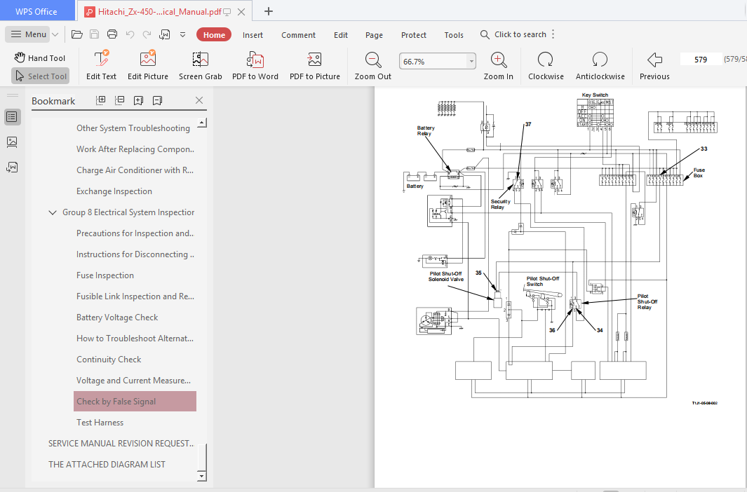
COVER.......................................................................................  1
INTRODUCTION................................................................................  3
SAFETY......................................................................................  5
SECTION AND GROUP CONTENTS.................................................................. 41
SECTION 4 OPERATIONAL PERFORMANCE TEST...................................................... 43
	Group 1 Introduction.................................................................... 45
		Operational Performance Tests....................................................... 45
		Preparation for Performance Tests................................................... 46
	Group 2 Standard........................................................................ 47
		Operational Performance Standard Table.............................................. 47
		Main Pump P-Q Diagram............................................................... 51
		Fan Pump P-Q Diagram................................................................ 52
		Fan Pump I-Q Diagram................................................................ 53
		Dr.ZX Monitor Indicating Values (MC)................................................ 54
		Dr.ZX Monitor Indicating Values (ECM)............................................... 60
		Sensor Activating Range............................................................. 61
	Group 3 Engine Test..................................................................... 63
		Engine Speed........................................................................ 63
		Engine Compression Pressure......................................................... 65
		Valve Clearance..................................................................... 66
		Lubricant Consumption............................................................... 69
	Group 4 Excavator Test.................................................................. 71
		Travel Speed........................................................................ 71
		Track Revolution Speed.............................................................. 72
		Mistrack Check...................................................................... 73
		Travel Motor Leakage................................................................ 74
		Swing Speed......................................................................... 75
		Swing Function Drift Check.......................................................... 76
		Swing Motor Leakage................................................................. 77
		Maximum Swingable Slant Angle....................................................... 78
		Swing Bearing Play.................................................................. 80
		Hydraulic Cylinder Cycle Time....................................................... 82
		Dig Function Drift Check............................................................ 84
		Control Lever Operating Force....................................................... 85
		Control Lever Stroke................................................................ 86
		Boom Raise/Swing Combined Operation Check........................................... 87
	Group 5 Component Test.................................................................. 89
		Primary Pilot Pressure.............................................................. 89
		Secondary Pilot Pressure............................................................ 91
		Solenoid Valve Set Pressure......................................................... 92
		Main Pump Delivery Pressure......................................................... 94
		Fan Pump Delivery Pressure.......................................................... 95
		Main Relief Valve Set Pressure...................................................... 96
		Overload Relief Valve Set Pressure..................................................100
		Main Pump Flow Rate Measurement.....................................................102
		Fan Pump Flow Rate Measurement......................................................104
		Swing Motor Drainage................................................................110
		Travel Motor Drainage...............................................................112
	Group 6 Adjustment......................................................................115
		Pump Learning.......................................................................115
		Torque Adjustment...................................................................121
SECTION 5 TROUBLESHOOTING...................................................................127
	Group 1 Diagnosing Procedure............................................................131
		Introduction........................................................................131
		Diagnosing Procedure................................................................132
	Group 2 Monitor Unit....................................................................137
		Outline.............................................................................137
		How to Use Screens..................................................................146
		Screen Display When An Alarm is Issued..............................................154
		Contents of Alarms..................................................................156
		Troubleshooting.....................................................................158
		Controller Version..................................................................160
		Monitoring..........................................................................162
		Displaying Operating Conditions.....................................................165
		Pump 2 Flow Rate Adjustment.........................................................166
		Attachment Selection................................................................168
		Time Set............................................................................171
		Fuel Rate Display/No Display........................................................172
		Back Monitor Settings...............................................................176
		Maintenance Settings................................................................183
		Language Settings...................................................................188
		Mail (Optional).....................................................................190
	Group 3 Dr. ZX..........................................................................193
		Outline.............................................................................193
		Self-Diagnostic Results.............................................................196
		Select Controller...................................................................198
		Main Controller.....................................................................199
		Main Menu Monitor Display (MC)......................................................200
		Special Functions...................................................................206
		Setup...............................................................................208
		Adjustment Data List................................................................212
		Attachment Adjustment Data List.....................................................213
		Engine Controller...................................................................234
		Main Menu Monitor Display (ECM).....................................................235
		Record Data Display.................................................................238
		Password Change.....................................................................239
		ICF Controller......................................................................240
		Main Menu Information C/U Various Setup.............................................241
		Information C/U: Initialize.........................................................242
		Enter Model and Serial No...........................................................243
		Enter Date and Time.................................................................244
		Control Data: Initialize............................................................245
		Satellite Terminal: Initialize......................................................246
		Satellite Terminal No. Confirmation.................................................247
		Communicating State Check...........................................................248
		Enter Satellite Comm. Start / Stop Set .............................................249
		Data Download.......................................................................251
		Save Data Check.....................................................................252
		Password Change.....................................................................253
		Monitor Controller..................................................................254
		Monitoring..........................................................................255
		Various Settings....................................................................258
		Option Function Allocate............................................................260
		Overload Warning Enable / Disable Selection.........................................268
		Back Monitor Setup..................................................................270
		Operational Condition Enable / Disable Selection....................................274
		Time Set Function Enable / Disable Selection........................................276
		Maintenance Setup Maintenance Operation Allow / Not Allow Selection.................278
		Notification Function Enable / Disable Selection....................................280
		Maintenance Display Items On/Off Selection..........................................282
		Internal Hour Meter Synchronization.................................................286
		Fuel Cost Meter Display Enable / Disable Selection..................................287
		Password Change.....................................................................289
	Group 4 ICF.............................................................................291
		Outline.............................................................................291
		List of Daily Report Data...........................................................292
		List of Frequency Distribution Data.................................................295
		List of Total Operating Hours.......................................................296
		How to Download and Upload Data of ICF..............................................298
		Various Setup of ICF and Satellite Communication Terminal by Using Dr. ZX...........301
		List of Fault Code..................................................................313
		Satellite Communication System......................................................314
	Group 5 Component Layout................................................................317
		Main Component Layout...............................................................317
		Electrical Component Layout.........................................................319
		Engine..............................................................................325
		Pump Device.........................................................................326
		Swing Device........................................................................326
		Travel Device.......................................................................326
		Control Valve.......................................................................327
		Components in Control Valve.........................................................328
		Pilot Port..........................................................................338
	Group 6 Troubleshooting A...............................................................343
		Troubleshooting A Procedure.........................................................343
		MC Fault Code List..................................................................344
		ECM Fault Code List.................................................................364
		ICF Fault Code List.................................................................376
		Satellite Terminal Fault Code List (Optional).......................................377
		Monitor Unit Fault Code List........................................................378
		MC Fault Code 11000 to 11002........................................................379
		MC Fault Code 11003.................................................................380
		MC Fault Code 11004.................................................................381
		CAN Harness Check...................................................................382
		MC Fault Code 11101.................................................................402
		MC Fault Code 11200.................................................................403
		MC Fault Code 11202.................................................................404
		MC Fault Code 11301.................................................................405
		MC Fault Code 11302.................................................................406
		MC Fault Code 11303.................................................................407
		MC Fault Code 11400.................................................................408
		MC Fault Code 11402.................................................................409
		MC Fault Code 11404.................................................................410
		MC Fault Code 11405.................................................................411
		MC Fault Code 11410.................................................................412
		MC Fault Code 11412.................................................................413
		MC Fault Code 11802.................................................................414
		MC Fault Code 11901.................................................................415
		MC Fault Codes 11910, 11911, 11914, 11918, 11920, 11983, 11984......................417
		MC Fault Codes 11910, 11911, 11914, 11918, 11920, 11983, 11984 CAN Harness Check....418
		MC Fault Code 11989.................................................................421
		MC Fault Code 11991.................................................................422
		MC Fault Code 11992.................................................................423
		MC Fault Code 11993.................................................................424
		MC Fault Code 11994.................................................................425
		MC Fault Code 11995.................................................................426
		MC Fault Code 11997.................................................................427
		MC Fault Code 11998.................................................................428
		MC Fault Code 11999.................................................................429
		ICF Fault Codes 14000 to 14003......................................................431
		Information C/U: Initialize.........................................................432
		Control Data: Initialize............................................................433
		Enter Model and Serial No...........................................................434
		ICF Fault Codes 14006, 14008........................................................435
		Satellite Terminal (Optional) Fault Codes 14100 to 14106............................436
		Monitor Unit Fault Code 13303.......................................................437
		Monitor Unit Fault Code 13304.......................................................438
		Monitor Unit Fault Codes 13306, 13308...............................................439
		Monitor Unit Fault Code 13310.......................................................440
		Monitor Unit Fault Code 13311.......................................................441
		Pilot Shut-Off Lever Alarm..........................................................442
	Group 7 Troubleshooting B...............................................................443
		Troubleshooting B Procedure.........................................................443
		Relationship between Machine Trouble Symptoms and Related Parts.....................444
		Correlation between Trouble Symptoms and Part Failures..............................462
		Engine System Troubleshooting.......................................................478
		All Actuator System Troubleshooting.................................................496
		Front Attachment System Troubleshooting.............................................506
		Swing System Troubleshooting........................................................516
		Travel System Troubleshooting.......................................................519
		Other System Troubleshooting........................................................524
		Work After Replacing Components.....................................................550
		Charge Air Conditioner with Refrigerant.............................................551
		Exchange Inspection.................................................................560
	Group 8 Electrical System Inspection....................................................565
		Precautions for Inspection and Maintenance..........................................565
		Instructions for Disconnecting Connectors...........................................567
		Fuse Inspection.....................................................................568
		Fusible Link Inspection and Replacement.............................................570
		Battery Voltage Check...............................................................570
		How to Troubleshoot Alternator Malfunctions.........................................571
		Continuity Check....................................................................572
		Voltage and Current Measurement.....................................................574
		Check by False Signal...............................................................581
		Test Harness........................................................................582
SERVICE MANUAL REVISION REQUEST FORM........................................................585
THE ATTACHED DIAGRAM LIST...................................................................586
PLEASE NOTE:
⦁ This is the same manual used by the dealers to diagnose and troubleshoot your vehicle
⦁ You will be directed to the download page as soon as the purchase is completed. The whole payment and downloading process will take anywhere between 2-5 minutes
⦁ Need any other service / repair / parts manual, please feel free to contact [email protected] . We still have 50,000 manuals unlisted


Amari Graysen –
It has been great. I have ordered multiple manuals for equipment we use on our fa4m
Kristopher –
I had trouble opening the Manual so I contacted the company & they emailed me a .pdf of the manual which opened quickly & was easy to read.