

")
")
Hitachi ZX 225USLC-5B 225USRLC-5B Hydraulic Excavator Workshop Manual
File Details:
Hitachi ZX 225USLC-5B 225USRLC-5B Hydraulic Excavator Workshop Manual
- Manual Language:English
- Pages: 1100+
- Size: 13.5 MB
- Downloadable:Yes
- Format:PDF
Video Preview:

Image Preview:

Description:
Hitachi ZX 225USLC-5B 225USRLC-5B Hydraulic Excavator Workshop Manual
TO THE READER
This manual is written for an experienced technician to provide technical information needed to maintain and repair this machine. The machine specification and description according to destination may be explained on this manual.
• Be sure to thoroughly read this manual for correct product information and service procedures.
• If you have any questions or comments, at if you found any errors regarding the contents of this manual, please contact using “Service Manual Revision Request Form” at the end of this manual.
ADDITIONAL REFERENCES
Please refer to the other materials (operator’s manual, parts catalog, engine technical material and Hitachi training material etc.) in addition to this manual.
MANUAL COMPOSITION
This manual consists the Technical Manual and the Workshop Manual.
• Information included in the Technical Manual: technical information needed for redelivery and delivery, operation and activation of all devices and systems, operational performance tests, and troubleshooting procedures.
• Information included in the Workshop Manual: technical information needed for maintenance and repair of the machine, tools and devices needed for maintenance and repair, maintenance standards, and removal/installation and assemble/ disassemble procedures.
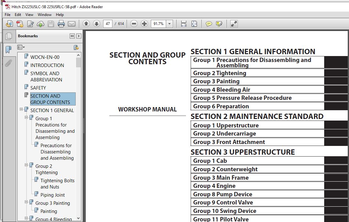
Table Of Contents:
Hitachi ZX 225USLC-5B 225USRLC-5B Hydraulic Excavator Workshop Manual
WDCN-EN-00..................................................................  1
INTRODUCTION................................................................  3
SYMBOL AND ABBREVIATION.....................................................  5
SAFETY......................................................................  7
SECTION AND GROUP CONTENTS.................................................. 47
SECTION 1 GENERAL........................................................... 49
	Group 1 Precautions for Disassembling and Assembling.................... 51
		Precautions for Disassembling and Assembling........................ 51
	Group 2 Tightening...................................................... 57
		Tightening Bolts and Nuts........................................... 57
		Piping Joint........................................................ 60
	Group 3 Painting........................................................ 67
		Painting............................................................ 67
	Group 4 Bleeding Air.................................................... 69
		Bleeding Air from Hydraulic Oil Tank................................ 69
		Bleeding Air from Hydraulic System.................................. 70
		Bleeding Air from Fuel System....................................... 71
		Bleeding Air from Radiator.......................................... 73
	Group 5 Pressure Release Procedure...................................... 75
		Hydraulic Circuit Pressure Release Procedure........................ 75
	Group 6 Preparation..................................................... 77
		Preparation before Inspection and Maintenance....................... 77
SECTION 2 MAINTENANCE STANDARD.............................................. 81
	Group 1 Upperstructure.................................................. 83
		Pump Device......................................................... 83
		Swing Motor......................................................... 87
	Group 2 Undercarriage................................................... 91
		Travel Motor........................................................ 91
		Sprocket............................................................ 93
		Front Idler......................................................... 95
		Upper Roller........................................................ 97
		Lower Roller........................................................ 98
		Track............................................................... 99
	Group 3 Front Attachment................................................103
		Pin and Bushing.....................................................103
		Side Cutter (2014503, 2014504)......................................105
		Point (4427919).....................................................106
		Standard Dimensions for Arm and Bucket Connection...................107
		Standard Dimensions for Arm and Boom Connection.....................108
		Cylinder............................................................109
SECTION 3 UPPERSTRUCTURE....................................................113
	Group 1 Cab.............................................................115
		Removal and Installation of Cab.....................................115
		Dimensions of Cab Glass.............................................143
	Group 2 Counterweight...................................................163
		Removal and Installation of Counterweight (ZX225USLC-5B)............163
		Removal and Installation of Counterweight (ZX225USRLC-5B)...........165
	Group 3 Main Frame......................................................167
		Removal and Installation of Main Frame..............................167
	Group 4 Engine..........................................................179
		Removal and Installation of Engine (ZX225USLC-5B)...................179
		Removal and Installation of Engine (ZX225USRLC-5B)..................203
	Group 8 Pump Device.....................................................227
		Removal and Installation of Pump Device (ZX225USLC-5B)..............227
		Removal and Installation of Pump Device (ZX225USRLC-5B).............241
		Removal and Installation of Coupling................................255
		Disassembly of Pump Device..........................................259
		Assembly of Pump Device.............................................267
		Disassembly of Regulator............................................279
		Assembly of Regulator...............................................281
		Disassembly of Solenoid Valve.......................................283
		Assembly of Solenoid Valve..........................................285
		Structure of Pilot Pump.............................................287
	Group 9 Control Valve...................................................289
		Removal and Installation of Control Valve...........................289
		Disassembly of Housing..............................................309
		Assembly of Housing.................................................311
		Disassembly of Control Valve (A Side)...............................313
		Assembly of Control Valve (A Side)..................................321
		Disassembly of Control Valve (B Side)...............................333
		Assembly of Control Valve (B Side)..................................342
	Group 10 Swing Device...................................................355
		Removal and Installation of Swing Device............................355
		Disassembly of Swing Device.........................................359
		Assembly of Swing Device............................................364
		Disassembly of Swing Motor..........................................371
		Assembly of Swing Motor.............................................374
	Group 11 Pilot Valve....................................................377
		Removal and Installation of Pilot Valve (Left)......................377
		Removal and Installation of Pilot Valve(Right)......................383
		Removal and Installation of Travel Pilot Valve......................391
		Disassembly of Pilot Valves (Right and Left)........................395
		Assembly of Pilot Valves (Right and Left)...........................398
		Disassembly of Travel Pilot Valve...................................401
		Assembly of Travel Pilot Valve......................................405
	Group 12 Solenoid Valve.................................................411
		Removal and Installation of Pilot Shut-Off Solenoid Valve...........411
		Removal and Installation of 5-Spool Solenoid Valve Unit.............415
		Removal and Installation of 2-Spool Solenoid Valve Unit.............421
		Disassembly of Pilot Shut-Off Solenoid Valve........................425
		Assembly of Pilot Shut-Off Solenoid Valve...........................427
		Structure of 5-Spool Solenoid Valve Unit............................429
		Structure of 2-Spool Solenoid Valve Unit............................431
	Group 13 Signal Control Valve...........................................433
		Removal and Installation of Signal Control Valve....................433
		Structure of Signal Control Valve...................................441
	Group 14 Muffler Filter.................................................443
		Removal and Installation of Muffler Filter (ZX225USLC-5B)...........443
		Removal and Installation of Muffler Filter (ZX225USRLC-5B)..........457
		Disassembly of Muffler Filter.......................................471
		Assembly of Muffler Filter..........................................473
SECTION 4 UNDERCARRIAGE.....................................................477
	Group 1 Swing Bearing...................................................479
		Removal and Installation of Swing Bearing...........................479
		Disassembly of Swing Bearing........................................483
		Assembly of Swing Bearing...........................................486
	Group 2 Travel Device...................................................489
		Removal and Installation of Travel Device...........................489
		Disassembly of Travel Device........................................493
		Assembly of Travel Device...........................................497
		Disassembly of Travel Motor.........................................505
		Assembly of Travel Motor............................................508
		Disassembly of Brake Valve..........................................513
		Assembly of Brake Valve.............................................515
		Precautions for Using Floating Seal.................................517
	Group 3 Center Joint....................................................519
		Removal and Installation of Center Joint............................519
		Disassembly of Center Joint.........................................523
		Assembly of Center Joint............................................525
		Replacement of Body and Spindle.....................................528
	Group 4 Track Adjuster..................................................529
		Removal and Installation of Track Adjuster..........................529
		Disassembly of Front Idler..........................................533
		Assembly of Front Idler.............................................536
		Disassembly of Track Adjuster.......................................539
		Assembly of Track Adjuster..........................................543
		Precautions for Using Floating Seal.................................547
	Group 5 Upper and Lower Rollers.........................................549
		Removal and Installation of Upper Roller............................549
		Removal and Installation of Lower Roller............................553
		Disassembly of Lower Roller.........................................559
		Assembly of Lower Roller............................................561
		Precautions for Using Floating Seal.................................563
	Group 6 Track...........................................................565
		Removal and Installation of Track...................................565
SECTION 5 FRONT ATTACHMENT..................................................573
	Group 1 Front Attachment................................................575
		Removal and Installation of Front Attachment........................575
	Group 2 Cylinder........................................................581
		Removal and Installation of Boom Cylinder...........................581
		Removal and Installation of Arm Cylinder............................585
		Removal and Installation of Bucket Cylinder.........................591
		Disassembly of Boom, Arm, Bucket Cylinders..........................595
		Assembly of Boom, Arm, Bucket Cylinders.............................599
	Group 3 Hose Rupture Valve..............................................603
		Removal and Installation of Hose Rupture Valve for Boom Cylinder....603
		Removal and Installation of Hose Rupture Valve for Arm Cylinder.....605
		Structure of Hose Rupture Valve for Boom Cylinder (Right)...........607
		Structure of Hose Rupture Valve for Boom Cylinder (Left)............609
		Structure of Hose Rupture Valve for Arm Cylinder....................611
SERVICE MANUAL REVISION REQUEST FORM........................................615
Please Note:
⦁ This is the SAME manual used by the dealers to troubleshoot any faults in your vehicle. This can be yours in 2 minutes after the payment is made.
⦁ Contact us at [email protected] should you have any queries before your purchase or that you need any other service / repair / parts operators manual.


Coen Abner –
always a pleasure