

Hitachi ZW310 Electric Circuit Diagram
File Details:
Hitachi ZW310 Electric Circuit Diagram
Language : English
Pages : 17
Size : 11.5 MB
Downloadable : Yes
Format : PDF
Video Preview:

Image Preview:
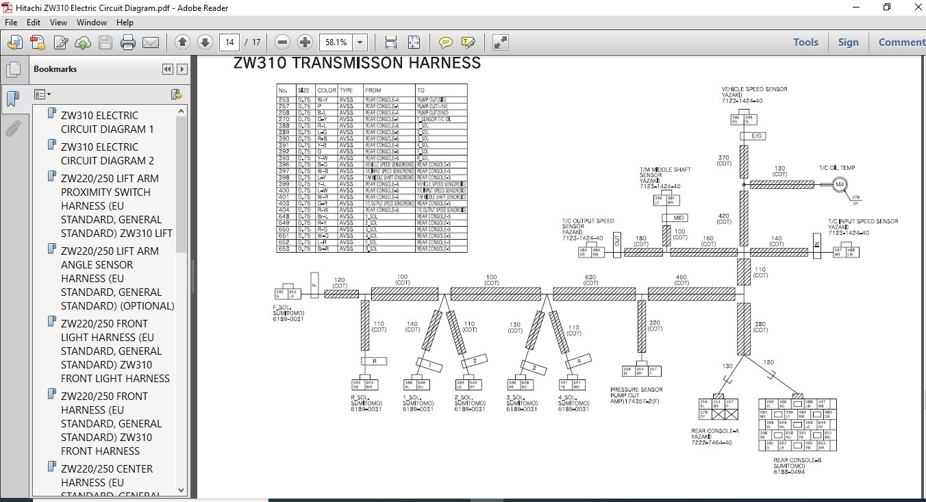

Table of Contents:
Hitachi ZW310 Electric Circuit Diagram
ZW310 ELECTRIC CIRCUIT DIAGRAM 1........................................................................................................................................................ 1
ZW310 ELECTRIC CIRCUIT DIAGRAM 2 ....................................................................................................................................................... 2
ZW220/250 LIFT ARM PROXIMITY SWITCH HARNESS (EU STANDARD, GENERAL STANDARD) ZW310 LIFT ARM PROXIMITY SWITCH HARNESS .................................................................... 3
ZW220/250 LIFT ARM ANGLE SENSOR HARNESS (EU STANDARD, GENERAL STANDARD) (OPTIONAL) ZW310 LIFT ARM ANGLE SENSOR HARNESS (OPTIONAL) ...................................................... 4
ZW220/250 FRONT LIGHT HARNESS (EU STANDARD, GENERAL STANDARD) ZW310 FRONT LIGHT HARNESS ................................................................................................ 5
ZW220/250 FRONT HARNESS (EU STANDARD, GENERAL STANDARD) ZW310 FRONT HARNESS ............................................................................................................ 6
ZW220/250 CENTER HARNESS (EU STANDARD, GENERAL STANDARD) ZW310 CENTER HARNESS .......................................................................................................... 7
ZW220/250 FRONT CONSOLE HARNESS 1 (EU STANDARD, GENERAL STANDARD) ZW310 FRONT CONSOLE HARNESS 1 ........................................................................................ 8
ZW220/250 FRONT CONSOLE HARNESS 2 (EU STANDARD, GENERAL STANDARD) ZW310 FRONT CONSOLE HARNESS 2 ........................................................................................ 9
ZW220/250 SIDE CONSOLE HARNESS 1 (EU STANDARD, GENERAL STANDARD) ZW310 SIDE CONSOLE HARNESS 1 ..........................................................................................10
ZW220/250 SIDE CONSOLE HARNESS 2 (EU STANDARD, GENERAL STANDARD) (FOR STANDARD TWO LEVER PILOT VALVE) ZW310 SIDE CONSOLE HARNESS 2 (FOR STANDARD TWO LEVER PILOT VALVE) ................11
ZW220/250 SIDE CONSOLE HARNESS 3 (EU STANDARD, GENERAL STANDARD) (FOR OPTIONAL JOY STICK LEVER PILOT VALVE) ZW310 SIDE CONSOLE HARNESS 3 (FOR OPTIONAL JOY STICK LEVER PILOT VALVE) ....12
ZW310 REAR CONSOLE HARNESS .............................................................................................................................................................13
ZW220/250 TRANSMISSION HARNESS (GENERAL STANDARD) ZW310 TRANSMISSION HARNESS ...........................................................................................................14
ZW310 REAR FRAME HARNESS ...............................................................................................................................................................15
ZW310 HYDRAULIC CIRCUIT DIAGRAM (EU STANDARD) ..........................................................................................................................................16
ZW310 HYDRAULIC CIRCUIT DIAGRAM (GENERAL STANDARD) .....................................................................................................................................17
Description:
Hitachi ZW310 Electric Circuit Diagram
FOREWORD:
- According to Hitachi’s continuous effort to improve the product quality. descriptions in the Parts Catalog may be slightly different from your machine. If any questionable points are found, feel free to contact your nearest Hitachi dealer.
- For, the engine parts, please refer to the parts catalog of diesel engine issued separately.
1.HOW TO ORDER PARTS
When ordering parts. please specify the following items.
- Model type
- Product Identification Number
- Part No.
- Part Name
- my
- Purchaser’s Name and Address
2.HOW TO USE THIS PARTS CATALOG
PART NAME: When the part is used as an inner part of an assembly part, the mark ‘3‘ is shown in front of the part name.
Q’TY: Indicates the number of the part used per machine. The quantity of an inner part is the number of the inner part necessary to organize one assembly part.
Please Note:
- This is the SAME exact manual used by your dealers to fix your vehicle.
- The same can be yours in the next 2-3 mins as you will be directed to the download page immediately after paying for the manual.
- Any queries / doubts regarding your purchase, please feel free to contact [email protected]


